ORFS one-piece fitting sealing verification requires a group of matching observations, measurements, gauge checks, and hose-side records; outside diameter or swivel appearance cannot confirm the order alone. The process must distinguish connection size from measured thread diameter, verify Thread Pitch or TPI and flat-face and groove condition, identify Male or Female Connection, and rule out flare, tapered-thread, and other candidates. It must then add Hose Dash, Fitting Series, and Straight, 45-Degree, or 90-Degree Configuration.
ORFS Identity Requires More Than a Swivel Nut
An ORFS connection uses a designed flat-face and O-ring interface for sealing while straight threads and the nut provide mechanical engagement. The swivel nut alone does not prove ORFS because other connection families also use swivel components.
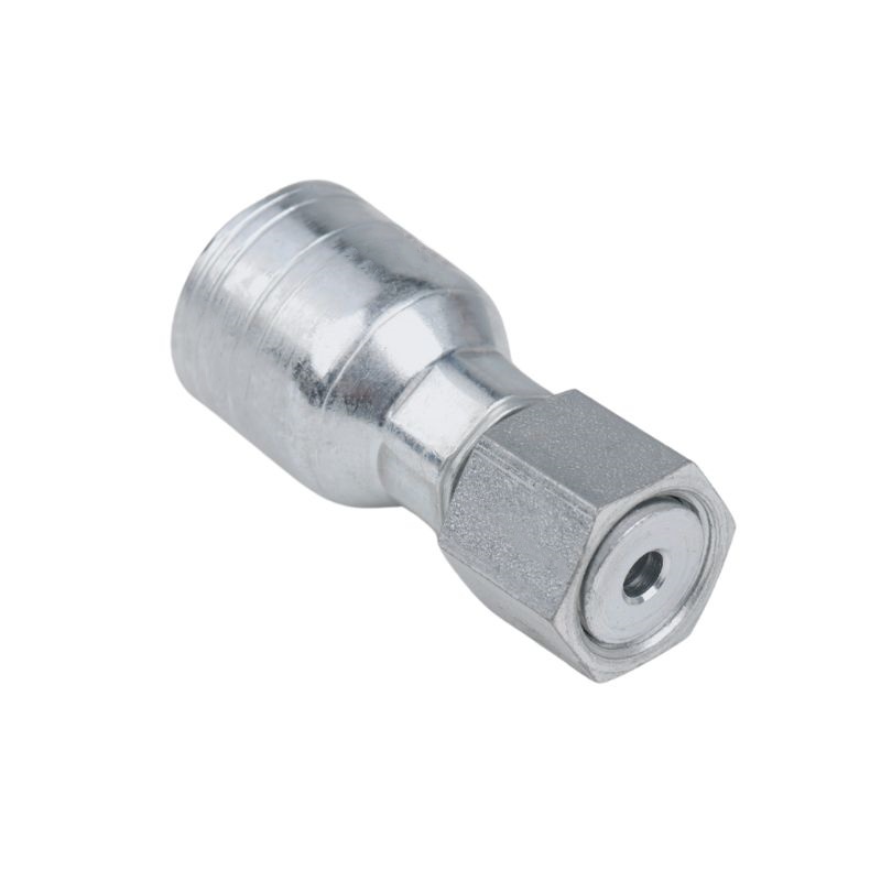
Confirm the flat face, O-ring groove, and straight thread
On the male ORFS side, identify the flat sealing face and the designed groove that retains the specified O-ring. On the female swivel side, inspect the mating flat face that compresses the seal. Confirm thread form, diameter, pitch, connection gender, and size with suitable tools and current controlled references; thread engagement is supporting evidence, not proof of the seal design.
The groove, face, and O-ring work as a system. The thread does not replace the O-ring, and thread compound cannot repair a damaged face or an incorrect seal. A fitting that resembles ORFS but lacks the correct groove or mating geometry must remain an unconfirmed candidate.
Rule out other sealing methods deliberately
Flare connections seal through angled metal surfaces, and tapered-thread connections develop their intended joint through different thread geometry and procedures. ORFS instead depends on controlled compression of the correct O-ring between aligned flat faces. These methods are not interchangeable, even if thread dimensions or swivel appearance seem similar.
Photographs can narrow candidates, but final confirmation may require thread measurements, groove and face inspection, a verified drawing, fitting markings, hose-side information, and application records. Keep visual screening separate from final approval.
The Flat Face and O-Ring Must Be Evaluated Together
The flat face supports alignment and compression, while the specified O-ring supplies the resilient sealing element. Either part can defeat the intended ORFS sealing method when damaged, contaminated, incorrectly selected, or assembled out of alignment.
Inspect surfaces and groove condition
Clean the connection by an approved method and inspect for dents, radial scratches, corrosion, embedded debris, deformation, and raised damage that could cross the sealing path. Examine the groove for damage, contamination, or geometry inconsistent with controlled product data. Do not invent groove tolerances or attempt to reshape the groove in the field.
Surface discoloration alone does not establish leakage risk, and a smooth-looking photograph cannot prove flatness or groove conformity. Record the condition, lighting, magnification if used, and the applicable drawing or acceptance reference. Replace or escalate suspect pressure-containing parts according to the approved procedure.
Verify the O-ring as an application component
Confirm the O-ring size, material, condition, source or specification, and compatibility with the fluid, temperature, environment, and equipment requirements. Do not install an O-ring merely because it fits into the groove. Stretching, twisting, cuts, flattening, swelling, hardening, contamination, or an unknown material are reasons to stop and resolve the seal requirement.
Lubrication, installation tools, and replacement rules must follow current component and equipment instructions. Never use thread tape or compound to compensate for an incorrect O-ring or damaged ORFS face.
Surface, Groove, and Seal Checks Answer Different Questions
Calipers, pitch gauges, thread gauges, and inspection records are complementary. No single tool proves the complete identity, and every tool must be suitable, serviceable, and used according to its instructions.
Match the tool to the question
| Sealing method | Primary sealing interface | Thread role | Key confirmation |
| ORFS | Specified O-ring compressed between designed flat faces | Draws faces together and retains engagement | Face, groove, O-ring, alignment, and straight-thread identity |
| Flare connection | Matching angled metal sealing surfaces | Draws flare seats into contact | Correct flare standard, seat angle, surface condition, and gender |
| Tapered-thread connection | Designed tapered-thread interface under its specified procedure | Participates in engagement and joint formation | Correct thread form, pitch, taper, size, and permitted sealing procedure |
Use a pitch gauge only after cleaning the thread without altering it. The gauge leaf should seat consistently across usable threads; do not select the leaf that contacts at one point while gaps remain elsewhere. Record TPI for inch-thread candidates or the applicable pitch expression for other candidates rather than using the words “coarse” or “fine.”
Check groove and face geometry through a controlled method
flat-face and groove condition should be evaluated using a suitable gauge or a documented measurement method and verified reference. A visual narrowing, changing caliper reading, or partial engagement is not by itself proof of the required groove and face geometry. The appropriate method depends on whether the connection is male or female and what inspection equipment is available.
Never force an unknown fitting into a port as a thread gauge. Partial engagement can occur between mismatched connection systems, and added torque can cross-thread or permanently damage both components. If a correct gauge, clean usable thread, or reliable reference is unavailable, record the limitation and keep the result preliminary.
Hose Side, Series, and Orientation Complete the Part
Correctly identifying the pipe thread still does not identify the complete one-piece fitting. The order must include connection gender, hose-side compatibility, and physical configuration.

Record Male or Female Connection precisely
State Male or Female Connection from the actual port end being ordered, not from the mating component or a casual description such as “male hose.” Record relevant swivel behavior, hex or wrench features, and any sealing or orientation detail that affects installation. A female port on the machine does not mean the removed hose fitting should be described as female.
Confirm thread condition at the same time. Flattened crests, torn threads, corrosion, contamination, cross-threading, or previous over-tightening may distort measurements and make the sample unsuitable for final gauging. A damaged sample can still supply clues, but the record must show why further reference or a sound mating component is needed.
Separate Hose Dash from the port designation
Hose Dash is the nominal hose-side size and must not be copied from connection size or a port-dash description. Confirm the hose manufacturer, Hose Series, Hose Construction, reinforcement, and dash, then identify the approved Fitting Series, stem, ferrule, Crimping Machine, Die Set, and current crimp data. Equal dash values do not prove hose and fitting compatibility.
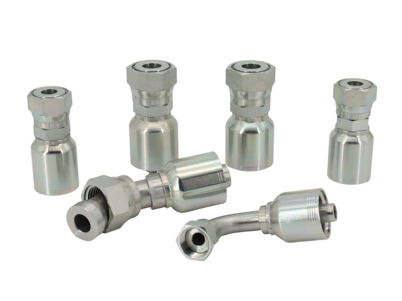
Also specify Straight, 45-Degree, or 90-Degree Configuration. For elbows, record the hose-tail direction, orientation, clearance, and swivel or fixed behavior where relevant. The right ORFS thread on the wrong angle can make installation impossible or force a hose into excessive bend, twist, abrasion, or movement interference.
Follow a Step-by-Step ORFS Verification Process
A controlled sequence preserves evidence and prevents early assumptions from shaping later measurements. Complete the thread decision before translating it into a purchasing description, but retain the hose side and geometry throughout the inspection.
Stage 1: make safe, clean, and document
Before removal, stop the equipment, isolate the hydraulic circuit, release pressure and stored energy, secure raised or suspended loads, and follow applicable lockout and equipment-manufacturer instructions. Never touch a suspected injection leak or loosen a fitting to “see whether pressure remains.” Mark hose orientation and capture installation clearance before moving the assembly if those details could be lost.
After safe removal, protect the port and clean the sample using a method that does not reshape the threads. Photograph the entire fitting, connection end, hose side, markings, and damage. Record the equipment position, mating-port information, old number as an unverified lead, Male or Female Connection, and Straight, 45-Degree, or 90-Degree Configuration.
At this stage, collect:
- equipment and hydraulic position, mating component, and safe-removal record;
- complete-fitting, thread, hose-tail, marking, and orientation photographs;
- connection gender, visible sealing behavior, thread condition, and configuration;
- hose layline, manufacturer, series, construction, Hose Dash, and current fitting series if known;
- measuring tools, reference documents, inspector, and traceability identifier.
Stage 2: measure independent thread features
Measure the accessible diameter with a suitable caliper and record the exact location and condition. Check Thread Pitch or TPI with an appropriate pitch gauge, then evaluate flat-face and groove condition with the correct gauge or documented method. Do not adjust a measurement simply because it conflicts with the expected ORFS candidate; the conflict is evidence that the assumption, sample, or method needs review.
Compare diameter, pitch or TPI, groove and face geometry, gender, and thread form with current authoritative references. Deliberately compare plausible alternatives, including flare and tapered-thread connections, rather than stopping when one ORFS feature appears to match. If the sample is worn or damaged, use a verified drawing, sound port data, suitable gauge results, or other controlled evidence before final acceptance.
Stage 3: confirm the whole fitting and decision status.
Once the thread candidate is supported, confirm connection size from the verified reference, then add Hose Dash, Fitting Series, ferrule, configuration, material, finish, and critical dimensions. Review application pressure, temperature, fluid, environment, and routing; the lowest-rated component limits the complete assembly. Confirm the current hose and crimp procedure rather than assuming one-piece construction guarantees assembly suitability.
Mark the result as accepted only when every required field has evidence. If the thread is likely ORFS but groove and face geometry gauging is unavailable, or the hose series cannot be identified, state the unresolved point and keep the record preliminary. A controlled incomplete result is safer than a complete-looking order built on guesses.
ORFS Threads Engage; the Face and O-Ring Seal
Straight threads draw the two faces together and maintain mechanical engagement; they are not the primary sealing surface. Reliable performance depends on correct alignment, an undamaged interface, the specified O-ring, and the approved assembly procedure.
Assemble without hiding misalignment
Align the fitting before tightening so the faces meet evenly and the hose is not forced into twist or side load. Support elbows and routed assemblies as required, preserve bend radius and clearance, and use the current torque or assembly method from the responsible manufacturer. This article gives no universal torque because size, material, design, lubrication, and instructions vary.
If resistance appears abnormal, stop rather than using torque to pull misaligned components together. Cross-threading, a trapped seal, damaged faces, or incompatible parts may otherwise be concealed until leakage or service damage occurs.
Diagnose leakage safely
Stop equipment, isolate the circuit, release hydraulic pressure and stored energy, secure suspended loads, and follow lockout and equipment instructions before inspection. Never touch a suspected high-pressure leak or tighten the joint while it is pressurized. Use approved inspection methods.
After safe disassembly, preserve the O-ring and component condition for evidence. Check seal identity, groove and face damage, contamination, alignment, thread condition, hose routing, and application data. Replacing only the O-ring without finding the cause can allow the same problem to recur.
Prevent ORFS Errors With a Final Confirmation Checklist
Most bad orders preserve only a thread label and omit the evidence behind it. The purchasing description should allow another qualified person to verify the candidate without handling the original sample.
Review common failure points
Common errors include treating measured thread diameter as connection size, calling every straight thread ORFS, estimating TPI from a photo, and copying an old number without checking revision or application. Other mistakes are describing the mating port’s gender instead of the fitting, equating Hose Dash with port size, and omitting elbow orientation. Thread compound is then misused to compensate for a mismatch that should have been stopped at inspection.
Before order approval, confirm:
- accepted thread standard and decision status, connection size, measured thread diameter with location, Thread Pitch or TPI, and flat-face and groove condition evidence;
- Male or Female Connection, thread condition, sealing method, mating-port identity, and applicable reference;
- Hose Dash, Hose Manufacturer, Hose Series, Hose Construction, Fitting Series, ferrule, and current crimp data;
- Straight, 45-Degree, or 90-Degree Configuration, orientation, swivel behavior, clearance, and critical dimensions;
- material, finish, pressure, fluid, temperature, application, photographs, gauge record, and approval traceability.
Conclusion
Reliable identification comes from several independent features agreeing, not from a familiar appearance or one caliper reading. Preserve the installation evidence, distinguish connection size from measured thread diameter, and verify Thread Pitch or TPI, flat-face and groove condition, gender, thread condition, and sealing behavior with suitable tools and current references. Deliberately rule out flare, tapered-thread, and other candidates before final acceptance. Then complete the order with Hose Dash, Fitting Series, ferrule, Straight, 45-Degree, or 90-Degree Configuration, material, application, and controlled crimp data. Never force engagement or use thread compound to conceal mismatch. Keep the inspection record with the approved order for future verification. A documented ORFS one-piece fitting sealing verification process prevents bad orders while protecting the port and the finished hose assembly.
Frequently Asked Questions
Does a swivel nut prove that a fitting is ORFS?
No, a swivel nut alone does not prove ORFS identity. Confirm the flat mating face, male O-ring groove, straight-thread features, size, and controlled reference before approval.
Can any O-ring that fits the groove be used?
No, physical fit does not prove the correct size, material, or application compatibility. Verify the specified seal against fluid, temperature, equipment, and component requirements.
Can thread compound stop an ORFS face leak?
No, thread compound cannot repair a damaged face, wrong O-ring, or misaligned connection. Isolate and depressurize the system, then inspect the actual sealing interface safely.
Should a flattened O-ring simply be replaced?
Replacement may be necessary, but the cause must also be investigated. Check groove condition, seal identity, assembly procedure, alignment, fluid exposure, and service history before reassembly.
Is ORFS always better than a flare connection?
No, ORFS is not universally superior to every connection. Its suitability depends on equipment design, application conditions, hose and fitting compatibility, installation controls, and correct seal maintenance.