The internal bore affects hydraulic flow by setting the passage area and shaping local transitions that influence velocity and pressure loss. A one-piece fitting internal bore can be mechanically compatible with a thread and hose yet still be hydraulically restrictive when its effective area, elbow path, or internal step is smaller or sharper than the surrounding circuit. The result may include added pressure drop, heat, slower actuator response, or more demanding inlet conditions, depending on flow, fluid, temperature, and system design. Thread size alone cannot answer the question. Selection requires verified internal geometry and operating data for the hose, port, fitting, adapters, and complete flow path.
Thread Size Does Not Define Flow Area
Connection size identifies an interface, not the smallest usable passage through the fitting. The thread, seat, wall thickness, hose tail, swivel, and manufacturing transitions can leave an internal area that differs from the nominal port or hose size.
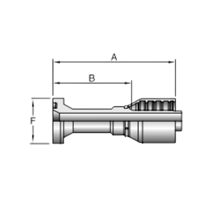
Find the controlling passage
Review the complete internal path from port entry to hose tail and identify its smallest effective section. A drawing should distinguish thread dimensions from flow dimensions and show whether internal features, seats, steps, or inserts reduce the passage. A single outside measurement or catalog dash number cannot reveal that boundary.
Compare exact configurations
Straight and elbow fittings within one family may not share identical internal geometry, and sizes do not scale in one universal ratio. A replacement should therefore be compared by exact part revision, connection, hose side, and flow drawing. Visual similarity or successful thread engagement proves neither passage area nor hydraulic equivalence.
Manufacturing details also need an appropriate control boundary. Drilling, forming, intersections, and deburring can affect the realized passage, but an article cannot define acceptable variation without a drawing or specification. If bore geometry is a critical characteristic, state where and how it is measured, which revision controls it, and how receiving evidence relates to the delivered lot. A nominal catalog description without a measurement reference is not enough for a pass/fail decision.
Useful data includes:
- Verified internal passage dimensions and drawing references.
- Exact connection, sealing form, hose dash, and fitting series.
- Hose ID, port passage, adapters, valves, and adjacent restrictions.
- Required flow range, fluid properties, and temperature condition.
- Acceptable circuit pressure loss, heat, noise, and response criteria.
Bore and Transitions Change Velocity
For a given flow, velocity rises where effective area becomes smaller. Exact evaluation requires verified dimensions and fluid data, but the qualitative rule helps identify where a fitting can become a local restriction.
Area changes create local acceleration
Fluid accelerates into a reduced section and slows as the passage expands. Abrupt contractions or expansions can create greater local loss than gradual transitions. The effect depends on geometry and operating condition, so it should not be estimated from outside diameter or thread size.
Smoothness is not the only criterion
A visually smooth passage can still be too small for the required flow, while a larger passage can weaken an unsuitable design or conflict with sealing geometry. The largest bore is not automatically best. The selected fitting must meet verified mechanical, pressure, connection, and manufacturing requirements as well as the system’s hydraulic targets.
Elbows and Local Geometry Add Loss
Elbows redirect flow and can add local loss through curvature, turns, area changes, and internal features. Two 90-degree fittings with similar external envelopes may have different effective paths, so angle alone does not establish performance.
Bend shape matters
Centerline radius, cross-section, surface condition, entry transition, and downstream recovery influence flow behavior. A compact elbow may solve clearance but create a more restrictive path than a longer arrangement. This tradeoff should be reviewed with verified product data rather than a universal elbow penalty.
Orientation affects system layout
Adding adapters to obtain the needed direction can create more interfaces and restrictions than a suitable angled fitting, but replacing several parts with one elbow is not automatically better. Check installation envelope, hose routing, bend radius, service access, sealing interfaces, and total flow path together.
| Flow-path feature | Possible hydraulic effect | Information required |
| Smallest bore section | Higher local velocity and pressure loss | Verified effective dimensions |
| Abrupt contraction | Acceleration and local loss | Transition geometry and flow data |
| Abrupt expansion | Separation and recovery loss | Geometry and downstream condition |
| Elbow or turn | Directional local loss | Bend shape, passage, and orientation |
| Multiple adapters | Accumulated restrictions and interfaces | Complete installed path |
| Mismatch with hose or port | One component becomes the bottleneck | Hose ID, port bore, and fitting passage |
Restriction Can Contribute to Heat and Performance Problems
Pressure energy lost across a restriction can become heat, but a fitting should not be blamed without system evidence. Pumps, valves, undersized hoses, filters, fluid condition, and control settings may create similar symptoms.
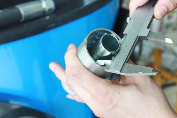
Look for system-level consequences
Excessive local loss may reduce available pressure downstream, slow motion, change actuator response, or raise required pump output. In suction or inlet paths, restrictive conditions may contribute to poor filling or cavitation risk. The actual result depends on circuit location, flow, viscosity, temperature, and duty cycle.
Diagnose rather than assume
Compare temperatures and pressures using approved measurement methods at meaningful operating states. Review whether the symptom changes with flow, fluid temperature, or actuator demand. Never touch a suspected hot or leaking component under pressure, and do not replace a fitting with a visually larger passage without confirming all mechanical and safety requirements.
Diagnosis should begin with a safe baseline of the circuit configuration and operating command. A partly closed valve, loaded filter, damaged hose liner, incorrect adapter, or control setting can create a restriction that appears to belong to the fitting. Record measurement locations and instrument condition so readings taken at different points or duties are not compared as equivalents. The purpose is to locate the loss, not to prove a preferred component is responsible.
Hose ID, Port Size, and Bore Work Together
The flow path is only as effective as its combined restrictions. A large hose cannot remove a small port restriction, and a large fitting bore cannot correct an undersized hose or valve passage.
Avoid dash-size shortcuts
Hose dash, port dash, and fitting connection size describe related but different identities. The hose’s actual ID varies by construction and series, while port and fitting passages depend on design. Record each separately so a nominal match does not conceal a smaller effective section.
Review transitions between components
Adapters, reducers, swivel ends, and hose tails can introduce steps even when each component is individually acceptable. Map the installed sequence and check the smallest area, transition quality, number of turns, and cumulative loss. Also verify pressure rating, sealing, torque or assembly procedure, and clearance for every interface.
Routing can change the practical result after a component comparison. A theoretically lower-loss fitting may require a tighter hose bend, extra length, poorer support, or an adapter to fit the available envelope. Those changes may remove the expected benefit or create a different reliability problem. Evaluate the installed option, including motion and service access, rather than ranking isolated fittings on bore size alone.
Review Bore Data Before Selection
A repeatable review starts with operating requirements and ends with a documented comparison of complete configurations. Missing geometry should remain an engineering unknown rather than being replaced with an unsupported flow claim.
Define the required condition
Record normal, minimum, peak, and transient flow conditions; fluid identity and viscosity at relevant temperatures; acceptable pressure loss; circuit location; duty cycle; and performance consequences. Suction, return, pressure, pilot, and drain lines may have different design priorities, so a result from one location should not be transferred automatically.
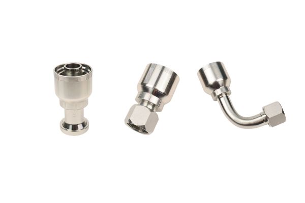
Obtain configuration-specific evidence
Request a drawing or verified flow-passage data for the exact part and revision. Where quantitative evaluation is required, use an approved engineering method with actual geometry, fluid properties, and operating data. A generic family curve, another size, or an unexplained coefficient should not be treated as proof.
If comparative test data is used, check the test medium, temperature, flow range, pressure measurement locations, setup, specimen identity, and reported uncertainty or limitations. Results from a different port arrangement or hose connection may include losses that are absent from the proposed installation, or omit losses that are present. A plotted curve is useful only when its axes, configuration, and scope are clear enough to support the intended decision.
The review should also consider future operating changes. Higher production demand, a different actuator speed, colder fluid, a revised valve, or added filtration can change the flow condition through the same fitting. Preserve the approved duty and calculation inputs with the component record. When the system changes, revisit the flow path rather than assuming the original conclusion contains unlimited margin.
Review steps include:
- Confirm the exact fitting, hose, port, adapter, and valve path.
- Identify the smallest passage and every major turn or transition.
- Use actual fluid, temperature, viscosity, and flow conditions.
- Evaluate pressure loss and heat against system criteria.
- Verify pressure, material, seal, hose, crimp, and installation suitability separately.
Common Bore-Selection Mistakes
Common mistakes include choosing by thread size, assuming larger is always better, comparing outside dimensions, and ignoring cumulative local losses.
Do not confuse mechanical fit with hydraulic fit
A connection can thread correctly and seal while restricting the circuit. Conversely, a generous passage does not approve thread, seat, material, wall strength, or pressure capability. Both hydraulic and mechanical checks must pass for the exact application.
Avoid unsupported calculations
Do not invent bore diameters, flow coefficients, or universal flow limits. Simplified equations can be useful only when their assumptions and inputs match the geometry and flow regime. If verified data is unavailable, state what must be measured or supplied and keep the performance conclusion open.
Neutral Flow-Review Checklist
The final record should make the flow decision reproducible and preserve the separate assembly approvals.
Information to prepare
- Exact fitting revision, internal geometry, connection, seal, angle, and hose side.
- Hose ID and construction, port bore, adapters, valves, and complete installed sequence.
- Fluid, viscosity, temperature, flow range, duty cycle, and circuit function.
- Acceptable pressure loss, heat, noise, and response criteria.
- Verified pressure, material, hose, crimp, routing, and safety data.
- Unknown dimensions, assumptions, calculation method, and approval responsibility.
If the passage data is missing, a sample can be measured under an approved method, but the result should not be generalized to other sizes or revisions.
Keep the approved drawing, measurement record, calculation inputs, and installed configuration together so later purchasing or maintenance changes do not erase the original flow decision.
Conclusion
Internal bore influences flow through its smallest effective area, transitions, turns, and relationship with the surrounding circuit. Thread size, outside appearance, and hose dash cannot define that passage. Map the complete route through ports, adapters, fittings, elbows, and hose; then use verified geometry, flow, fluid, viscosity, temperature, and duty information to evaluate velocity, local loss, heat, and response. The largest bore is not automatically the correct choice because pressure strength, sealing geometry, installation space, and hose compatibility still matter. Before approving a one-piece fitting internal bore for hydraulic flow, prepare exact drawings and system criteria, document unknowns, and complete separate pressure, material, seal, hose, crimp, and safety checks for the selected configuration, and preserve that boundary throughout the equipment lifecycle.
FAQ
Does a larger thread always provide more flow?
No, thread size does not identify the smallest internal passage. Seats, walls, hose tails, swivels, ports, and adapters can control effective flow area.
Are elbow fittings always too restrictive?
No, their effect depends on bend geometry, passage area, flow, fluid, and system criteria. Use verified data for the exact elbow rather than a universal rule.
Can pressure drop be calculated from bore diameter alone?
No, exact evaluation also needs passage length, transitions, turns, surface and flow behavior, fluid properties, temperature, and operating flow.
Can a fitting restriction cause hydraulic heat?
It can contribute because pressure loss can become heat, but other circuit components may be responsible. Diagnose the complete system under approved procedures.
Does a mechanically compatible replacement have the same flow capacity?
Not necessarily. Internal geometry, elbow shape, transitions, hose tail, and passage area may differ even when threads and external dimensions appear to match.