As a hydraulic system designer, you know that selecting the wrong fitting size can choke your system. It leads to excess heat, wasted energy, and poor performance.
To select the right hydraulic fitting, you must calculate the required internal area based on the system’s flow rate (Q) and a target fluid velocity (V). This balance ensures optimal efficiency by minimizing pressure drop and heat generation. The core formula is Area = Flow Rate / Velocity.
Why Does Proper Sizing Matter So Much?
You’ve designed a powerful hydraulic circuit, but if the fittings are too small, performance will suffer dramatically. The impact goes far beyond a simple flow restriction.
Proper fitting size is critical because it directly controls fluid velocity. An undersized fitting increases velocity, causing excessive pressure drop, heat generation, and turbulence. This wastes energy, can damage components, and reduces the available force at your actuator, compromising the entire system’s performance.

Think of it like a highway. A three-lane highway allows traffic to flow smoothly. If it suddenly narrows to one lane, you get a traffic jam (pressure drop), frustrated drivers (heat), and wasted time and fuel (energy loss). Your hydraulic system behaves the same way. Every fitting is a potential bottleneck, and our job as designers is to ensure the “road” is wide enough for the “traffic” to move efficiently.
The High Cost of Pressure Drop
Pressure drop is the loss of pressure as fluid moves through a component. While some loss is unavoidable, excessive drop in a fitting is a sign of poor sizing. Every PSI of pressure lost is energy that is completely wasted. It is converted directly into heat and does not perform any useful work. This lost pressure must be made up by the pump, forcing it to work harder and consume more power to achieve the required force at the cylinder or motor.
Heat: The Silent Killer of Hydraulic Systems
That wasted energy from pressure drop becomes heat. Excess heat is a primary enemy of hydraulic systems.
- It degrades hydraulic oil, reducing its lifespan and lubricating properties.
- It causes seals and hoses to become hard and brittle, leading to premature leaks and failures.
- It can cause the viscosity of the fluid to drop, leading to internal leakage in pumps and valves, further reducing efficiency.
Properly sized fittings help keep fluid velocity in check, which is one of the most effective ways to minimize heat generation.
Damage from High Velocity and Turbulence
When fluid velocity is too high (especially over 20-25 ft/sec), the flow can become turbulent. Turbulent flow is chaotic and erosive. It can physically wear away the inside of hoses and fittings over time. More importantly, it can cause dissolved air in the fluid to escape, a phenomenon similar to cavitation, which can damage pumps and other sensitive components. Sizing fittings correctly keeps the flow smooth and laminar, protecting the system’s long-term health.
What’s the Core Formula for Sizing?
To move from theory to practice, you need a formula. The relationship between flow, velocity, and area is the foundation of all hydraulic sizing calculations.
The fundamental formula is Q = V x A, where Q is the flow rate, V is the fluid velocity, and A is the internal area of the fitting or hose. To find the size you need, you rearrange this to A = Q / V. This simple equation is the key to sizing every fluid conductor in your system.
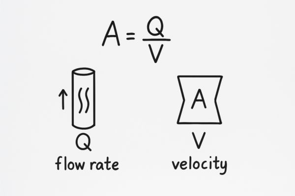
This calculation forms the basis of all our work. You start with two pieces of information: the required flow rate of your system (determined by the speed you need from your actuator) and an ideal target velocity (based on industry best practices). By dividing the flow rate by the velocity, you calculate the exact internal cross-sectional area your conductor needs to have. Your final task is to choose a fitting with an internal area that is equal to or slightly larger than this calculated value.
The Three Key Variables
- Q (Flow Rate): This is the volume of fluid passing a point per unit of time. It is determined by your system’s requirements (e.g., how fast a cylinder must extend). It is typically measured in Gallons Per Minute (GPM) or Liters Per Minute (LPM).
- V (Fluid Velocity): This is the speed at which the fluid is moving. It is your primary design choice. You select a target velocity to balance efficiency and component size. It is measured in Feet Per Second (ft/s) or Meters Per Second (m/s).
- A (Area): This is the cross-sectional area of the inside of the fitting or hose. This is the value you are trying to find. It is measured in square inches (in²) or square millimeters (mm²).
Getting the Units Right is Crucial
The biggest source of error in this calculation is mismatched units. You cannot simply divide GPM by ft/s. You must convert your units so they are compatible. Here’s a practical conversion factor:
To find Area (in²) from GPM and ft/s:
Area (in²) = (GPM * 0.3208) / Velocity (ft/s)
This single formula is your most powerful tool. The constant 0.3208 converts gallons per minute into cubic inches per second, making the units compatible.
A Quick Example
Let’s say your system requires a flow of 10 GPM and you are designing a pressure line where a velocity of 15 ft/s is ideal.
- Area (in²) = (10 GPM * 0.3208) / 15 ft/s
- Area (in²) = 3.208 / 15
- Area (in²) = 0.214 in²
Now you know you need a fitting and hose with an internal cross-sectional area of at least 0.214 square inches.
How Do You Choose the Right Fluid Velocity?
The calculation is simple, but it depends entirely on choosing the correct target velocity (V). This choice is not random; it’s a critical design decision based on the type of line you are sizing.
You choose a target fluid velocity based on established industry recommendations for different line types. Suction lines require very low velocity to prevent pump cavitation, while pressure and return lines can handle higher velocities to allow for smaller, more cost-effective components.
Choosing the right velocity is a balancing act. A lower velocity means less pressure drop and lower heat generation, which is great for efficiency. However, it also requires a larger, more expensive hose and fittings. A higher velocity allows for smaller, cheaper components, but at the cost of higher energy loss and potential for turbulence. Following these guidelines is the best way to find the optimal balance for your system.
Recommended Velocity Ranges
As professional designers, we adhere to these standard velocity guidelines to ensure reliable and efficient system operation. Sticking within these ranges is a proven best practice.
| Line Type | Recommended Velocity (ft/s) | Recommended Velocity (m/s) | Justification |
| Suction Lines | 2 – 4 ft/s | 0.6 – 1.2 m/s | Critical. Keeps velocity low to prevent starving the pump and causing cavitation. |
| Pressure Lines | 7 – 18 ft/s | 2.1 – 5.5 m/s | A balance between efficiency and component size. Higher pressure systems often use the upper end of this range. |
| Return Lines | 5 – 10 ft/s | 1.5 – 3.0 m/s | Velocity is kept moderate to avoid creating back pressure that could affect system operation. |
Consequences of Exceeding Velocity Limits
- In Suction Lines: Exceeding 4 ft/s can create a vacuum at the pump inlet that is too high. This can cause the oil to vaporize, creating bubbles that implode under pressure inside the pump. This phenomenon, called cavitation, is extremely loud and destructive, quickly destroying the pump.
- In Pressure Lines: Exceeding 18-20 ft/s leads to significant pressure drop, wasting energy and generating excessive heat. The flow can also become turbulent, leading to noise, vibration, and erosion of system components.
When to Adjust Your Target Velocity
While these are excellent guidelines, sometimes you need to adjust them. For systems with very long hose runs, you might choose a velocity at the lower end of the pressure line range (e.g., 10 ft/s) to minimize the cumulative pressure drop. Conversely, in a short, intermittent-use line on a mobile machine, you might push the velocity higher to save space and weight. This is a judgment call based on experience.
How Do You Convert Area to a Fitting Size?
You’ve calculated that you need a fitting with an area of 0.214 in². Now what? You need to translate this number into a real-world part you can order.
You convert the required area into a fitting size by first calculating the required internal diameter (ID). Then, you match this ID to a standard industry “dash size.” Dash sizes correspond to specific hose and fitting IDs, allowing you to easily select the right component from a catalog.

The world of hydraulic fittings operates on the “dash size” system. This is simply a shorthand way of specifying the size of a hose or fitting. Understanding this system is the final step in connecting your theoretical calculation to a physical part. Once you find the dash size, you can confidently select any fitting—JIC, ORFS, NPT—of that size, knowing it’s right for your flow rate.
Finding the Required Diameter
The formula for the area of a circle is A = π * r². To find the diameter you need, you can rearrange this.
- Area = π * (Diameter / 2)²
- Area = (π * Diameter²) / 4
- Diameter = √((4 * Area) / π)
Let’s use our previous example where we calculated a required area of 0.214 in²:
- Diameter = √((4 * 0.214) / 3.14159)
- Diameter = √(0.856 / 3.14159)
- Diameter = √0.2725
- Diameter = 0.522 inches
So, you need a hose and fitting with an internal diameter of at least 0.522 inches.
Matching Diameter to Dash Size
The dash size number represents the internal diameter of the hose in sixteenths of an inch. A “-8″ hose, for example, has an ID of 8/16″, or 1/2″ (0.500”).
Looking at our calculated ID of 0.522″, we need to choose the next size up.
| Dash Size | Nominal ID (inches) | ID (decimal) | Internal Area (in²) |
| -6 | 3/8″ | 0.375 | 0.110 |
| -8 | 1/2″ | 0.500 | 0.196 |
| -10 | 5/8″ | 0.625 | 0.307 |
| -12 | 3/4″ | 0.750 | 0.442 |
Our required ID (0.522″) is larger than a -8 (0.500″). Therefore, we must select the next size up: **-10**. A -10 fitting and hose is the correct choice for this application. Choosing the smaller -8 size would have resulted in excessively high fluid velocity.
What About Pressure Drop in Fittings?
Sizing for velocity gets you 90% of the way there. But for high-precision systems, you also need to estimate the pressure drop from the fittings themselves, especially elbows and tees.
Every fitting introduces a small amount of pressure drop due to friction and turbulence. While straight fittings have a minimal effect, fittings that change the flow direction, like elbows and tees, create significantly more turbulence and thus a higher pressure drop. This must be considered in sensitive systems.
For many systems, the pressure loss from a few fittings is negligible. However, in a system with many bends, or where every PSI of pressure counts, you need to account for it. This is done by treating each fitting as an “equivalent length” of straight hose. An elbow fitting might create the same pressure drop as several feet of hose, and this must be added to your overall system pressure drop calculation.
The Concept of Equivalent Length
The easiest way to account for fitting losses is to use the concept of equivalent length. Manufacturer data provides tables that list how many feet of straight hose have the same pressure drop as a single fitting.
- A straight male connector might be equivalent to only 0.5 feet of hose.
- A 45-degree elbow might be equivalent to 2-3 feet of hose.
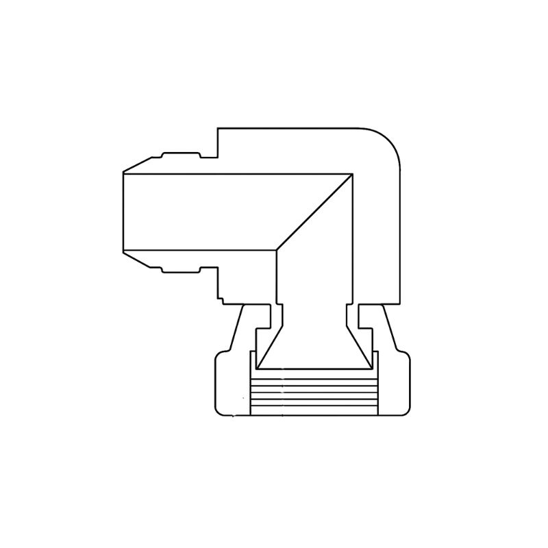
- A 90-degree elbow could be equivalent to 4-6 feet of hose.
- A tee (with flow through the branch) can be equivalent to over 8 feet of hose.
By adding up the equivalent lengths of all your fittings, you get a more accurate picture of the total system pressure drop.
Why Do Bends Matter So Much?
When fluid is forced to change direction abruptly, its flow becomes turbulent. The smooth, layered (laminar) flow is disrupted, creating chaotic eddies and swirls. Energy is consumed to create this turbulence, and that energy is stolen from the fluid pressure. This is why a 90-degree elbow has a much higher pressure drop than a straight fitting. A smooth, large-radius bent tube will always be more efficient than a sharp elbow fitting.
Conclusion
Properly sizing hydraulic fittings requires a simple but critical calculation: balancing flow rate and fluid velocity to select a size that minimizes pressure loss and heat, ensuring maximum system efficiency.
FAQ
What happens if a hydraulic fitting is too small?
It increases fluid velocity, causing pressure drop, heat buildup, and turbulence, which reduce system efficiency and damage components.
How do I calculate the right fitting size?
Use the formula A = Q / V, where Q is flow rate and V is velocity. Convert area into diameter, then match to a standard dash size.
What is the recommended velocity for suction lines?
Suction lines should be kept very low, around 2–4 ft/s, to prevent pump cavitation and ensure smooth operation.
Why is heat such a problem in hydraulic systems?
Excess heat shortens oil life, damages seals, reduces efficiency, and increases the risk of component failure.
How do dash sizes relate to fitting dimensions?
Dash sizes represent the hose’s internal diameter in sixteenths of an inch. For example, -8 equals 1/2 inch ID.
Do bends and elbows affect pressure drop?
Yes. Elbows, tees, and sharp bends create turbulence, adding pressure loss equivalent to several feet of straight hose.