A caliper can estimate diameter, but it cannot functionally verify whether a thread fits the specified mating envelope. One-piece fitting thread gauge inspection uses the correct plug, ring, pitch, or taper tool to answer a defined question about internal or external threads. The result is reliable only when the thread and gauge are clean, correctly aligned, within calibration, and evaluated against the specified standard and inspection plan.
Match the Gauge to the Thread Feature
Gauge selection begins with the complete thread callout, not with a fitting’s nominal size or appearance. Confirm whether the feature is internal or external, straight or tapered, and which form, pitch, class, and standard apply.
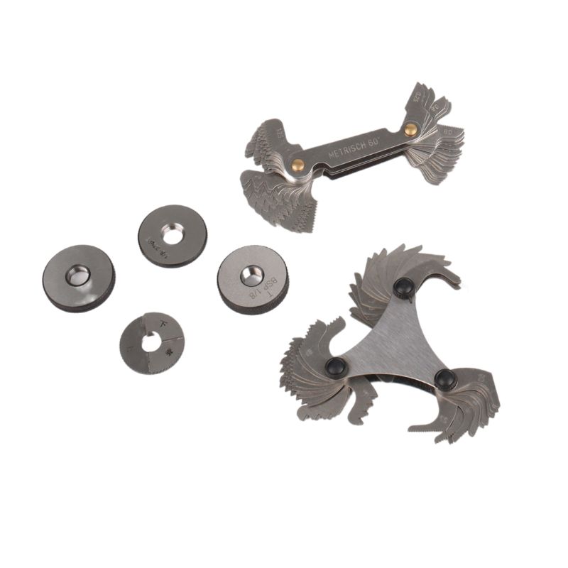
Plug, ring, pitch, and taper tools answer different questions
A thread plug gauge is normally used on an internal thread; a thread ring gauge is used on an external thread. GO and NO-GO members assess defined limits of functional size or form under the governing standard. A pitch gauge helps compare thread spacing but does not certify full thread geometry. Taper gauges or dedicated reference systems address features that a straight-thread gauge cannot evaluate.
The label “hydraulic thread gauge” is too broad for selection. JIC, ORB, NPT, NPTF, BSPP, BSPT, metric, and other connection families may use different forms, taper conditions, or sealing methods. Even when nominal sizes appear similar, a gauge from another standard can engage partially and still give a misleading result.
| Thread condition | Typical tool category | What it helps verify | What it does not prove |
| Internal straight thread | Specified GO/NO-GO plug gauge | Functional internal thread limits | Seat angle, O-ring groove, sealing-face condition |
| External straight thread | Specified GO/NO-GO ring gauge | Functional external thread limits | Mating component identity or pressure suitability |
| Suspected pitch during identification | Pitch gauge | Likely pitch or TPI for screening | Thread class, full form, final acceptance |
| Tapered thread | Standard-specific taper or working gauge | Defined taper-thread position or engagement | Correct sealant practice or port integrity |
| Damaged or contaminated thread | Visual and optical inspection before gauging | Burrs, dents, chips, coating buildup | Dimensional conformity by itself |
Verify the gauge identity before use
Read the gauge marking and its controlled record. Confirm type, size, pitch, form, class or designation, GO or NO-GO function, calibration status, and any master or setting relationship required by the quality system. Similar-looking gauges should remain clearly separated in storage.
Do not select a gauge by trial engagement. If the drawing callout is incomplete or conflicts with the purchase specification, stop and resolve the product identity first. Repeatedly trying different gauges can damage both the part and the inspection evidence.
Prepare the Part, Gauge, and Work Area
Many false failures come from dirt, dried preservative, chips, temperature differences, or poor handling rather than from the thread itself. Preparation should remove these variables without altering the feature.
Clean without changing the thread
Inspect the thread under controlled light before cleaning. Record visible dents, burrs, corrosion, coating buildup, embedded chips, or crossed starts. Then use the approved cleaning method for the material and finish. Do not chase the thread with a cutting tool, scrape a crest, or force a brush through it before the initial condition is documented.
Clean the gauge according to its care procedure. A particle on a plug flank or inside a ring can change feel, scratch the fitting, and transfer contamination to later parts. Check for rust, nicks, chipped edges, abnormal wear, and illegible identification. Remove a questionable gauge from service instead of treating its result as evidence.
Stabilize handling conditions
Keep the part and gauge in the specified inspection environment long enough to reduce avoidable temperature effects when dimensional sensitivity requires it. Hold the part so the thread axis can align naturally with the gauge. Do not clamp a thin or finished area in a way that deforms or scratches it.
Lubrication must follow the applicable gauge procedure. Some inspections call for a clean, defined lubricant; others may specify a dry condition. Uncontrolled oil can trap debris, change feel, or make results between inspectors inconsistent. Never add lubricant simply to make a gauge pass.
Apply GO and NO-GO Logic Correctly
GO and NO-GO gauging is a limit decision, not a contest to achieve maximum engagement. The governing thread standard and inspection plan define what the gauge should do and where the acceptance boundary lies.

Start square and use controlled hand force
Bring the gauge to the thread axis, allow the first thread to find its lead, and rotate smoothly by hand. If engagement feels eccentric, gritty, or abruptly tight, back off and inspect rather than applying more force. A tool handle is not permission to overcome resistance.
For a GO member, follow the specified engagement criterion. For a NO-GO member, follow the specified non-engagement or limited-engagement criterion. This article intentionally gives no universal number of turns: straight and tapered standards, gauge styles, thread classes, and inspection plans differ. Record the actual observation using the terminology required by the procedure.
Keep functional gauging separate from identification
A pitch gauge or tentative ring fit can help narrow an unknown thread, but final acceptance requires a gauge tied to a verified callout. Likewise, a GO result does not identify the sealing method. A fitting can have a conforming thread and the wrong seat angle, damaged sealing face, missing O-ring, or incorrect port relationship.
When tapered threads are involved, position, taper, truncation, and reference-plane logic may govern the result. Use the standard-specific gauge and instructions. Do not transfer the GO/NO-GO logic of a parallel thread to a tapered thread merely because both gauges screw onto the part.
Prevent Handling Errors That Create False Results
Most repeatability problems at the bench come from alignment, force, contamination, or an unclear stopping rule. A consistent technique matters as much as owning the correct gauge.
Recognize warning signs during engagement
Cross-starting often produces early resistance and visible tilt. Dirt may create a gritty or intermittent feel. A burr can catch at one angular position. Coating buildup may create progressive tightness. An out-of-round or damaged thread may engage differently after the part is rotated relative to gravity or support.
None of these sensations proves the cause. Stop, withdraw the gauge carefully, and inspect both surfaces. Clean again if the approved procedure permits, then repeat once using correct alignment. Repeated attempts that gradually “improve” the fit can burnish or remove the defect and invalidate the evidence.
Do not use force as an acceptance method
Pliers, wrenches, powered rotation, or impact are inappropriate unless a controlled standard-specific fixture explicitly calls for them. Excess force can wedge a ring, expand an internal feature, gall the surfaces, or damage an expensive gauge. It also turns a measurement into rework.
Inspector technique should be qualified through reference parts, work instructions, and repeatability checks. If two trained inspectors obtain different outcomes, quarantine the part and investigate the method, gauge condition, cleanliness, and acceptance wording before assigning product fault.
Control Calibration, Wear, and Traceability
A gauge result is only as defensible as the gauge’s known condition. Identification and an unexpired sticker alone may not be enough if the tool has been dropped, forced, corroded, or used on abrasive or dirty threads.
Link the tool to controlled status
The calibration system should identify the gauge, its applicable range or function, status, due date, and record. Ring gauges may require controlled setting against a master under the applicable procedure. Plug gauges need checks appropriate to their design. The laboratory or internal process determines intervals and methods based on use, risk, and requirements.
Before each use, perform the specified condition check. After a drop, jam, visible nick, or unexpected trend, remove the gauge from service and assess prior results according to the quality procedure. Do not polish or lap a working surface unless an authorized maintenance process controls the outcome and recalibration.
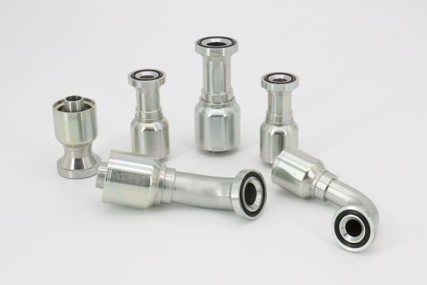
Watch for evidence of wear in the data
Increasing pass rates, a change in engagement feel, disagreement between duplicate gauges, or drift on reference parts can signal wear or contamination. Trend information is useful, but it does not replace calibration. A worn GO member may accept oversized or otherwise nonconforming threads; a damaged NO-GO member can create false rejection or acceptance depending on the condition.
Store gauges clean, protected, and separated from production tools. Caps, cases, corrosion protection, and controlled location reduce accidental damage and preserve identity. Storage oil must be removed or managed as the inspection procedure requires before the next use.
Record Results That Others Can Reproduce
“Thread checked” provides too little information for release, supplier feedback, or later complaint analysis. The record should connect the exact part feature to the exact gauge and decision rule.
Capture the complete inspection identity
Record the part number, drawing revision, batch or lot, sample identity, thread location, thread callout, gauge type, gauge ID, calibration status, inspection date, inspector, and result. For a fitting with more than one threaded end, name each connection unambiguously.
If the procedure permits recording actual engagement observations, use its required format and reference plane. Avoid free-text statements such as “almost passed.” Note dirt, burrs, coating buildup, or damage as separate visual findings; do not hide them inside the gauge result.
Escalate ambiguous results
When a gauge stops unexpectedly, gives inconsistent repeats, or conflicts with another verified tool, contain the sample and related stock. Preserve the part and gauge condition, then investigate alignment, cleanliness, gauge wear, callout accuracy, and process history. Do not average pass and fail outcomes.
Photographs can orient the defect or thread end, but they cannot prove functional gauge acceptance. The final disposition should cite the controlled requirement and any authorized reinspection or rework method.
Use a Thread-Gauging Workflow for Every Batch
A short workflow helps receiving teams apply the same logic to each sample while keeping identification, gauging, and sealing review distinct.
Bench sequence
- Verify the part number, drawing revision, batch, and exact thread callout.
- Select the specified plug, ring, pitch, or taper gauge; confirm markings and status.
- Inspect and clean the part and gauge without changing the thread.
- Set the required lubrication and environmental condition.
- Align the GO gauge squarely and apply only the defined hand technique.
- Apply the NO-GO or taper check exactly as the governing procedure states.
- Stop on abnormal resistance; never force the gauge or use it to remove a burr.
- Record gauge ID, feature, result, and separate visual findings.
- Contain uncertain results and preserve traceability until disposition.
The sequence does not approve the sealing seat, hose compatibility, crimp specification, material, or complete assembly. Add those checks under their own controlled plans when the purchasing or release decision requires them.
Conclusion
Thread gauging is dependable when the question, tool, technique, and acceptance rule all match. Select the gauge from the complete thread callout, prepare both surfaces, align by hand, and stop when resistance suggests dirt, damage, or misalignment. GO and NO-GO outcomes must follow the named standard and inspection plan; there is no universal engagement count. Calibration status, gauge condition, and storage protect the credibility of every result, while complete records preserve batch and feature traceability. Keep identification, functional size, and sealing approval as separate decisions so one passing check does not conceal another risk. Before completing one-piece fitting thread gauge inspection, verify the drawing revision, thread identity, gauge ID, calibration record, cleaning and lubrication conditions, actual observation, and separate sealing-interface checks.
Frequently Asked Questions
Should thread gauges be lubricated before inspection?
Only when the applicable gauge procedure specifies lubrication. Use the defined type and amount because uncontrolled oil can trap particles, change feel, and make results inconsistent.
What should I do if a clean gauge fails on a dirty thread?
Document the original condition, clean the thread using the approved method, and reinspect if the procedure allows it. Do not cut, scrape, or force the thread simply to obtain a pass.
How can I tell whether a thread gauge is worn?
Use calibration, condition checks, masters or reference parts where required, and trend data. A visual glance alone cannot establish that the working geometry remains within its controlled limits.
Why does a gauge engage only partway?
Possible reasons include the wrong gauge, misalignment, dirt, burrs, coating buildup, thread damage, taper logic, or a nonconforming thread. Stop and isolate the variables rather than forcing further engagement.
Can I use a thread gauge after its calibration date?
Not for controlled acceptance unless the quality system has formally extended or re-established its status. Quarantine the gauge and assess any affected results according to the calibration procedure.