A thread can pass its gauge and still connect to the wrong or damaged sealing seat. One-piece fitting seat gauge inspection must evaluate the interface that actually stops fluid: its profile, angle, contact location, concentricity, finish, and cleanliness. Thread engagement positions the parts, but it does not prove that two flare or cone surfaces match.
Separate Thread Fit From Sealing-Seat Fit
Thread and seat are related features with different jobs. The thread draws and retains the connection; the seat, face seal, tapered thread, or another defined interface creates the fluid boundary.
A passing thread result has a narrow meaning
A plug or ring gauge can confirm specified thread characteristics when used correctly. It cannot establish the seat angle, profile, diameter, finish, runout, or freedom from damage. A component from another connection family may screw together partly or fully yet place the wrong surfaces in contact.
Record thread and seat results separately. This prevents a receiving report from stating “connection passed” when only one feature was measured. It also helps investigators distinguish leakage caused by seat damage from problems such as wrong thread form, O-ring condition, assembly load, port damage, or hose-end assembly.
Identify the intended sealing interface first
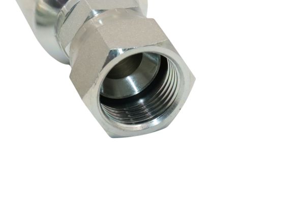
Review the part number, drawing, connection callout, and mating component before selecting a seat gauge. Determine whether the connection uses a flare, cone, flat face with an elastomer, O-ring boss, tapered thread, bonded seal, or another design. A visual resemblance is only a screening clue.
If the drawing names a thread but omits the associated sealing detail, request clarification. Do not choose a familiar seat angle from memory. The safe inspection plan starts with an explicit interface definition and then assigns the gauge or comparator that represents it.
Know Which Connections Depend on a Machined Seat
Many flare and cone connections rely on controlled contact between two machined profiles. Other designs seal on an O-ring face, groove, washer, or thread. Seat inspection matters most where the machined profile forms or supports the contact.
Contact geometry governs the review
A seat may require control of angle, cone profile, contact diameter, depth, concentricity, and surface condition. Some designs place contact near an edge; others use a broader band. The drawing and standard determine the intended relationship, not the inspector’s expectation of where a witness mark “should” appear.
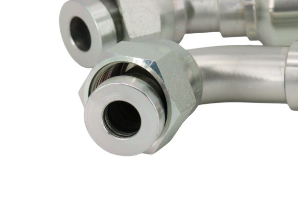
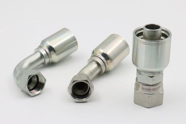
Do not confuse an external flare, internal cone, inverted seat, or flat face. The same nominal thread size can coexist with different sealing concepts. Catalog names and part photographs should be confirmed against controlled technical data before a gauge touches the part.
The mating part is part of the decision
A conforming fitting seat can still leak against a damaged, contaminated, or incorrect mating component. Conversely, a mismatch may produce a narrow apparent contact mark without achieving a reliable seal. Inspection should preserve the distinction between component conformity and assembly compatibility.
When replacement parts are evaluated, verify both sides: thread standard, seat family, male/female relationship, profile, seal location, material, and application requirements. Never infer complete interchangeability from engagement or from a single seat impression.
Verify Seat Angle and Profile With the Right Method
The inspection method should match the question and the feature’s accessibility. A dedicated functional seat gauge, optical comparator, profile measurement, controlled template, or drawing-based dimensional method may each be appropriate under a defined plan.
Dedicated gauges need a defined purpose
A seat gauge may indicate angle relationship, contact, depth, or profile, depending on its design. Confirm its part number, range, master, calibration status, and use instruction. A tool made for one connection family should not be used as a generic “cone gauge.”
Apply only the specified contact force. Pressing, twisting, or rocking a hardened gauge against the seat can scratch the sealing path or create a misleading witness. If a transfer medium or contact indication is allowed, use only the approved material and method, then clean the part as required. An improvised marker can contaminate the seat or conceal fine damage.
Optical and dimensional methods need references
Optical comparison can reveal profile and angle without direct contact, but fixturing, focus, edge detection, and datum alignment affect the result. A shadow that represents a burr or coating buildup is not necessarily the true machined profile. Dimensional measurements must reference the datums and definitions on the drawing.
No method should generate an angle merely because software can fit a line. Confirm the evaluated surfaces, excluded defects, measurement range, and uncertainty are suitable. If the feature cannot be accessed reliably, document the limitation and use an approved alternative rather than reporting an unsupported pass.
Inspect Surface Damage, Concentricity, and Contamination
Correct nominal geometry does not clear a scratched, dented, eccentric, or dirty seat. Surface and alignment findings must be reviewed with the profile result.
Local defects can interrupt the contact path
A scratch crossing the expected contact band may create a leak path. A dent can shift contact to a small area. Chatter, torn material, or a burr can hold mating surfaces apart. Embedded chips and dried residue can create a false impression during gauging and later enter the hydraulic system.
Use controlled light from several angles and suitable magnification. Describe the defect by type, location, direction, and relation to the sealing band. Do not approve the seat by touch, and do not drag a probe across it. A roughness value cannot automatically clear an isolated scratch, while visible machining lay is not automatically a defect if it meets the controlled requirement.
Concentricity links the seat to the connection axis
A seat can have the specified profile locally yet be offset or tilted relative to the thread or fitting axis. That condition may create uneven contact, side loading, or misleading gauge impressions. The drawing should define the relevant datum and tolerance when this relationship is critical.
Do not judge concentricity from a handheld photograph. Use the specified fixture and measurement method. Swivel components require care because movement, clearance, and part orientation can affect setup; the inspection plan should state which component position and datum apply.
| Seat finding | Possible consequence | Verification method |
| Wrong angle or profile | Edge contact, incomplete seating, incompatible connection | Dedicated gauge, comparator, or drawing-based profile measurement |
| Scratch across contact path | Potential leakage route or seal damage | Controlled light, magnification, and specified surface criteria |
| Dent, burr, or raised material | Local stand-off and uneven contact | Non-contact visual inspection plus approved dimensional review |
| Eccentric or tilted seat | Uneven load and partial contact | Datum-based runout or concentricity method from the drawing |
| Contamination or coating buildup | False gauge result, incomplete contact, particle release | Approved cleaning followed by repeated visual and functional inspection |
Protect the Seat During Inspection
Inspection loses value if it changes the surface. Handling, cleaning, fixturing, and gauge contact should all protect the sealing path.
Preserve evidence before cleaning
For incoming defects or complaints, photograph the fitting and seat before removing residue when safe. Record part number, batch, orientation, and packaging condition. Dirt may be the cause, a result of handling, or unrelated, but cleaning it first removes information needed for containment.
After documentation, use the approved method that will not attack the material, coating, or elastomer. Avoid abrasive pads, picks, files, and uncontrolled polishing. Blow-off procedures must control particle direction and compressed-air hazards. Confirm the seat is dry or conditioned as the inspection method requires.
Use fixtures and gauges gently
Support the fitting on non-damaging surfaces and keep hard tools away from the seat. Insert gauges squarely and without impact. Never use the seat gauge to remove a burr, prove that a scratch is “only cosmetic,” or reshape the profile.
If the gauge contacts unexpectedly, stop and inspect. Repeated rotation can burnish a high spot and change the evidence. Any approved rework such as lapping must define material-removal limits, geometry verification, cleaning, and reinspection; it is not a general remedy for unknown seat damage.
Record Seat Findings as Reproducible Evidence
A useful record tells another inspector which interface was checked, with what tool, against which revision, and what was observed. “Seat OK” is too vague for a controlled release.
Link every result to the feature and method
Record the part and batch, drawing revision, connection end, seat callout, gauge or instrument ID, calibration status, setup, inspector, and result. For optical measurements, retain the approved image or data file where the quality system requires it. For localized damage, include an overview and close-up without allowing a scale to touch the seat.
Keep surface condition, profile, concentricity, cleanliness, and thread gauge results in separate fields. This structure shows which requirement failed and prevents one passing result from masking another. If a sample cannot be measured because of access or damage, record “not evaluated” with the reason rather than a pass.
Contain uncertainty by batch
Segregate questionable parts and preserve their labels. Determine whether the finding is isolated, repeated by cavity or tool position, limited to one batch, or associated with handling. Sampling and disposition must follow the approved quality plan rather than an improvised number.
Photos and gauge marks can support an investigation but do not establish root cause alone. Review machining, finishing, packaging, and mating-component evidence before assigning cause or approving rework.
Follow a Seat-Inspection Decision Path
A decision path keeps the sealing interface first and prevents thread results from ending the inspection too early.
From identity to release
- Confirm the part number, drawing revision, connection family, and intended sealing method.
- Identify the exact seat feature and its profile, datum, finish, and cleanliness requirements.
- Preserve photographs and batch identity before cleaning when investigating a defect.
- Inspect for scratches, dents, burrs, coating, corrosion, and debris under controlled light.
- Select the dedicated gauge, comparator, or dimensional method named by the inspection plan.
- Verify tool identity and calibration, fixture the part without touching the sealing path, and measure without force.
- Evaluate profile, angle, contact indication, concentricity, and surface findings separately.
- Record the thread result separately and verify the mating component when compatibility is part of the decision.
- Contain any uncertain or failed part until approved disposition and reinspection are complete.
This path confirms the component features specified in the plan. It does not establish complete hose compatibility, crimp data, system pressure suitability, or safe installation; those decisions need their own evidence.
Conclusion
Seat inspection must begin at the sealing interface, not at the thread. A thread gauge can pass while the cone or flare has the wrong profile, an interrupted contact path, contamination, or alignment error. Quality teams should identify the connection family, use the controlled drawing, protect the seat from inspection damage, and select a dedicated or optical method with known calibration and setup. Surface damage, profile, concentricity, cleanliness, and thread results belong in separate records. Where any requirement is unclear, contain the part rather than approving it from appearance, engagement, or an improvised contact mark alone. Before approving one-piece fitting seat gauge inspection, prepare the current callout, mating-interface definition, gauge identity, datum method, surface evidence, batch linkage, and approved acceptance criteria.
Frequently Asked Questions
Can one seat-angle gauge cover every hydraulic fitting family?
No. Seat profiles and gauge purposes differ among connection families. Select the gauge from the verified callout and its controlled instructions rather than from nominal thread size.
Is a visible scratch on a fitting seat always a failure?
It requires evaluation against the specified contact path and surface criteria. Location, direction, raised edges, depth, and geometry matter, and a visual judgment alone may be insufficient.
Can a damaged seat be lapped until it seals?
Only under an approved rework process. Lapping can change angle, contact diameter, finish, and material condition, so defined limits, cleaning, and full reinspection are necessary.
How can the thread pass while the seat fails?
The features perform different functions and have different geometry. A conforming thread can position parts whose seat angles, profiles, finish, or sealing methods do not match.
Is visual inspection enough for a sealing seat?
Visual inspection is valuable for damage and contamination but usually cannot prove controlled angle, profile, or concentricity. Use the drawing’s required gauge or measurement method for those characteristics.