Choosing the right hydraulic cylinder is crucial for your machine’s performance and lifespan. With so many options, how do you pick the perfect one? This guide simplifies the process. We’ll walk you through matching cylinder parameters like force, speed, and mounting style to specific jobs on different machines, from construction diggers to farm tractors.
Understanding the Basics: Key Hydraulic Cylinder Parameters
Force: The Muscle of the Cylinder
Force is often the primary consideration. It’s the amount of push or pull the cylinder can exert. This is determined by the hydraulic system’s pressure and the cylinder’s bore size (the internal diameter of the cylinder barrel). The relationship is straightforward: Force = Pressure x Area. The area here is the surface area of the piston inside the cylinder. For pushing (extending), the full piston area is used. For pulling (retracting), the area is reduced by the cross-sectional area of the piston rod.
- Calculating Push Force: Force (lbs) = Pressure (psi) x π x (Bore Diameter/2)²
- Calculating Pull Force: Force (lbs) = Pressure (psi) x π x \[(Bore Diameter/2)² – (Rod Diameter/2)²]
Always select a cylinder with a force rating slightly higher than your maximum requirement to provide a safety margin, typically 10-25% extra. Consider both static load (holding) and dynamic load (moving) requirements. Don’t forget potential shock loads, which can momentarily spike the force needed.
Speed: How Fast Does It Move?
Cylinder speed refers to how quickly the piston rod extends or retracts. This is determined by the flow rate of hydraulic fluid supplied to the cylinder (measured in gallons per minute, GPM) and the volume of the cylinder chamber being filled. A larger bore cylinder requires more fluid to move the same distance, so it will move slower at the same flow rate compared to a smaller bore cylinder.
- Calculating Extension Speed: Speed (inches/min) = (Flow Rate (GPM) x 231) / (π x (Bore Diameter/2)²)
- Calculating Retraction Speed: Speed (inches/min) = (Flow Rate (GPM) x 231) / (π x \[(Bore Diameter/2)² – (Rod Diameter/2)²])
Notice that retraction speed is usually faster than extension speed because the rod takes up space, reducing the volume that needs to be filled. Ensure the speed matches the operational requirements of your machine. Too slow can hinder productivity; too fast can cause jerky movements or excessive shock.
Stroke Length: How Far Does It Reach?
Stroke length is the total distance the piston rod can travel from fully retracted to fully extended. This is a critical dimension determined entirely by the application’s needs – how far does a component need to move? Measure the required travel distance accurately. Consider potential obstructions and ensure the chosen stroke provides the full range of motion needed without bottoming out or overextending. Remember that the overall length of the cylinder (retracted and extended) will depend on the stroke length and the cylinder’s construction (including mounting).
Pressure Rating: Handling the System’s Power
Every cylinder has a maximum operating pressure rating. This indicates the highest hydraulic pressure the cylinder is designed to withstand safely during continuous operation. Exceeding this pressure can lead to seal failure, component deformation, or even catastrophic failure (bursting). Always choose a cylinder with a pressure rating equal to or, ideally, slightly higher than your hydraulic system’s maximum operating pressure. Typical pressure ranges for mobile equipment are 2000-3500 psi, while industrial applications can range from 1500 psi to 5000 psi or more.
Bore Size and Rod Diameter: The Core Dimensions
We’ve mentioned these, but they are fundamental. The bore size (internal diameter) directly impacts force and speed. A larger bore means more force but slower speed for a given pressure and flow. The rod diameter affects pull force, retraction speed, and column strength (resistance to buckling under compressive load, especially important for long-stroke cylinders). The ratio between bore and rod diameter is also key. A large rod diameter relative to the bore (differential cylinder) results in faster retraction but lower pull force.
Mounting Styles: Connecting to the Machine
How the cylinder attaches to the machine is critical for stability and proper force transfer. Common mounting styles include:
- Clevis Mounts: Allow pivoting in one plane. Good for applications where the load path might change slightly.
- Trunnion Mounts: Allow pivoting around the trunnion axis, often mounted mid-barrel or at the head/cap.
- Flange Mounts (Head or Cap): Provide rigid mounting for straight-line force transfer.
- Foot Mounts: Lugs welded to the barrel for mounting parallel to a surface.
- Spherical Bearings: Allow pivoting in multiple planes, accommodating misalignment.
Choose a mounting style that suits the load type (tension, compression, side load) and the movement required. Ensure the mounting hardware and the machine structure can handle the forces involved.
Construction Equipment: Excavators and Loaders
Boom Cylinders: The Heavy Lifters
Boom cylinders typically provide the primary lifting force for the excavator’s or loader’s main arm structure. They handle the weight of the arm, bucket, and the load being lifted.
- Force Requirements: Very high push force is needed to lift heavy loads. These are often the largest cylinders on the machine. Pressure ratings are typically high (e.g., 3000-5000 psi). Bore sizes are substantial to generate the necessary force.
- Stroke Length: Must accommodate the full vertical range of motion required for the boom.
- Speed: Moderate speed is usually sufficient, prioritizing smooth control over rapid movement. Flow control valves are essential.
- Mounting: Heavy-duty clevis or trunnion mounts are common to allow pivoting as the boom raises and lowers. Spherical bearings are often used at the pin connections to handle slight misalignments under heavy load.
- Construction: Robust construction with high-strength steel barrels and rods. Induction-hardened rods with heavy chrome plating are standard to resist damage and corrosion. Advanced sealing systems are needed to handle high pressure and prevent external contamination.
- Special Features: Load-holding valves (counterbalance valves) are critical to prevent the boom from dropping if hydraulic pressure is lost. Integrated cushioning can reduce shock at the end of stroke.
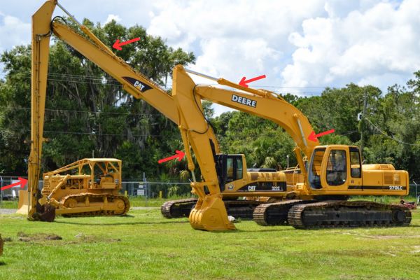
Arm (Stick) Cylinders: Extending the Reach
The arm or stick cylinder controls the movement of the dipper arm, extending the reach of the bucket.
- Force Requirements: Significant push and pull forces are needed for digging and positioning. Bore sizes are typically smaller than boom cylinders but still substantial.
- Stroke Length: Must allow the arm to move through its full range, from close-in digging to maximum reach.
- Speed: Often requires faster operation than the boom for efficient digging cycles. Needs precise control.
- Mounting: Usually clevis or pin-eye mounts at both ends to allow pivoting relative to the boom and the bucket linkage.
- Construction: Similar heavy-duty construction as boom cylinders, designed to withstand shock loads during digging. Effective rod wipers and seals are crucial due to exposure to dirt and debris.
- Special Features: Cushioning is important to prevent harsh impacts at the end of stroke. Load-holding valves may be incorporated.
Bucket Cylinders: Controlling the Bite
Bucket cylinders control the tilting or curling action of the bucket for digging, loading, and dumping.
- Force Requirements: High force is needed, especially during breakout when digging into compacted material. Both push (curl) and pull (dump) forces are important.
- Stroke Length: Relatively shorter stroke compared to boom and arm cylinders, matching the required rotation angle of the bucket.
- Speed: Needs to be responsive for quick bucket adjustments during the digging cycle.
- Mounting: Typically pin-eye or clevis mounts connecting to the arm and the bucket linkage.
- Construction: Must be extremely robust to handle high impact and abrasive wear. Rod protection (guards or boots) might be considered in very abrasive conditions. High-performance seals are essential.
- Special Features: Often subject to the highest shock loads on the machine. Cushioning can be beneficial. Hardened pins and bushings at mounting points are critical.
Selection Table Example (Excavator):
| Application | Primary Force | Speed Need | Stroke | Mounting | Key Feature |
| Boom | High Push | Moderate | Long | Clevis/Trunnion | Load Holding |
| Arm/Stick | High Push/Pull | Moderate/Fast | Long | Clevis/Pin-Eye | Durability |
| Bucket | High Push/Pull | Fast | Short/Medium | Clevis/Pin-Eye | Shock Resistance |
Agricultural Machinery: Tractors and Harvesters
Tractor Three-Point Hitch Lift Cylinders: The Implement Interface
The three-point hitch is the primary way tractors connect to and control implements like plows, planters, and cultivators. Lift cylinders raise and lower the hitch arms.
- Force Requirements: Must lift the heaviest compatible implement. Force requirements vary significantly based on tractor size (from small utility tractors to large row-crop models). Push force is primary.
- Stroke Length: Needs to provide sufficient lift height for ground clearance and implement operation.
- Speed: Moderate speed is typical, but smooth, controllable movement is crucial, especially when lowering implements.
- Mounting: Often integrated directly into the tractor’s rear axle housing or frame, using specialized trunnion or clevis arrangements.
- Construction: Needs to be robust and reliable. Sealing must withstand dust and dirt. Corrosion resistance is important due to potential fertilizer/chemical exposure.
- Special Features: Position control is a key feature, allowing the operator to set and maintain a specific implement height or depth. Draft control (adjusting depth based on pulling force) often involves sensing within the hitch linkage, influencing cylinder operation. Load holding is essential.
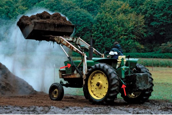
Tractor Steering Cylinders: Guiding the Way
Most modern tractors use hydrostatic steering systems with hydraulic cylinders acting on the steering linkage or axle.
- Force Requirements: Sufficient force to turn the wheels, especially under load or with large front-mounted implements. Force needs vary with tractor size and tire type.
- Stroke Length: Matched to the steering geometry to provide the required turning angle lock-to-lock.
- Speed: Must allow for responsive steering control at various operating speeds.
- Mounting: Typically clevis or ball-joint ends, connecting the axle or steering knuckles to the tractor frame.
- Construction: High cycle life is critical due to constant steering adjustments. Must be well-sealed against dust and moisture. Reliability is paramount for safety.
- Special Features: Often double-rod cylinders for equal displacement and speed in both directions. May incorporate position sensors for auto-steering (GPS guidance) systems.
Combine Harvester Header Lift Cylinders: Gathering the Crop
Combine harvesters use cylinders to raise and lower the header (the front part that cuts and gathers the crop).
- Force Requirements: Must lift the weight of the header, which can be substantial, especially for wide corn or draper headers.
- Stroke Length: Sufficient to lift the header for transport and adjust cutting height during operation.
- Speed: Moderate speed with smooth control for precise cutting height adjustments.
- Mounting: Typically clevis or trunnion mounts connecting the header frame to the combine’s feeder house.
- Construction: Must withstand vibration and dusty conditions. Good sealing is essential to prevent contamination from chaff and dust.
- Special Features: Often work in conjunction with an accumulator system for flotation (allowing the header to follow ground contours). Position sensors are used for automatic header height control. Load holding is critical.
Material Handling: Forklifts and Telehandlers
Forklift Lift Cylinders: Reaching New Heights
These cylinders, often integrated directly into the mast structure, raise and lower the forks.
- Force Requirements: Must lift the forklift’s rated capacity. Force is primarily push.
- Stroke Length: Determines the maximum lift height of the forks. Can be single-stage or multi-stage (telescopic) for high lifts.
- Speed: Smooth, controlled ascent and descent are critical for safety and load stability. Descent speed is often regulated by flow control valves.
- Mounting: Highly specialized mounting integrated within the mast channels. Often act directly on mast sections or via lift chains.
- Construction: High precision is needed for smooth mast operation. Excellent sealing is required to prevent leaks, especially important for indoor use. Rod finish must be smooth to protect seals during rapid cycling.
- Special Features: Load-lowering control valves are essential safety features. Multi-stage telescopic cylinders are common for high-lift masts, requiring intricate internal sealing and guiding systems.
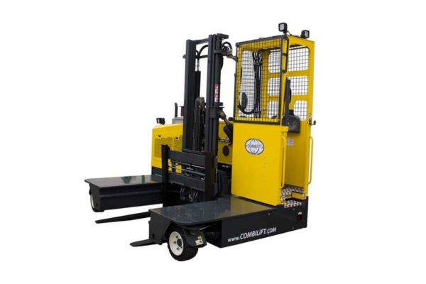
Forklift Tilt Cylinders: Angling the Load
Typically, two cylinders are mounted between the mast and the forklift frame, allowing the mast (and forks) to tilt forward and backward.
- Force Requirements: Sufficient force to tilt the rated load smoothly. Both push (tilt back) and pull (tilt forward) forces are important.
- Stroke Length: Relatively short, corresponding to the required tilt range (typically a few degrees forward and back).
- Speed: Moderate speed with fine control for precise load positioning.
- Mounting: Usually trunnion or clevis mounts to allow pivoting as the mast tilts.
- Construction: Robust construction to handle load forces. Must provide stable positioning with minimal drift.
- Special Features: Good load-holding capability is needed to maintain the set tilt angle. Cushioning can provide smoother stops at the end of the tilt range.
Telehandler Boom Lift and Extension Cylinders: Reaching Out
Telehandlers (telescopic handlers) use cylinders for lifting the boom and extending/retracting its telescopic sections.
- Boom Lift Cylinders: Similar to loader boom cylinders but often longer stroke. High push force required. Need excellent load holding and smooth control.
- Boom Extension/Retraction Cylinders: Located inside the boom sections. Can be single cylinders with complex chain/cable arrangements or multi-stage telescopic cylinders. Require careful synchronization if multiple cylinders are used. Must handle high internal pressures and provide smooth extension/retraction.
- Force Requirements: Extension cylinders need force to push out boom sections, often carrying load. Lift cylinders handle the main lifting.
- Stroke Length: Extension cylinder stroke determines the telehandler’s reach. Lift cylinder stroke determines elevation.
- Mounting: Lift cylinders typically use heavy-duty clevis/trunnion mounts. Extension cylinders are internally mounted.
- Construction: High-strength materials and precision manufacturing are essential, especially for internal extension cylinders. Advanced sealing is critical to prevent internal leakage between telescopic stages.
- Special Features: Load-holding valves on all cylinders are critical safety items. Extension cylinders often incorporate sequencing valves. Position sensors may be used for load monitoring systems.
Industrial Machinery: Presses and Injection Molding
Hydraulic Press Main Ram Cylinders: Applying the Force
The main ram cylinder delivers the primary pressing force.
- Force Requirements: Can range from a few tons to thousands of tons, depending on the press size and application. Push force is dominant.
- Stroke Length: Varies greatly based on the press design and the parts being formed. Can range from inches to several feet.
- Speed: Often requires variable speed control – rapid advance, controlled pressing speed, and rapid retract. Proportional valves are common.
- Mounting: Typically heavy flange mounts (head or cap end) or sometimes trunnion mounts for specific press designs. Must ensure rigid alignment.
- Construction: Extremely robust construction using high-strength materials. Precision machining for smooth operation and minimal leakage. Barrel walls are thick enough to handle high pressures (often 3000-5000 psi or more).
- Special Features: High precision control of position and force is often required. May incorporate linear position sensors (LVDTs or magnetostrictive sensors). High-quality, low-friction seals are needed for accurate force control. Safety features like redundant load holding are critical.
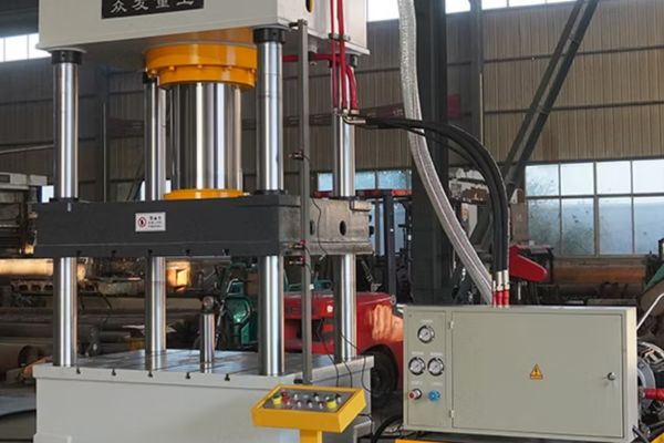
Hydraulic Press Return/Pullback Cylinders: Resetting the Cycle
Smaller cylinders are often used to retract the main ram quickly after the pressing stroke.
- Force Requirements: Sufficient force to overcome the weight of the ram and tooling, and any residual process forces. Pull force is primary.
- Stroke Length: Matches the main ram stroke.
- Speed: Typically requires fast retraction to minimize cycle time.
- Mounting: Various styles, often flange or clevis, depending on press design.
- Construction: Designed for speed and reliability. May operate at lower pressure than the main ram.
- Special Features: Synchronization with the main ram control is essential.
Injection Molding Clamp Cylinders: Holding the Mold
These cylinders provide the high force needed to keep the two halves of the injection mold tightly closed against the pressure of the molten plastic being injected.
- Force Requirements: Very high push force (clamp tonnage) is the defining parameter. Must maintain this force consistently throughout the injection and cooling phases.
- Stroke Length: Sufficient to open the mold wide enough for part ejection and potential robotic access.
- Speed: Requires fast opening and closing speeds for short cycle times, but often with controlled deceleration at the end of stroke to protect the mold.
- Mounting: Integrated into the machine’s clamp unit structure, often using tie bars or specialized flange mounts.
- Construction: Massive, robust construction. Precision is key for platen parallelism. Must withstand high cycle rates (often millions of cycles). Low-friction seals are important for speed and efficiency.
- Special Features: Often part of complex toggle mechanisms or direct hydraulic clamp systems. May incorporate position sensors for precise control of clamp position and speed profiles. Energy efficiency is increasingly important.
Matching Parameters to Applications: A Practical Approach
Step 1: Define the Application Requirements
Start by clearly defining what the cylinder needs to do:
- Function: What is the primary task? (Lifting, tilting, clamping, steering, extending, etc.)
- Load: What is the maximum weight or resistance the cylinder must move or hold? Consider static and dynamic loads, and potential shock loads.
- Travel Distance: How far does the driven component need to move? (This defines the stroke length).
- Speed: How fast does the movement need to happen? Is precise speed control needed?
- Cycle Rate: How often will the cylinder operate? (e.g., continuous duty, intermittent, infrequent).
- Operating Environment: What are the conditions? (Temperature extremes, dust, moisture, corrosive chemicals, potential impacts).
- Available Space: What are the physical constraints for the cylinder’s retracted and extended length, and diameter?
- System Pressure & Flow: What is the available hydraulic pressure and flow rate from the machine’s power unit?
Step 2: Calculate Key Parameters
Using the requirements defined above and the formulas from Section 1, calculate the necessary parameters:
- Required Force: Calculate push and pull force needed. Add a safety margin (e.g., 25%).
- Required Bore Size: Based on the required force and available system pressure, calculate the minimum bore size. Choose the next standard size up.
- Required Rod Diameter: Consider pull force requirements and buckling potential (especially for long strokes under compression). Select an appropriate standard rod size for the chosen bore.
- Required Speed: Calculate the speed based on available flow and the chosen bore/rod size. Does it meet the application need? If not, you may need to adjust flow rate (valve settings) or reconsider bore size.
- Stroke Length: Directly from the application’s travel distance requirement.
Step 3: Select Mounting Style and Construction Features
- Mounting: Choose a style (clevis, trunnion, flange, etc.) that suits the load path and movement required. Ensure the mounting can handle the calculated forces.
- Seals: Select seal materials (Nitrile, Urethane, Viton, PTFE) based on temperature, fluid type, pressure, and environmental conditions.
- Materials: Choose barrel and rod materials (e.g., steel grades, stainless steel) and rod plating (chrome, nickel-chrome) based on strength requirements and corrosion resistance needs.
- Special Features: Determine if cushioning, load-holding valves, position sensors, or special coatings are needed based on the application’s safety and control requirements.
Example Selection Table (General Guide)
This table provides a very general starting point. Always refer to manufacturer specifications and consult with experts for critical applications.
| Feature | High Force / Low Speed (e.g., Press Ram) | High Speed / Moderate Force (e.g., Lifter Arm) | Precision Control (e.g., Grader Blade) | Harsh Environment (e.g., Mining Bucket) |
| Bore Size | Large | Medium | Medium/Small | Large/Medium |
| Pressure | High (3000+ psi) | Moderate (2000-3000 psi) | Moderate | High |
| Rod Diameter | Standard or Large | Standard | Standard | Large/Heavy Duty |
| Mounting | Flange, Heavy Trunnion | Clevis, Pin-Eye | Clevis, Spherical Bearing | Heavy Clevis/Trunnion |
| Seals | High Pressure, Low Friction | High Cycle, Standard Temp | Low Leakage, Low Friction | Heavy Duty Wipers, Abrasion Resistant |
| Features | Position Sensor, Proportional Control | Cushioning, High Flow Ports | Load Holding, Position Sensor | Rod Protection, Advanced Coatings |
Step 4: Verify and Document
Double-check all calculations and selections. Ensure the chosen cylinder fits within the available space (check retracted/extended lengths and pin-to-pin dimensions). Consult manufacturer catalogs or technical support if unsure. Document the final selection, including part numbers and specifications, for future reference and maintenance.
Conclusion
Selecting the right hydraulic cylinder involves more than just matching basic specifications. It requires understanding the specific demands of the application, from the forces involved to the operating environment. By carefully considering parameters like force, stroke, speed, mounting style, pressure rating, and construction features, and matching them to the job at hand – whether it’s lifting a boom, tilting a blade, or clamping a mold – you can ensure optimal performance, safety, and longevity for your machinery.
If you need a customized hydraulic cylinder for your application, tell me the details of your needs and we can produce samples to give you the best service!
FAQ
What happens if I use a cylinder with too low a force rating?
The cylinder may stall, be unable to move the load, or move very slowly. In extreme cases, it could lead to internal damage or failure if overloaded repeatedly.
Can I use a higher-pressure cylinder in a lower-pressure system?
Yes, generally this is safe. The cylinder is built to handle more pressure than the system provides. However, don’t use a lower-pressure rated cylinder in a higher-pressure system.
What is cylinder cushioning and when do I need it?
Cushioning is a feature that slows the piston down at the very end of its stroke (extend or retract) to prevent harsh impacts. It’s needed in applications with high speeds or heavy masses to reduce shock, noise, and wear.
How important is the hydraulic fluid type for cylinder selection?
Very important. Seal materials must be compatible with the specific hydraulic fluid being used (e.g., standard mineral oil, biodegradable fluids, water glycol). Using incompatible seals will cause them to fail quickly.
What does ‘NFPA Interchangeable’ mean for a cylinder?
This means the cylinder’s mounting dimensions and basic envelope size conform to standards set by the National Fluid Power Association (NFPA). This allows cylinders from different manufacturers adhering to the standard to be physically interchangeable for mounting purposes.
Why is rod finish important?
A smooth, hard rod surface (typically chrome-plated) is essential for seal life. Scratches, corrosion pits, or roughness on the rod will quickly damage the seals as the rod moves in and out, causing leaks.