In hydraulic systems, every component plays a crucial role in ensuring efficiency, durability, and reliability, and guide rings are no exception. Often overlooked, these precision-engineered parts are essential for maintaining alignment and preventing wear within hydraulic cylinders. One particularly intriguing feature is their split design, which may seem unconventional at first glance but offers significant performance advantages. From easing installation to accommodating thermal expansion and manufacturing tolerances, the split configuration is a smart solution to complex engineering challenges. This article takes a closer look at why split guide rings are widely adopted in hydraulic cylinders and how this subtle design choice can make a major difference in system performance and longevity.
Understanding Hydraulic Cylinder Guide Rings
Hydraulic cylinder guide rings, also known as wear rings or support rings, are non-metallic components that play a crucial role in the efficient operation of hydraulic systems. These specialized components are designed to guide the linear motion of pistons or piston rods within hydraulic cylinders, preventing direct metal-to-metal contact between moving parts while absorbing side loads and maintaining proper alignment throughout the cylinder’s operational cycle.
Function and Importance
The primary function of guide rings is to provide a stable bearing surface that centers the piston and rod dynamic surfaces within the cylinder bore. By creating a controlled interface between moving components, guide rings effectively distribute transverse forces that would otherwise cause uneven wear, misalignment, or premature failure of the hydraulic system. This guidance function is particularly critical in applications involving high pressures, heavy loads, or extended duty cycles where even minor misalignments can lead to significant performance degradation.
Beyond their guidance role, these components serve several additional purposes that contribute to overall system integrity:
- Guide rings prevent metal-to-metal contact between the piston or piston rod and the cylinder walls. This separation is essential for reducing friction, minimizing wear, and extending the operational lifespan of the cylinder assembly. Without effective guide rings, the resulting metal-to-metal contact would generate excessive heat, accelerate component wear, and potentially lead to catastrophic system failure.
- They absorb and distribute side loads that occur during operation. Hydraulic cylinders frequently encounter radial forces that push the piston or rod against the cylinder wall. Guide rings absorb these forces, protecting more sensitive sealing components from excessive stress and deformation. This load-bearing capability is particularly important in applications where cylinders operate at angles or under variable loading conditions.
- Guide rings improve the performance and longevity of sealing systems. By maintaining proper alignment and preventing excessive side loading, guide rings reduce stress on seals, allowing them to function optimally and extend their service life. This relationship between guide rings and sealing components represents a critical aspect of hydraulic system design, where the performance of each element directly influences the effectiveness of others.
Material Composition
The material selection for guide rings significantly influences their performance characteristics and application suitability. Modern guide rings are typically manufactured from high-performance polymers or composite materials that offer superior wear resistance, low friction properties, and compatibility with hydraulic fluids. Common materials include:
PTFE (Polytetrafluoroethylene): Known for its exceptionally low coefficient of friction, PTFE-based guide rings provide excellent dry-running capabilities and chemical resistance. These properties make PTFE guide rings particularly suitable for applications requiring minimal break-away friction or those operating with limited lubrication. However, their load-bearing capacity is somewhat limited compared to other materials.
Phenolic resin with cotton fabric laminate: This composite material offers excellent compressive strength and dimensional stability, making it ideal for heavy-duty applications. The fabric reinforcement provides enhanced wear resistance and load-bearing capabilities, while the phenolic resin matrix ensures compatibility with most hydraulic fluids. These guide rings are commonly used in high-pressure systems where significant side loads are anticipated.
PEEK (Polyetheretherketone): This high-performance thermoplastic delivers an exceptional combination of mechanical strength, temperature resistance, and chemical compatibility. PEEK-based guide rings maintain their properties across a wide temperature range and offer excellent resistance to wear and deformation under load. Their premium performance characteristics make them suitable for demanding applications in aerospace, heavy machinery, and other critical systems.
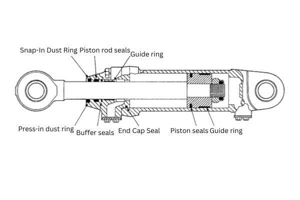
Positioning Within Hydraulic Cylinder Assemblies
Guide rings are strategically positioned within hydraulic cylinder assemblies to provide maximum support and guidance while minimizing interference with other components. In a typical double-acting hydraulic cylinder, guide rings are installed in two primary locations:
Piston guide rings: These are mounted on the outer diameter of the piston and guide its movement within the cylinder bore. Piston guide rings absorb side loads and maintain alignment between the piston and cylinder wall, preventing contact between these metal surfaces during operation. They are typically installed in grooves machined into the piston body.
Rod guide rings: These are positioned within the cylinder head or gland and guide the piston rod as it extends and retracts. Rod guide rings prevent the rod from contacting the cylinder head, absorb side loads, and maintain proper alignment between the rod and sealing components. Their positioning is critical for protecting rod seals from excessive wear and ensuring smooth operation.
The precise positioning and quantity of guide rings depend on factors such as cylinder size, operating pressure, expected side loads, and application requirements. In high-performance or heavy-duty applications, multiple guide rings may be employed at each location to distribute loads more effectively and provide redundancy in critical systems.
Distinction from Other Sealing Components
| Component | Primary Function | Sealing Capability | Load-Bearing/Guidance | Typical Material | Key Role in System |
| Guide Rings | Maintain alignment and absorb side loads | ❌ No | ✅ Yes | PTFE, composite materials | Prevent metal-to-metal contact; support piston and rod during movement |
| O-Rings | Prevent fluid leakage between mating surfaces | ✅ Yes | ❌ No | Elastomers (e.g., NBR, FKM) | Static or dynamic sealing in low-pressure applications |
| Piston Seals | Seal pressure chambers within the cylinder | ✅ Yes | ❌ No | Polyurethane, rubber, PTFE | Maintain pressure integrity during piston movement |
| Rod Seals | Prevent fluid leakage along the piston rod | ✅ Yes | ❌ No | Polyurethane, rubber | Seal the rod where it exits the cylinder; critical for external leakage control |
| Buffer Seals | Protect primary seals from pressure spikes/contaminants | ✅ Yes | ⚠️ Limited (some guidance) | PTFE, rubber composites | Act as secondary seals; reduce stress on main sealing elements in high-pressure zones |
The Split Design Concept
The split design in hydraulic cylinder guide rings refers to an intentional gap or opening in the ring’s circumference, creating a non-continuous circular component. This deliberate design feature, far from being a manufacturing limitation, represents a sophisticated engineering solution that addresses multiple challenges in hydraulic system operation, installation, and maintenance. The split design has become the industry standard for guide rings across various applications due to its numerous functional advantages over continuous ring alternatives.
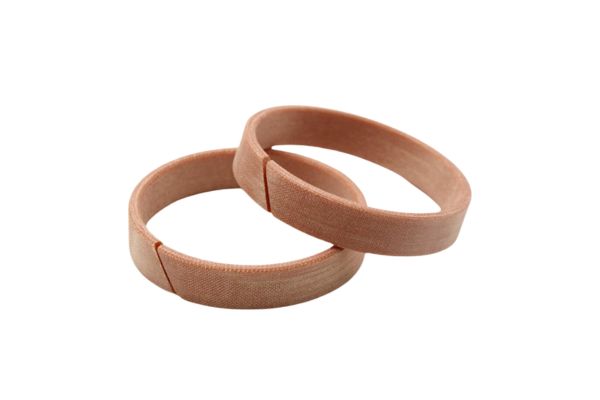
Defining Split Design Characteristics
A split design guide ring is characterized by a deliberate discontinuity in its circumference, creating an opening that allows the ring to be expanded or compressed during installation and operation. This opening, commonly referred to as a “cut” or “gap,” is precisely engineered in terms of its geometry, angle, and dimensions to optimize the ring’s performance under specific operating conditions. The presence of this gap transforms what would otherwise be a rigid circular component into a dynamic element capable of adapting to changing conditions within the hydraulic system.
The split in guide rings is not merely a simple cut but is engineered with specific profiles that enhance performance characteristics. The design of this split significantly influences the ring’s behavior during installation, operation, and under varying thermal conditions. The precision of this design element is critical to the overall functionality of the guide ring and, by extension, the hydraulic system it serves.
Types of Split Configurations
Hydraulic cylinder guide rings employ various split configurations, each designed to address specific operational requirements and performance characteristics:
- Straight Cut (Butt Cut) Design: The simplest form of split design features a straight cut perpendicular to the ring’s circumference. This configuration offers straightforward manufacturing and provides basic functionality for low to medium-pressure applications. Straight cut designs are characterized by their simplicity and cost-effectiveness but may offer less stability under high-pressure conditions or in applications with significant thermal fluctuations.
- Angled Cut Design: This configuration features a diagonal cut across the ring’s cross-section, typically at angles between 30 and 45 degrees. The angled cut provides improved sealing performance by reducing the direct path for fluid or pressure to traverse the gap. Additionally, this design distributes stress more effectively across the ring material, reducing the concentration of forces that could lead to premature wear or deformation. Angled cut guide rings are commonly employed in medium to high-pressure applications where enhanced stability and reduced gap extrusion are required.
- Step Joint Design: A more sophisticated approach, the step joint (also called lap joint) configuration incorporates an overlapping design where the ends of the ring interlock in a stepped pattern. This design significantly improves stability and reduces the potential for gap-related issues under high-pressure conditions. Step joint designs provide superior resistance to extrusion and offer enhanced guidance precision in demanding applications. The overlapping nature of this configuration also helps maintain consistent performance throughout thermal cycles and pressure fluctuations.
- Puzzle Cut Design: In specialized high-performance applications, guide rings may feature complex interlocking patterns resembling puzzle pieces. These sophisticated designs maximize contact area at the split while allowing necessary expansion and contraction. Puzzle cut configurations provide exceptional stability and resistance to deformation under extreme conditions but typically involve more complex manufacturing processes and higher production costs.
- Segmented Design: For very large diameter applications or specialized situations, guide rings may be manufactured as multiple segments rather than a single split ring. This approach facilitates installation in applications where traditional split rings would be impractical due to size constraints or installation limitations. Segmented designs require careful engineering to ensure proper alignment and performance across all segments.
The selection of an appropriate split configuration depends on various factors including operating pressure, temperature range, installation requirements, and expected service life. Engineers must carefully evaluate these considerations to determine the optimal design for specific applications.
Split vs. Non-Split Guide Rings
| Comparison Aspect | Split Guide Rings | Non-Split Guide Rings |
| Installation | Easy, no special tools required | Complex, may need tools or heating |
| Material Flexibility | Supports wide range, including high-performance composites | Limited to elastic materials |
| Thermal Adaptation | Compensates well for expansion/contraction | Prone to binding or looseness |
| Manufacturing Tolerance | More forgiving; gap allows dimensional variation | Requires very tight tolerances |
| Field Maintenance | Easy replacement with minimal disassembly | Often requires full disassembly |
| Performance Under Pressure | Predictable deformation, stable performance | Unpredictable deformation possible |
| Best For | Most standard/high-performance hydraulic applications | Niche or very small-diameter applications |
Thermal Expansion and Material Properties
The behavior of materials under varying temperature conditions represents a critical consideration in hydraulic system design. Hydraulic cylinders frequently operate across wide temperature ranges, from cold startup conditions to elevated temperatures during continuous operation. The split design of guide rings provides an elegant solution to the challenges posed by thermal expansion and contraction, ensuring consistent performance across diverse operating conditions.
Thermal Dynamics in Hydraulic Systems
Hydraulic systems generate heat through multiple mechanisms during operation:
- Fluid Friction: As hydraulic fluid flows through restrictions, orifices, and control valves, friction converts hydraulic energy into heat. This conversion is particularly significant in high-pressure systems or those operating at high flow rates.
- Mechanical Friction: The interaction between moving components—including pistons, rods, and sealing elements—generates frictional heat that transfers to surrounding components and the hydraulic fluid.
- Compression Heating: The compression of hydraulic fluid under pressure generates heat through adiabatic processes, particularly during rapid cycling or when operating at high pressures.
- Environmental Factors: External temperature conditions, solar radiation, and proximity to other heat-generating equipment can significantly influence the thermal environment of hydraulic systems.
These heat sources create temperature gradients and fluctuations that affect all system components, including guide rings. The resulting thermal expansion and contraction of materials present significant challenges for maintaining proper fit, function, and alignment within hydraulic cylinders.
Material Expansion Coefficients and Their Implications
Different materials expand and contract at varying rates when subjected to temperature changes, a property quantified by their coefficient of thermal expansion (CTE). This variation in expansion rates creates particular challenges in hydraulic systems where components made from different materials must maintain precise relationships despite temperature fluctuations:
- Polymer vs. Metal Expansion Rates: Guide rings are typically manufactured from polymer or composite materials with CTEs significantly higher than the metal components they interface with. For example, PTFE has a CTE approximately 10 times greater than steel, while phenolic composites may expand at 3-5 times the rate of their metal counterparts. This disparity means that as temperature increases, polymer guide rings naturally expand more rapidly than the metal cylinders and pistons they contact.
- Expansion Magnitude in Typical Applications: In a typical hydraulic application with an operating temperature range of 20°C to 80°C, a polymer guide ring might expand by 0.5-1.5% of its diameter, while the metal components expand by only 0.1-0.2%. This differential expansion would cause a continuous ring to either bind against surfaces at low temperatures or lose proper contact at high temperatures.
- Anisotropic Expansion in Composites: Many high-performance composite materials used in guide rings exhibit anisotropic thermal expansion, expanding at different rates in different directions due to their reinforcement structures. This complexity further complicates the thermal management of guide rings in hydraulic applications.
- Thermal Cycling Effects: Repeated heating and cooling cycles create additional challenges as components expand and contract repeatedly, potentially leading to fatigue, stress concentration, or dimensional instability in continuous ring designs.
How Split Designs Accommodate Thermal Expansion
The split design in guide rings provides an elegant solution to these thermal challenges by creating a controlled accommodation path for dimensional changes:
- Gap Compensation Mechanism: As temperature increases and the guide ring material expands, the split design allows this expansion to be accommodated through a reduction in the gap width rather than creating binding pressure against cylinder walls or piston surfaces. Conversely, as temperatures decrease and materials contract, the gap widens slightly while maintaining appropriate contact pressure on operational surfaces.
- Maintained Contact Pressure: Throughout thermal cycles, split designs maintain more consistent contact pressure against guiding surfaces than continuous alternatives. This consistency results from the natural spring-like behavior of the split ring, which continues to exert appropriate radial force despite dimensional changes.
- Prevention of Binding and Seizure: In continuous ring designs, thermal expansion can create excessive interference that leads to binding, increased friction, or even seizure of moving components. Split designs eliminate this risk by providing a controlled expansion path that prevents the development of excessive interference pressures.
- Accommodation of Differential Expansion: The split configuration effectively manages the differential expansion between polymer guide rings and metal components, maintaining appropriate clearances and contact patterns despite the significant differences in expansion rates.
- Stress Reduction During Thermal Cycling: By accommodating dimensional changes through the gap rather than creating internal stress, split designs reduce material fatigue and extend service life in applications subject to frequent thermal cycling.
Preload Force Optimization
The concept of preload force represents a critical but often overlooked aspect of hydraulic cylinder guide ring functionality. Preload refers to the radial force that a guide ring exerts against the cylinder bore or piston rod during operation. This force must be carefully balanced—sufficient to maintain proper alignment and prevent metal-to-metal contact, yet not so excessive as to create unnecessary friction or accelerated wear. The split design of guide rings provides a sophisticated mechanism for optimizing this preload force across various operating conditions.
Concept of Preload Force in Guide Rings
Preload force in guide rings serves several essential functions within hydraulic systems:
- Contact Maintenance: The primary purpose of preload is to ensure continuous contact between the guide ring and the mating surface (cylinder bore or rod) throughout the stroke cycle. This continuous contact is essential for maintaining alignment and preventing metal-to-metal contact between moving components.
- Clearance Control: Appropriate preload helps maintain optimal clearances between moving components, preventing excessive play that could lead to misalignment while avoiding interference that would increase friction and wear.
- Load Distribution: Preload force distributes side loads across the guide ring surface area, reducing pressure concentrations that could lead to accelerated wear or deformation of both the guide ring and mating surfaces.
- Vibration Damping: Proper preload provides damping against vibrations and shock loads that might otherwise cause component damage or accelerated wear in hydraulic systems operating in dynamic environments.
- Sealing Support: While not primary sealing elements themselves, guide rings with appropriate preload help maintain the alignment necessary for adjacent sealing components to function effectively, indirectly supporting system sealing integrity.
The optimization of preload force represents a delicate balance between competing requirements. Insufficient preload may allow misalignment or metal-to-metal contact, while excessive preload increases friction, accelerates wear, and reduces energy efficiency. This balance becomes particularly challenging given the variable operating conditions most hydraulic systems encounter.
How Split Designs Create Optimal Radial Pressure
Split design guide rings provide a sophisticated mechanism for generating and maintaining appropriate preload force:
- Inherent Spring Effect: The split configuration creates an inherent spring-like behavior in the guide ring. When compressed during installation into a groove or cylinder bore smaller than the ring’s free diameter, the split design stores potential energy that generates a consistent outward radial force. This mechanical principle allows the ring to maintain contact pressure despite variations in operating conditions.
- Controlled Interference Fit: Split designs enable the creation of a precise interference fit between the guide ring and its housing. The gap in the ring closes partially during installation, creating a predetermined amount of compression that translates directly into radial preload force. This interference can be precisely engineered during manufacturing to achieve optimal preload for specific applications.
- Dynamic Adaptation: Unlike continuous rings that provide relatively fixed preload based solely on material elasticity, split designs offer dynamic adaptation to changing conditions. The gap can open or close slightly in response to pressure fluctuations, thermal expansion, or wear, maintaining more consistent preload throughout the service life.
- Stress Distribution: The split configuration distributes installation and operational stresses more evenly throughout the ring material, preventing stress concentrations that could lead to premature failure. This distribution allows for higher overall preload without exceeding material limitations at any specific point.
- Controlled Deformation Path: The split provides a predetermined path for material deformation under load, ensuring that compression forces result in predictable and beneficial preload rather than unpredictable distortion that might occur in continuous rings.
Prevention of “Cocking” or Misalignment
One of the most significant benefits of optimized preload in split design guide rings is the prevention of “cocking” or misalignment during cylinder operation:
- Consistent Radial Support: The uniform preload provided by split designs ensures consistent radial support around the circumference of the piston or rod, preventing the development of uneven forces that could cause tilting or cocking of moving components.
- Immediate Response to Side Loads: When side loads are applied to a hydraulic cylinder—as frequently occurs in real-world applications—the optimized preload of split design guide rings ensures immediate response and support, preventing momentary misalignment that could damage sealing surfaces or initiate wear patterns.
- Elimination of Stick-Slip Behavior: Properly optimized preload in split designs helps eliminate stick-slip behavior that can occur when components momentarily bind and then release during operation. This smooth operation prevents the jerky motion that can lead to misalignment and accelerated wear.
- Compensation for Wear: As components wear during normal operation, the spring-like behavior of split design guide rings continues to provide appropriate preload, maintaining alignment even as dimensional relationships gradually change. This compensation significantly extends the service interval for hydraulic systems.
- Resistance to Shock Loading: The optimized preload of split designs provides resistance to shock loading that might otherwise cause momentary misalignment or component damage. This resistance is particularly valuable in mobile equipment or applications subject to variable or unpredictable loading.
Manufacturing Tolerance Compensation
In the precision-driven world of hydraulic systems, manufacturing tolerances represent a significant challenge for component designers and system engineers. Even with advanced manufacturing techniques, dimensional variations are inevitable in both guide rings and the metal components they interface with. The split design of hydraulic cylinder guide rings provides an elegant solution to these tolerance challenges, offering inherent compensation capabilities that enhance system reliability and performance.
Challenges of Manufacturing Precision in Hydraulic Components
The production of hydraulic cylinders and their components involves numerous precision challenges:
- Dimensional Variations: Despite advanced manufacturing processes, metal components such as cylinder bores, pistons, and rods inevitably exhibit dimensional variations. These variations may be within acceptable tolerance ranges but still create challenges for achieving optimal fit and function with guide rings.
- Geometric Imperfections: Beyond simple dimensional variations, components may exhibit geometric imperfections such as out-of-roundness, taper, or surface irregularities that affect the interface with guide rings. These imperfections can be particularly challenging to address with continuous ring designs that lack adaptive capabilities.
- Cumulative Tolerance Stacking: In assembled systems, the individual tolerances of multiple components combine to create cumulative variations that exceed the tolerance of any single component. This tolerance stacking effect amplifies the challenge of achieving consistent performance across production units.
- Material-Specific Manufacturing Limitations: Different materials used in hydraulic systems present unique manufacturing challenges. For example, the machining characteristics of bronze differ significantly from those of steel or aluminum, resulting in different achievable tolerance ranges for components made from these materials.
- Cost-Precision Balance: While tighter manufacturing tolerances are technically possible, they exponentially increase production costs. Practical hydraulic system design requires balancing precision requirements against economic constraints, often necessitating components that can accommodate reasonable tolerance variations.
- Post-Manufacturing Deformation: Processes such as heat treatment, plating, or surface hardening can cause minor deformation in metal components after initial machining. These secondary effects are difficult to predict precisely and create additional dimensional variability.
These manufacturing realities create significant challenges for guide ring design, particularly when considering the need for consistent performance across thousands of production units and throughout the service life of hydraulic equipment.
How Split Designs Accommodate Dimensional Variations
Split design guide rings offer remarkable capabilities for accommodating the dimensional variations inherent in manufactured components:
- Gap-Based Compensation: The fundamental advantage of split designs lies in their ability to expand or contract via the gap to accommodate dimensional variations in mating components. A guide ring with a properly designed split can adapt to cylinder bores or rod diameters that vary within a specified tolerance range while maintaining appropriate preload force.
- Self-Adjusting Installation: During installation, split design guide rings naturally adjust to the actual dimensions of the components they contact rather than relying on theoretical nominal dimensions. This self-adjustment ensures optimal fit regardless of where within the tolerance range a particular component falls.
- Consistent Preload Across Tolerance Range: While continuous rings would provide significantly different preload forces depending on the exact dimensions of mating components, split designs maintain more consistent preload across the tolerance range. This consistency results from the spring-like behavior created by the split configuration.
- Accommodation of Geometric Imperfections: Beyond simple dimensional variations, split designs can conform to minor geometric imperfections such as out-of-roundness or taper. This conformability ensures more consistent contact and performance than would be possible with rigid continuous rings.
- Dynamic Adaptation: Throughout the service life of hydraulic equipment, components may undergo minor dimensional changes due to wear, thermal cycling, or material relaxation. Split design guide rings continue to provide appropriate fit and function despite these gradual changes, extending effective service life.
- Installation Stress Reduction: Components manufactured at opposite ends of their tolerance ranges can create significant installation stress for continuous rings. Split designs dramatically reduce this stress by accommodating dimensional variations through the gap, preventing damage during assembly.
Conclusion
Understanding why hydraulic cylinder guide rings use split designs provides valuable insight not only into these specific components but also into the broader principles of effective engineering solutions, where elegance often lies in finding the simplest approach that comprehensively addresses complex requirements.
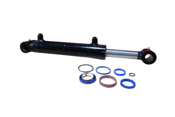
If you still want to order hydraulic cylinders, contact Topa and we will provide you with the best service.
FAQ
What is the primary function of a guide ring in a hydraulic cylinder?
Guide rings maintain alignment between the piston and cylinder components, preventing metal-to-metal contact and absorbing lateral (side) loads during operation.
Do guide rings provide sealing like O-rings or piston seals?
No. Guide rings are not sealing elements—they are structural components that provide guidance and support. Sealing is handled by separate elements like piston and rod seals.
Why do most guide rings use a split design?
Split designs simplify installation, allow the use of stronger composite materials, accommodate thermal expansion, and reduce maintenance complexity—making them ideal for most hydraulic applications.
Can split guide rings be replaced without removing the entire hydraulic cylinder?
In many cases, yes. Split guide rings can often be replaced in the field with minimal disassembly, saving time and reducing downtime.
What materials are commonly used for guide rings?
Typical materials include PTFE (polytetrafluoroethylene), filled nylon, and fiber-reinforced composites—chosen for their wear resistance and load-bearing capacity.
How do I choose the right guide ring for my application?
Consider factors such as operating pressure, temperature range, load conditions, and compatibility with hydraulic fluids. Also, ensure the guide ring fits correctly within the housing dimensions and system tolerances.