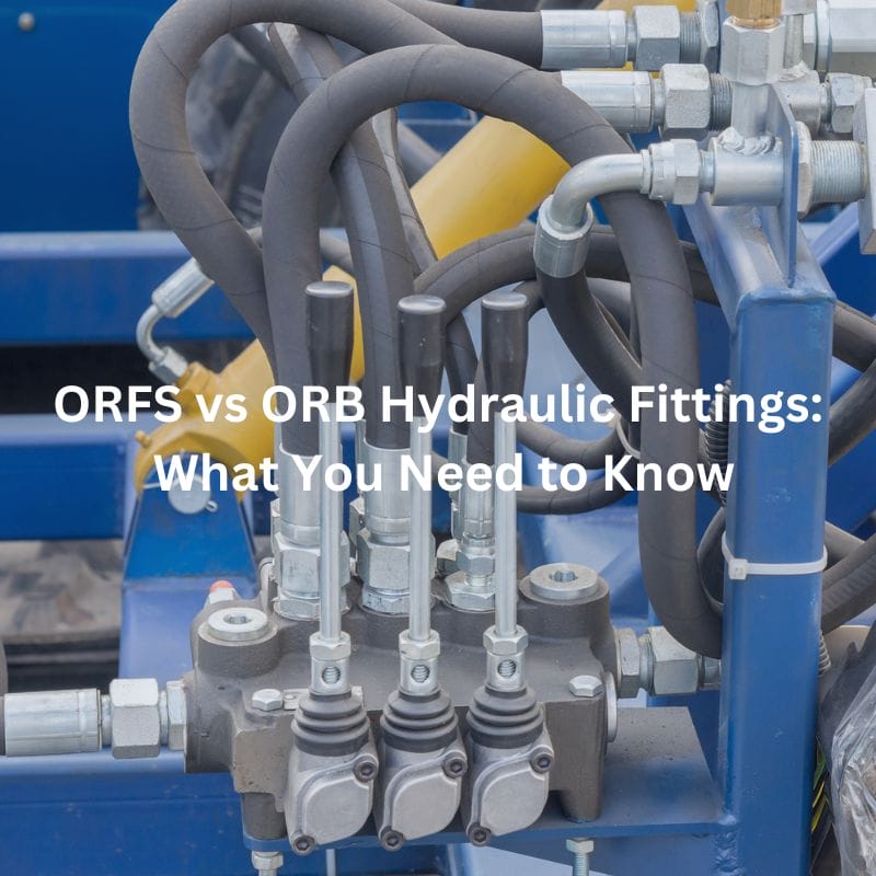
ORFS vs ORB Hydraulic Fittings: What You Need to Know
Table of Contents
Introduction
Choosing the right hydraulic fittings is crucial for ensuring the efficiency and reliability of hydraulic systems. This comprehensive guide delves into the differences between ORFS (O-Ring Face Seal) and ORB (O-Ring Boss) hydraulic fittings, offering insights into their design, functionality, advantages, and applications. Understanding these differences will help you make informed decisions for your hydraulic systems.
What are ORFS Hydraulic Fittings?
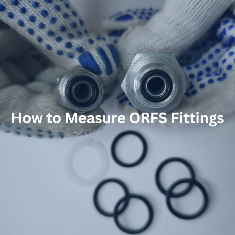
ORFS (O-Ring Face Seal) hydraulic fittings are engineered to provide a highly secure and leak-free connection within hydraulic systems. These fittings are characterized by their use of an O-ring seated in a groove on the fitting’s face, which, when compressed against a flat surface, creates an effective seal. The design of ORFS fittings makes them particularly suitable for high-pressure applications and environments where preventing leaks is critical.
Components and Design of ORFS Hydraulic Fittings
The ORFS fittings are composed of three primary components:
Body: The main structure of the fitting, is a flat face with a groove designed to hold the O-ring. This flat face ensures that when the fitting is assembled, the O-ring is compressed uniformly to create a reliable seal.
O-Ring: A rubber or elastomeric ring seated in the groove on the face of the fitting. The O-ring is the critical sealing element, designed to compress and deform slightly to fill any gaps between the fitting and the mating surface, thereby preventing leaks. The material of the O-ring is chosen based on the fluid type and operating temperature of the system to ensure compatibility and longevity.

Functionality of ORFS Hydraulic Fittings
ORFS fittings operate based on a simple yet highly effective sealing mechanism. Here is a step-by-step breakdown of their functionality:
Preparation: Before installation, the fitting and the mating surface should be clean and free of debris. The O-ring should be inspected for any signs of damage or wear.
Assembly: The fitting body is aligned with the mating surface, and the nut is threaded onto the corresponding male thread. As the nut is tightened using a wrench, it drives the flat face of the fitting body towards the mating surface.
Sealing: As the fitting body is drawn closer, the O-ring seated in the groove on the face of the fitting begins to compress. The flat face of the fitting ensures even compression of the O-ring against the flat mating surface. This compression deforms the O-ring slightly, creating a robust seal that can withstand high pressures.
Operation: Once installed, the ORFS fitting provides a secure and leak-free connection. The O-ring’s elasticity allows it to maintain the seal even under varying pressures and temperatures, making ORFS fittings highly reliable in demanding environments.
Advantages of ORFS Hydraulic Fittings
Leak Prevention: The primary advantage of ORFS fittings is their ability to prevent leaks. The O-ring face seal design ensures that the connection remains secure and leak-free, even under high pressure.
Durability: ORFS fittings are designed to withstand harsh conditions, including high pressure, vibration, and thermal cycling. This makes them suitable for both industrial and mobile hydraulic systems.
Ease of Installation: The design of ORFS fittings allows for easy installation with standard wrenches, reducing the need for specialized tools and training.
High-Pressure Capability: ORFS fittings can handle high-pressure applications, often up to 6,000 psi, depending on the size and material. This makes them ideal for applications where high performance and reliability are essential.
Applications of ORFS Hydraulic Fittings
ORFS hydraulic fittings are widely used across various industries due to their reliability and performance in high-pressure environments. Some common applications include:
Industrial Machinery: In manufacturing plants and industrial machinery, ORFS fittings are used to connect hydraulic lines that power equipment such as presses, injection molding machines, and conveyors.
Mobile Equipment: Heavy machinery like excavators, loaders, and bulldozers rely on ORFS fittings for their hydraulic systems to ensure leak-free operation in rugged conditions.
Aerospace: In the aerospace industry, ORFS fittings are used in hydraulic systems that require high reliability and performance, such as landing gear and flight control systems.
Automotive: High-performance vehicles and heavy-duty trucks use ORFS fittings in their hydraulic systems for brakes, power steering, and suspension.
What are ORB Hydraulic Fittings?
ORB (O-Ring Boss) fittings are hydraulic fittings designed to create a secure seal using an O-ring placed in a groove on the fitting’s boss (a cylindrical extension). When the fitting is tightened, the O-ring is compressed between the boss and the mating surface, creating a reliable seal. ORB fittings are commonly used in applications requiring high pressure and where space is limited, offering a compact and efficient solution.

Components and Design
ORB fittings consist of several key components:
Body: The main component of the ORB fitting, featuring a threaded boss and a groove for the O-ring. The body is typically made of durable materials such as steel, stainless steel, or brass, ensuring the fitting can withstand high pressures and harsh environments.
O-Ring: An elastomeric ring that fits into the groove on the boss. The O-ring is crucial for creating the seal, and its material is selected based on the type of hydraulic fluid and the operating conditions (e.g., temperature, pressure).
Threaded Boss: A cylindrical extension with external threads, allowing the fitting to be screwed into a corresponding female port. The boss also includes a groove for the O-ring, which is compressed to form the seal.
Hex Nut: In some ORB fittings, a hex nut is included to facilitate the tightening of the fitting. This component ensures that the fitting can be securely fastened, providing the necessary compression for the O-ring to seal effectively.
Functionality
ORB fittings operate by creating a seal through the compression of the O-ring. Here’s a step-by-step explanation of their functionality:
Preparation: Before installation, ensure the fitting and the female port are clean and free of debris. Inspect the O-ring for any signs of damage or wear.
Insertion: Insert the ORB fitting’s threaded boss into the corresponding female port. Align the fitting so that the O-ring is positioned correctly within the groove on the boss.
Tightening: Using a wrench, tighten the fitting by turning the hex nut or the body of the fitting. As the fitting is tightened, the threaded boss is drawn into the female port, and the O-ring begins to compress.
Sealing: The compression of the O-ring between the boss and the mating surface creates a secure seal. The elastomeric material of the O-ring deforms slightly to fill any gaps, ensuring a leak-proof connection.
Operation: Once installed, ORB fittings provide a reliable and leak-free connection. The O-ring maintains its seal under varying pressures and temperatures, making ORB fittings suitable for high-pressure hydraulic systems.
Applications of ORB Hydraulic Fittings
ORB fittings are versatile and used in various hydraulic applications, including:
Hydraulic Cylinders: ORB fittings are commonly used in hydraulic cylinders, where space is limited, and a reliable seal is essential for maintaining pressure and preventing leaks.
Pumps and Motors: Hydraulic pumps and motors often use ORB fittings to connect hoses and tubes, ensuring a secure and efficient transfer of hydraulic fluid.
Industrial Equipment: In industrial machinery, ORB fittings provide compact and reliable connections in systems that operate under high pressure and require precise fluid control.
Mobile Hydraulic Systems: ORB fittings are used in mobile hydraulic systems found in construction and agricultural equipment, where their compact design and high-pressure capabilities are beneficial.
Key Differences Between ORFS and ORB Hydraulic Fittings
Design and Structure
ORFS (O-Ring Face Seal) Fittings:
Flat Face Design: ORFS fittings have a flat face with a groove designed to hold an O-ring. This design ensures that when the fitting is tightened, the O-ring is compressed against a flat mating surface.
Components: The main components of ORFS fittings include the fitting body, a nut, and an O-ring. The flat face and the O-ring groove are integral to its design, providing a smooth sealing surface.
Thread Type: ORFS fittings typically have straight threads which are used to bring the faces together without sealing. The sealing is achieved through the O-ring compression on the flat face.
ORB (O-Ring Boss) Fittings:
Threaded Boss Design: ORB fittings feature a cylindrical boss with external threads and a groove for the O-ring. The boss is threaded, allowing it to be screwed into a corresponding female port.
Components: ORB fittings consist of a threaded boss, an O-ring, and in some designs, a hex nut to facilitate tightening. The O-ring sits in a groove on the boss, which is key to its sealing function.
Thread Type: ORB fittings use straight threads as well, but these threads are part of the boss that screws into the female port. The sealing occurs between the O-ring and the port surface.
Sealing Mechanism
ORFS Fittings:
Face Seal: The primary sealing mechanism in ORFS fittings is the compression of the O-ring against the flat face of the fitting. When the fitting is tightened, the O-ring is compressed between the flat face and the mating surface, creating a robust seal.
Implications: This design minimizes the risk of leaks and is highly effective in high-pressure environments. The flat face ensures even compression of the O-ring, enhancing the seal’s reliability.
ORB Fittings:
Boss Seal: ORB fittings seal by compressing the O-ring between the threaded boss and the mating surface inside the female port. The O-ring fits into a groove on the boss and is compressed when the fitting is tightened.
Implications: The boss seal mechanism allows for a compact design, making ORB fittings suitable for applications with space constraints. However, precise alignment during installation is crucial to ensure an effective seal.

Pressure Ratings
ORFS Fittings:
High Pressure: ORFS fittings are designed to handle very high pressures, often up to 6,000 psi, depending on the size and material. The flat face seal with the O-ring provides a robust sealing mechanism capable of withstanding extreme pressures.
Reliability: The reliability of the seal in ORFS fittings makes them ideal for critical applications where leaks cannot be tolerated.
ORB Fittings:
Moderate to High Pressure: ORB fittings are also capable of handling high pressures, though typically slightly lower than ORFS fittings, with ratings generally up to 5,000 psi. The threaded boss design provides a strong and secure connection suitable for high-pressure systems.
Versatility: While they can handle high pressures, ORB fittings are versatile and can be used in a variety of applications, making them a popular choice in many hydraulic systems.
Choosing the Right Fitting for Your Needs
Selecting the appropriate hydraulic fitting for your system is crucial for ensuring optimal performance, reliability, and safety. When deciding between ORFS and ORB fittings, several key factors and application-specific requirements must be considered.
Factors to Consider
Sealing Performance:
Sealing performance is vital in preventing leaks and maintaining system integrity. ORFS fittings excel in this area due to their flat face design, which ensures uniform compression of the O-ring and creates a highly reliable seal. ORB fittings, while effective, rely on the O-ring being compressed between the boss and the mating surface, which can require more precise installation to achieve a perfect seal.
Material Compatibility:
The materials used for the fittings and their compatibility with the hydraulic fluid and operating environment are critical. Both ORFS and ORB fittings are available in various materials such as steel, stainless steel, and brass. It is essential to select a fitting material that is compatible with the hydraulic fluid to prevent corrosion and ensure long-term reliability.
Cost Considerations:
Cost is always a factor in selecting hydraulic fittings. ORFS fittings tend to be more expensive due to their advanced sealing design and high-pressure capabilities. However, the investment can be justified by their superior performance in leak prevention and high-pressure environments. ORB fittings, while generally less expensive, offer reliable performance and are a cost-effective choice for many high-pressure applications where space efficiency is also a concern.
Conclusion
Understanding the differences between ORFS and ORB hydraulic fittings is crucial for selecting the right components for your hydraulic systems. Considering factors like pressure requirements, sealing performance, space constraints, ease of installation, material compatibility, and cost will help you make informed decisions. This, in turn, enhances the efficiency and reliability of your hydraulic systems, ensuring optimal performance in various applications.
FAQ
What does ORFS stand for?
ORFS stands for O-Ring Face Seal. These fittings use an O-ring compressed against a flat face to create a secure, leak-free seal.
What does ORB stand for?
ORB stands for O-Ring Boss. These fittings seal by compressing an O-ring between a threaded boss and the mating surface.
In which industries are ORFS fittings commonly used?
ORFS fittings are commonly used in industrial machinery, mobile equipment, and aerospace applications due to their high-pressure capabilities and reliable sealing performance.
Which fitting is more compact?
ORB fittings are more compact due to their threaded boss design, making them ideal for applications with limited space.
Are ORFS fittings easier to install than ORB fittings?
Yes, ORFS fittings are typically easier to install because their flat face design requires less precise alignment compared to ORB fittings.
Which fitting type handles higher pressure?
ORFS fittings generally handle higher pressures, up to 6,000 psi, making them suitable for extremely high-pressure applications.


