How to Measure SAE Fitting

How to Measure SAE Fitting

How to Measure SAE Fitting: Step-by-Step Guide

Introduction

There are several types of SAE fittings, including SAE J512, which is commonly used in automotive and refrigeration systems, and SAE J514, which is commonly used in hydraulics. each type has specific characteristics and applications. The purpose of this guide is to provide a comprehensive, step-by-step approach to accurately measuring SAE fittings. Accurate measurements are critical to ensure proper fitting selection, compatibility, and system integrity, ultimately improving the efficiency and longevity of your hydraulic system.

Understanding SAE Fittings

Definition and Characteristics of SAE Fittings

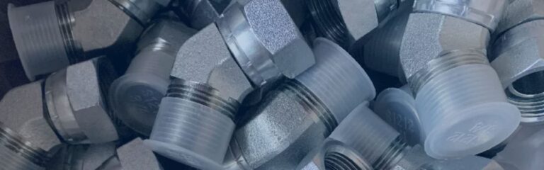
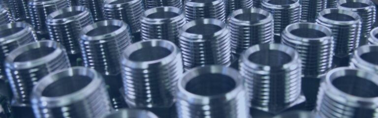
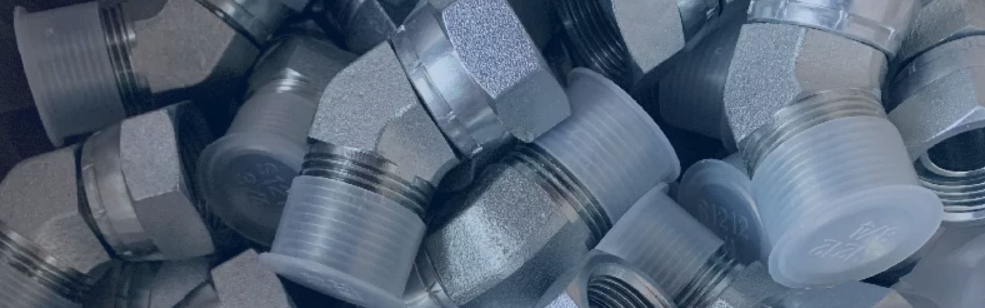
SAE fittings are standardized connectors established by the Society of Automotive Engineers. SAE fittings are characterized by their precision engineering, which allows them to maintain high performance under varying pressures and temperatures. They are made from robust materials like stainless steel, carbon steel, and brass, which provide durability and resistance to corrosion. The key characteristics of SAE fittings include their specific thread types, sealing methods, and dimensional standards, which ensure compatibility and interchangeability across different hydraulic systems and components.

SAE J512

SAE J512 fittings are widely used in the automotive and refrigeration industries. These fittings are designed for low and medium-pressure applications and are available in flared and inverted flared connection designs. In automotive systems, SAE J512 fittings are used in fuel lines, brake lines, and drivelines to provide secure, leak-proof connections. In refrigeration systems, these fittings are essential for connecting various components such as compressors, evaporators, and condensers to ensure efficient and reliable operation.

SAE J514

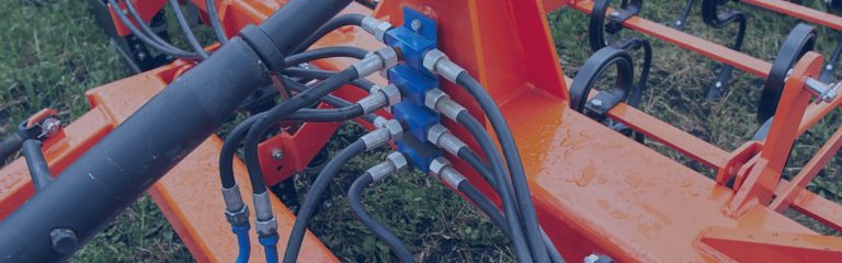
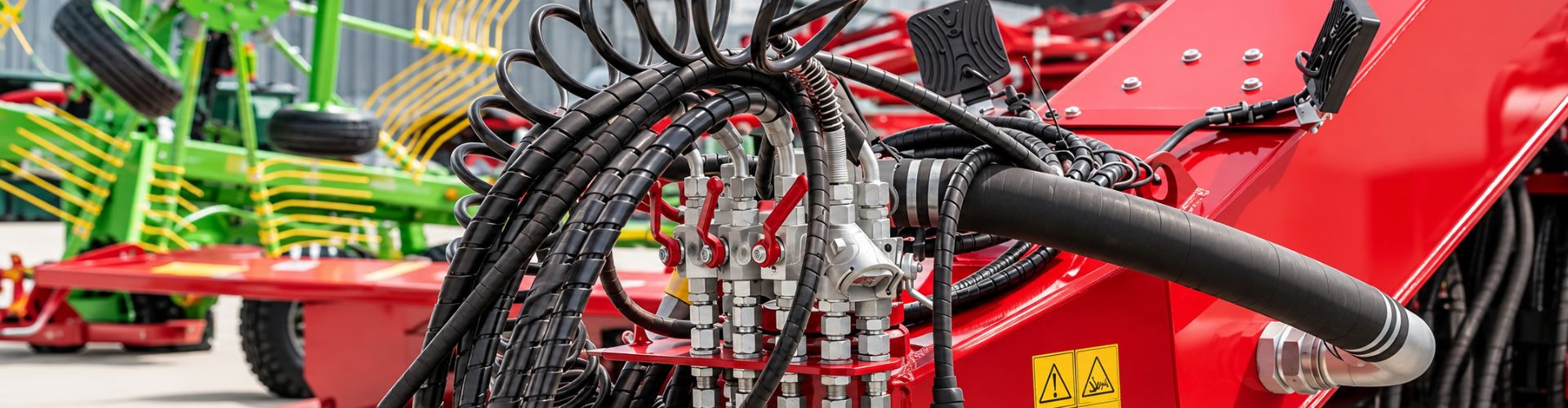
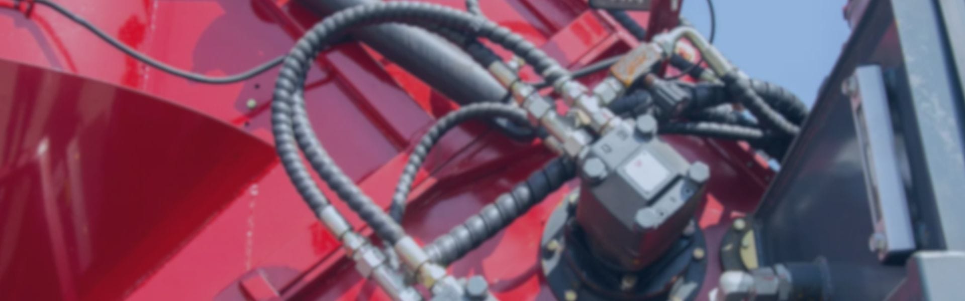
SAE J514 fittings are primarily used in hydraulic systems because of their ability to withstand high-pressure environments. These fittings include a variety of connection types, such as straight thread, tapered thread, and four-bolt flange connections. sae j514 fittings are critical in heavy machinery, industrial equipment, and mobile hydraulic applications to ensure the safe and efficient delivery of hydraulic fluid. The design of these fittings includes metal-to-metal or elastomeric seals that provide a reliable barrier against leakage. SAE J514 fittings are ruggedly constructed and precision threaded for demanding hydraulic applications to ensure system life and performance.

SAE J1453

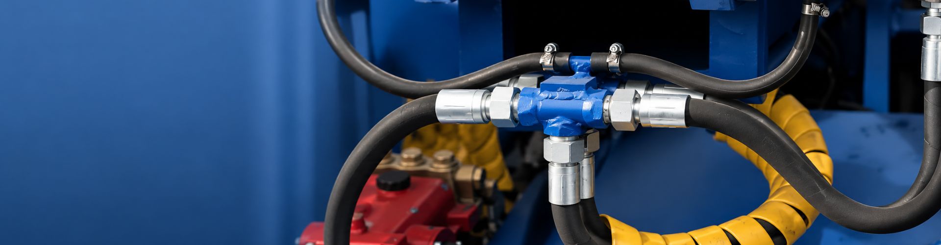
SAE J1453, commonly known as O-Ring Face Seal (ORFS) fittings, are designed for high-pressure hydraulic applications where leak prevention is critical. ORFS fittings feature a flat face and an O-ring seal, which provides a superior seal compared to traditional metal-to-metal contact. This design significantly reduces the risk of leaks, even under high-pressure conditions, making ORFS fittings ideal for use in hydraulic systems exposed to extreme pressures and vibrations. Applications for SAE J1453 fittings include heavy construction equipment, agricultural machinery, and industrial hydraulic systems. The O-ring seal ensures a tight connection, minimizing downtime and maintenance costs associated with hydraulic fluid leaks.

Differences Between SAE Fittings and Other Standard Fittings

JIC vs SAE

NPT Hydraulic Fittings

NPT fittings, standardized under ANSI/ASME B1.20.1, utilize tapered threads to create a seal as they are screwed together, often requiring thread sealant to enhance the seal. Commonly used in plumbing, gas lines, and low-pressure fluid transfer applications, NPT fittings are known for their simple design and ease of use in low to medium-pressure environments. Unlike SAE fittings, which use straight threads and various sealing mechanisms like O-rings, NPT fittings rely on thread interference for sealing, making them distinct in design and function.

BSP Fittings

BSP fittings, standardized under BS 21 and ISO 228, come in two thread types: BSPT (tapered) and BSPP (parallel). These fittings are commonly used in plumbing and hydraulic systems, particularly in Europe and other regions. BSPT fittings create a seal using thread taper, while BSPP fittings require a washer or O-ring for sealing. With a 55° thread angle, BSP threads differ from SAE threads, which have a 60° angle. Additionally, BSP threads include both tapered (BSPT) and parallel (BSPP) designs, whereas SAE fittings typically use straight threads. BSP fittings are widely used internationally and are versatile for various applications.

Metric Fittings

Metric fittings, standardized under ISO 261 and ISO 262, use metric threads (M) measured in millimeters for pitch and diameter. Commonly applied in international hydraulic systems, automotive, and machinery, these fittings often utilize O-rings or bonded seals for sealing. The metric system’s ease of integration and international standardization offer significant advantages. Unlike SAE fittings, which use inches for thread measurement, metric fittings rely on millimeters. Additionally, while metric fittings share some sealing methods with SAE fittings, such as O-rings, they differ from NPT and BSPT fittings, which use thread interference for sealing.

Feature

SAE

JIC

NPT

BSP

Metric

Thread Type

UN/UNF

UN/UNF

Tapered
(NPT)

Tapered(BSPT),
Parallel (BSPP)

Metric(M)

Common
Applications

Automotive,
hydraulic
Systems,
refrigeration,
aerospace

Hydraulic
systems,
fuel
delivery
fluid power

Plumbing,
gas  lines,
low-
pressure
fluid
transfer

Plumbing,
hydraulic
systems in
Europe

International
hydraulic
systems,
automotive,
machinery

Sealing
Method

Metal-to-
metal,O-rings

37°flare
metal-to-
metal

Tapered
threads
with sealant

Tapered
threads,
washers,O-
rings

O-rings,
bonded seals

Thread
Angle

60°

37°flare

60°

55°

Varies

Advantages

High reliability,
precision,
vibration
resistance

High

pressure
and
vibration
resistance

Simple,
easy to use

Widely used
internationally,
versatile

International
standard,easy
integration

Step-by-Step Guide

Outer Diameter of the Fitting

Tools Needed:

Calipers (digital or vernier)

Clean cloth or brush

Steps:

Clean the Fitting: Before measuring, ensure that the fitting is clean and free from any debris or corrosion. Use a clean cloth or brush to remove any dirt or residues that might affect the measurement.

Zero the Calipers: If using digital calipers, ensure they are zeroed before measuring. For vernier calipers, ensure they are correctly set to zero.

Position the Calipers: Open the calipers and place them around the outermost part of the fitting’s diameter. Ensure the calipers are perpendicular to the fitting to avoid angled measurements, which can result in inaccuracies.

Measure the Diameter: Gently close the calipers until they touch the fitting’s surface without compressing it. Read the measurement displayed on the digital calipers or from the vernier scale. Record the outer diameter.

Verify the Measurement: Repeat the measurement process a few times to ensure consistency. If the measurements vary, average them to get a reliable diameter.

hydraulic fittings measure tools Topa

Length of the Fitting

Tools Needed:

Measuring tape or ruler

Calipers (for smaller fittings)

Steps:

Prepare the Fitting: As with the diameter measurement, ensure the fitting is clean and free from debris.

Select the Measuring Tool: Use a measuring tape for larger fittings or calipers for smaller fittings.

Measure the Length: Place the measuring tool along the length of the fitting, starting from one end to the other. Ensure the measuring tape or ruler is straight and not bent, as this can lead to inaccuracies.

Record the Measurement: Note the length indicated on the measuring tool. For smaller fittings, use calipers for a more precise measurement by placing the jaws at the two ends of the fitting.

Repeat for Accuracy: Measure the length multiple times to ensure accuracy and record the most consistent measurement.

Flare Angle Measurement (If Applicable)

Tools Needed:

Flare gauge or protractor

Calipers (for measuring reference points)

Steps:

Identify the Flare Angle: Determine if the fitting has a flare angle. Common flare angles are 37° (AN/JIC fittings) and 45° (SAE fittings).

Use a Flare Gauge: Place the flare gauge against the fitting’s flare to check the angle. Ensure the gauge is properly aligned with the flare surface.

Measure with a Protractor: If a flare gauge is not available, use a protractor. Place the fitting on a flat surface and align the protractor’s center with the fitting’s center. Measure the angle by aligning the protractor’s baseline with the fitting’s flare surface.

Record the Angle: Note the flare angle measured. Verify the angle by measuring at different points around the flare to ensure uniformity.

Confirm Accuracy: Double-check the flare angle by comparing it with standard flare angles for SAE fittings to confirm it matches the expected angle.

Examine the Threads

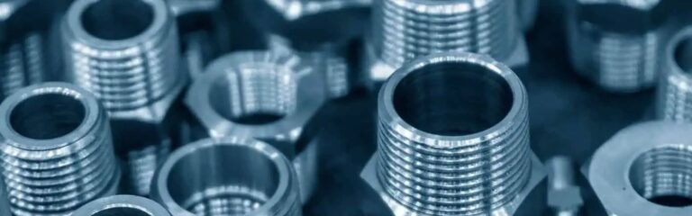
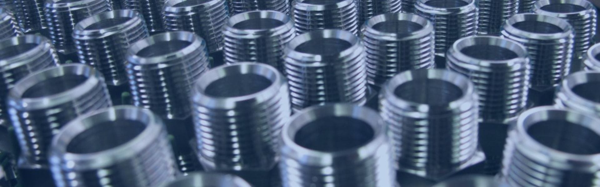
Once cleaned, closely examine the threads to identify the type of thread. SAE fittings typically use UN (Unified National) or UNF (Unified National Fine) threads. The type of thread can often be determined by the appearance and feel of the threads, but for precise identification, you may refer to thread charts or standards.

Unified National Fine (UNF)

UNF threads have a finer pitch, meaning the threads are closer together compared to UNC threads. This results in more threads per inch (TPI). UNF threads are available across a range of diameters, typically from small to medium sizes. The finer threads provide a greater surface area in contact with the mating part, which can offer a stronger and more secure hold.

Unified National Coarse (UNC)

UNC threads have a coarser pitch, meaning the threads are spaced further apart compared to UNF threads. This results in fewer threads per inch (TPI). UNC threads are also available in a wide range of diameters, typically from small to large sizes. The coarser threads make UNC fasteners easier to assemble and disassemble, even in less-than-ideal conditions.

Thread Pitch Measurement

Select the Thread Gauge

Thread pitch gauges come with multiple blades, each marked with different pitch values. Select a thread pitch gauge that corresponds to the type of threads you are measuring (UN or UNF). Ensure that the gauge covers the range of thread pitches you might encounter in SAE fittings.

Match the Threads

Take the thread pitch gauge and place one of its blades against the threads of the fitting. Ensure that the blade is aligned with the threads, making full contact along the entire length of the threads.

Slide the blade gently along the threads to see if it matches perfectly. If it does not, try the next blade on the gauge until you find one that fits precisely. The correct blade will nestle perfectly into the threads without any gaps or rocking.

Confirm the Match: A perfect match means that the blade’s teeth align exactly with the thread grooves on the fitting. The gauge should fit snugly into the threads without forcing it.

Read the Pitch

Once you find the blade that matches the threads, look at the markings on the thread pitch gauge. The blade will have a pitch value indicated, usually in threads per inch (TPI) for SAE threads.

Note the pitch value. This value represents the number of threads per inch and is critical for ensuring you have the correct thread specifications for replacement or compatibility checks.

Identifying Thread Types and Sizes

Accurately identifying thread types and sizes is essential for ensuring proper fit and function in hydraulic systems. SAE (Society of Automotive Engineers) fittings commonly use Unified National (UN) and Unified National Fine (UNF) thread types. This section explains these thread types and provides a detailed guide on how to identify thread type and size using thread gauges, understanding thread pitch, and determining thread diameter.

Troubleshooting Common Issues

Accurately measuring SAE fittings is crucial for ensuring the proper fit and function of hydraulic systems. However, several common problems can arise during the measurement process. This section highlights these issues and provides solutions and tips for troubleshooting them.

Incorrect Thread Identification

Issue:

Misidentifying thread type (e.g., UNC vs. UNF) can lead to selecting the wrong fitting, causing leaks or mechanical failures.

Solution:

Clean the Threads: Ensure threads are clean before measuring. Debris can obscure the thread profile.

Use Correct Gauges: Use thread pitch gauges specifically designed for SAE threads. Verify the pitch using multiple gauges if necessary.

Consult Standards: Cross-reference your measurements with standard thread charts to confirm the thread type.

Inaccurate Measurements Due to Tool Errors

Issue:

Calipers, micrometers, and thread gauges can give inaccurate readings if they are not calibrated or used correctly.

Solution:

Calibrate Regularly: Ensure all measurement tools are regularly calibrated according to manufacturer specifications.

Use Quality Tools: Invest in high-quality measuring tools to minimize errors. Cheap tools can be prone to inaccuracies and wear out quickly.

Check Tool Condition: Inspect tools for damage or wear before use. Damaged tools can give false readings.

Misinterpretation of Measurement Data

Issue:

Incorrectly interpreting measurement data can lead to choosing the wrong fitting size or type.

Solution:

Double-Check Readings: Always take multiple measurements and compare them. Averaging multiple readings can help eliminate errors.

Cross-Reference: Use reference materials such as thread size charts and fitting catalogs to verify measurements.

Conclusion

This guide has detailed the process of measuring SAE fittings, covering the identification of thread types and sizes, and the specific methods for measuring internal and external dimensions. Accurate measurement is crucial for maintaining the integrity and performance of hydraulic systems, preventing leaks, and ensuring reliable operation. By practicing and refining your measurement skills, you can ensure proper fitting selection and compatibility. We encourage you to share this guide, and provide feedback.

FAQ

You will need calipers, thread pitch gauges, a measuring tape, and possibly a protractor for measuring flare angles.

Use a clean cloth or brush to remove any dirt, grease, or debris from the fitting’s threads and surfaces.

UNF (Unified National Fine) threads have a finer pitch with more threads per inch, while UNC (Unified National Coarse) threads have a coarser pitch with fewer threads per inch.

Use a thread pitch gauge by matching the threads on the fitting with the corresponding gauge blade until you find a perfect fit.

Ensure your tools are calibrated, measure multiple times, and average the results. Clean the fitting and tools before measuring.

Accurate measurements ensure proper fitting selection, prevent leaks, and maintain the performance and safety of hydraulic systems.

Compression vs Flare Fittings Which One Should You Choose

Compression vs Flare Fittings: Which One Should You Choose

Compression vs Flare Fittings: Which One Should You Choose?

Table of Contents

Introduction

Choosing the right fitting for your plumbing or industrial project can significantly impact the system’s performance and longevity. Did you know that improper fitting selection is a leading cause of system failures, costing industries millions in repairs and downtime each year? In this post, we will delve into a detailed comparison of compression and flare fittings. By examining their characteristics, advantages, and typical applications, we aim to provide you with the information needed to make an informed decision.

Understanding Compression Fittings

Definition and Overview

Compression fittings are widely used components in various fluid and gas transfer systems. They are designed to create a secure, leak-proof connection between two pipes or a pipe and a fixture. The primary components of a compression fitting include the compression nut, ferrule (also known as an olive), and the fitting body.

Compression Nut: This is a threaded nut that fits over the pipe and screws onto the fitting body, applying pressure to the ferrule.

Ferrule: A small ring made of metal or plastic that fits snugly around the pipe. When compressed by the nut, the ferrule forms a tight seal between the pipe and the fitting body.

Fitting Body: The main component that houses the ferrule and connects the two pipe ends. It often includes a seat or shoulder against which the ferrule is compressed.

How They Work

Compression fittings operate by using the compression force applied by the nut to create a seal. Here’s a step-by-step breakdown of how they work:

Preparation: The pipe end is cut cleanly and squarely, with any burrs removed to ensure a smooth fit.

Assembly: The compression nut and ferrule are placed onto the pipe.

Connection: The pipe is inserted into the fitting body until it sits against the fitting shoulder.

Compression: The compression nut is tightened onto the fitting body, which compresses the ferrule around the pipe. This action deforms the ferrule slightly, creating a tight seal between the pipe and the fitting body.

Types of Compression Fittings

Brass Compression Tube Fittings-Male Elbow

Compression fittings come in various types to suit different applications and preferences. Here are the most common types:

Double Ferrule Compression Fittings:

These fittings use two ferrules to create a stronger and more secure seal. The front ferrule provides the primary seal, while the back ferrule grips the pipe.

Standard Compression Fittings:

Standard compression fittings are the most common type, consisting of a compression nut, ferrule, and body. They are versatile and widely used for connecting pipes in various applications, providing a reliable seal when the nut is tightened.

Double Ferrule Compression Fittings:

Double ferrule compression fittings feature two ferrules instead of one. The front ferrule provides a seal while the back ferrule grips the pipe, offering enhanced reliability and resistance to vibration, making them suitable for high-pressure and high-vibration applications.

Flareless Compression Fittings:

Flareless compression fittings do not require flaring of the pipe ends. They use a single ferrule that compresses onto the pipe when the nut is tightened, providing a leak-proof connection without the need for pipe preparation.

Common Applications

Compression fittings are used in a variety of industries and applications due to their reliability and ease of use. Common applications include:

Residential Plumbing: Used for connecting water supply lines to faucets, toilets, and other fixtures.

HVAC Systems: Employed in heating and cooling systems to connect refrigerant lines.

Automotive: Used in fuel and hydraulic lines within vehicles.

Industrial: Applied in chemical processing, oil and gas, and other industrial systems requiring secure fluid connections.

Advantages

Compression fittings offer several benefits:

Ease of Installation: They can be installed without specialized tools, making them accessible for both professionals and DIY enthusiasts.

Reusability: Compression fittings can be disconnected and reconnected multiple times without significant loss of sealing capability.

Compatibility: They work well with a variety of materials, including copper, plastic, and steel pipes.

Disadvantages

Despite their advantages, compression fittings have some limitations:

Potential for Leaks: If not properly installed or if the pipe is not perfectly cut, leaks can occur. Ensuring a clean, square cut and proper tightening is crucial.

Pressure Limitations: Compression fittings are generally suitable for low to moderate-pressure applications. For high-pressure systems, alternative fittings might be necessary.

Understanding Flare Fittings

Definition and Overview

Flare fittings are a type of compression fitting used to connect metal tubing, providing a robust and leak-proof seal. They are commonly utilized in high-pressure applications due to their reliable and durable connections. The key components of a flare fitting include the flare nut, flare fitting, and the tube itself.

Flare Nut: This is a threaded nut that fits over the tube and screws onto the flare fitting, securing the connection.

Flare Fitting: The flare fitting, often called the flare body, has a conical seat that matches the flared end of the tube. This component provides the surface against which the tube is compressed.

Tube: The tube is typically made of metal (e.g., copper, aluminum, or stainless steel) and is flared at the end to match the conical seat of the flare fitting.

How They Work

Flare fittings create a seal through the compression of the flared end of the tube against the conical seat of the flare fitting. Here’s a step-by-step explanation of how they work:

Preparation: The end of the tube is cut squarely, deburred, and flared using a flaring tool to form a 45-degree or 37-degree angle.

Assembly: The flare nut is placed over the tube, followed by the insertion of the flared end into the flare fitting.

Compression: The flare nut is tightened onto the flare fitting, compressing the flared end of the tube against the conical seat of the fitting.

Sealing: The compression creates a tight seal between the flared tube and the fitting, ensuring a leak-proof connection.

Flare hydraulic fittings kits Topa

Common Applications

Flare fittings are widely used across various industries due to their reliability and ability to handle high-pressure environments. Common applications include:

Residential Plumbing: Used for gas lines and water supply connections.

HVAC Systems: Employed in refrigerant lines and air conditioning units.

Automotive: Used in brake lines, fuel lines, and hydraulic systems within vehicles.

Aerospace: Applied in hydraulic and fuel systems in aircraft.

Industrial: Utilized in high-pressure fluid and gas transfer systems in industrial settings.

Types of Flare Fittings

There are different types of flare fittings designed to meet various requirements and standards:

45-Degree Flare Fittings: These are the most common type, used primarily in residential plumbing and HVAC systems. The tube is flared to a 45-degree angle.

37-Degree Flare Fittings: Commonly used in high-pressure applications such as aerospace and hydraulic systems, these fittings offer a higher degree of sealing and reliability. The tube is flared to a 37-degree angle.

Inverted Flare Fittings: These fittings have an inverted cone design and are used in automotive brake and fuel systems, providing an extra layer of security against leaks.

Advantages

Flare fittings offer several notable advantages:

Strong, Leak-Proof Connections: The flared end of the tube forms a tight seal against the conical seat, preventing leaks.

Suitability for High-Pressure Applications: The robust design makes flare fittings ideal for use in high-pressure environments.

Durability: Flare fittings can withstand significant mechanical stress and vibrations, making them suitable for demanding applications.

Disadvantages

Despite their strengths, flare fittings do have some drawbacks:

Requires Special Tools for Installation: Installing flare fittings necessitates the use of a flaring tool, which can be a barrier for those without the proper equipment.

Not as Easy to Install or Adjust as Compression Fittings: The installation process for flare fittings is more involved and requires precision, making it less convenient than using compression fittings.

Detailed Comparison Between Flare and Compression Fittings

Definition and Components

Compression Fittings:

Definition: Compression fittings are used to join two pipes or a pipe to a fixture, creating a secure and leak-proof connection.

Components: Consists of a compression nut, ferrule (olive), and fitting body. The ferrule is compressed between the nut and the fitting body to create a seal.

Flare Fittings:

Definition: Flare fittings are designed to connect metal tubing by creating a secure, leak-proof seal through the flaring of the tube end.

Components: Include a flare nut, flared tube end, and flare fitting body with a conical seat that matches the flared tube.

Installation Process

Compression Fittings:

Procedure:

Cut the pipe squarely and clean the ends.

Slide the compression nut and ferrule onto the pipe.

Insert the pipe into the fitting body and tighten the nut to compress the ferrule and create a seal.

Flare Fittings:

Procedure:

Cut the pipe squarely and clean the ends.

Use a flaring tool to flare the end of the pipe to a 45-degree or 37-degree angle.

Place the flare nut over the flared pipe end and insert it into the flare fitting body.

Tighten the flare nut to compress the flared end against the fitting body’s conical seat.

Performance and Reliability

Compression Fittings:

Pressure Handling: Suitable for low to medium-pressure applications. Common in household plumbing and light industrial uses.

Mechanical Stress: Adequate for systems with minimal vibrations and mechanical stress.

Durability: May require periodic checks to ensure no leaks develop over time. Connections can loosen under vibration or thermal expansion.

Flare Fittings:

Pressure Handling: Designed for high-pressure environments. Common in HVAC refrigerant lines, gas lines, and automotive systems.

Mechanical Stress: Excellent for environments with significant mechanical stress and vibration. Common in automotive and aerospace systems.

Durability: Known for long-term durability and strong, leak-proof connections, especially in high-stress environments.

Compression seal Topa
Flare type seal Topa

How to Choose Between Compression and Flare Fittings

Key Factors to Consider

When deciding between compression and flare fittings, it’s essential to evaluate several key factors to ensure you choose the best option for your specific application. These factors include:

Pressure Requirements: Determine the pressure levels your system will encounter. Compression fittings are suitable for low to medium-pressure applications, while flare fittings are ideal for high-pressure environments.

Mechanical Stress: Assess the amount of mechanical stress and vibration your system will experience. Compression fittings are adequate for low-stress environments, whereas flare fittings excel in high-stress and high-vibration settings.

Ease of Installation: Consider the skill level required and the availability of tools. Compression fittings are easier to install and require basic tools, making them suitable for both DIY enthusiasts and professionals. Flare fittings, on the other hand, require more skill and specialized tools.

Material Compatibility: Check the compatibility of the fittings with the materials you are using. Compression fittings work well with various materials, including copper, plastic, and steel. Flare fittings are typically used with metal pipes like copper, aluminum, and stainless steel.

Maintenance Needs: Evaluate the ease of maintenance and reusability. Compression fittings are easier to adjust and maintain, while flare fittings offer long-term durability and are less prone to leaks in high-pressure applications.

Cost: Factor in the initial cost of the fittings and the tools required for installation, as well as potential maintenance costs.

Decision-Making Guide

Follow this step-by-step guide to determine whether compression or flare fittings are the right choice for your project:

Identify Application Requirements:

Pressure Levels: Assess the pressure requirements of your system.

Mechanical Stress: Consider the level of mechanical stress and vibration.

Material Compatibility: Ensure the fittings are compatible with the materials used in your system.

Evaluate Installation Needs:

Skill Level: Determine if the installation will be performed by a professional or a DIY enthusiast.

Tool Availability: Check if the necessary tools for installation are available.

Consider Maintenance and Durability:

Ease of Adjustment: Decide if the fittings need to be frequently adjusted or maintained.

Long-Term Durability: Assess the expected longevity and reliability of the fittings.

Calculate Costs:

Initial Cost: Compare the costs of the fittings and the required tools.

Maintenance Costs: Estimate the potential maintenance expenses over time.

Make an Informed Decision:

Based on the above factors, determine which type of fitting best meets your needs. If you require fittings for a high-pressure, high-stress environment and have the necessary skills and tools, flare fittings are the better choice. For lower pressure applications with minimal stress and easier installation, compression fittings are more suitable.

Conclusion

In conclusion, compression fittings are ideal for low to medium pressure applications, are easy to install, and are versatile, while flare fittings excel in high pressure and high pressure environments, providing a durable, leak-proof connection. We want to hear about your experiences with compression and flare fittings. If you need further assistance or advice, please feel free to contact us directly.

FAQ

What are compression fittings?

Compression fittings are used to connect pipes or a pipe to a fixture by compressing a ferrule between a nut and the fitting body to create a leak-proof seal.

What are flare fittings?

Flare fittings connect metal tubing by flaring the tube end and compressing it against a conical seat in the fitting body, creating a strong and leak-proof connection.

Which applications are best for compression fittings?

Compression fittings are best for low to medium-pressure applications such as household plumbing, HVAC systems, and light industrial uses.

When should I use flare fittings?

Flare fittings are ideal for high-pressure applications, including HVAC refrigerant lines, gas lines, automotive brake and fuel systems, and aerospace hydraulic systems.

What tools do I need for installing compression fittings?

Installing compression fittings requires basic tools like an adjustable wrench or spanner.

What tools do I need for installing flare fittings?

Installing flare fittings requires a flaring tool and a wrench, as the tube end needs to be precisely flared to fit the fitting body.

What is a Flare Fitting

What is a Flare Fitting

What is a Flare Fitting: The Final Guide

Introduction

Among the diverse types of fittings available, flare fittings distinguish themselves through their robust design and adaptable nature. Engineered to accommodate metal tubing such as copper or aluminum, flare fittings utilize a compression mechanism to create secure, leak-resistant connections. This makes them particularly suited for applications where reliability and ease of installation are paramount.

Understanding Flare Fittings

Definition and Purpose

Flare fittings, also referred to as flare nut fittings or flared fittings, represent a specialized category of compression fittings extensively used in plumbing, automotive, and industrial applications. These fittings excel in creating robust, leak-resistant connections for metal tubing, predominantly copper or aluminum, in environments where reliability and ease of assembly are paramount.

Applications in Various Industries

Flare fittings are indispensable in industries where the integrity of fluid and gas transfer systems is critical. They are particularly valued for their ability to maintain tight seals under high pressures, making them ideal for applications involving hydraulic systems, fuel lines, and HVAC (Heating, Ventilation, and Air Conditioning) components. Their versatility extends across residential, commercial, and industrial sectors, where they ensure efficient fluid and gas transmission without compromising safety or performance.

Components of a Flare Fitting

Fitting Body: Constructed from robust materials such as brass, stainless steel, or other corrosion-resistant alloys, the fitting body serves as the main housing for the tubing. It provides structural integrity and support while accommodating the tubing securely.

Nut: Positioned at the end of the fitting body, the nut plays a pivotal role in the assembly process. When tightened, it exerts pressure on the next crucial component—the sleeve or ferrule.

Sleeve or Ferrule: This critical component is instrumental in achieving a reliable seal. Usually made from soft metals like copper, aluminum, or even plastic, the sleeve slides over the end of the tubing. As the nut is tightened, the sleeve is compressed uniformly against the tubing and fitting body, forming a tight seal that prevents leaks even under demanding conditions.

Types of Flare Fittings

Flare hydraulic fittings kits Topa

Properly connecting brass pipe fittings involves several crucial steps to ensure a secure, leak-free joint. This step-by-step guide will help you navigate the process with precision and confidence.

Single Flare vs Double Flare

After cutting the pipe, you may notice rough edges or burrs at the cut ends. Use a deburring tool to remove these burrs, creating a smooth edge. This step is crucial as burrs can prevent the pipe from fitting properly into the fitting and can cause leaks. Once deburred, clean the pipe thoroughly to remove any debris, oils, or residues. Use a clean cloth or pipe cleaner to ensure the pipe is free of contaminants that could interfere with the seal.

Flare fittings are distinguished primarily by their configuration, with single flare and double flare being the two main types:

Single Flare:

Definition: Single flare involves the basic flaring of the tubing’s end. The tubing end is shaped outward to create a sealing surface against the fitting body when compressed.

Applications: Single flare fittings are commonly used in less demanding applications where moderate pressures are involved. They are simpler to create and are often found in household plumbing and low-pressure hydraulic systems.

Double Flare:

Definition: Double flare includes an additional step where the tubing end is flared twice. The first flare creates a seating surface, and the second flare folds the tubing edge back onto itself, forming a more secure and robust seal.

Applications: Double flare fittings are preferred in applications requiring higher pressure tolerance and enhanced resistance to vibration and mechanical stress. They are extensively used in automotive brake and fuel line systems, where safety and reliability are critical.

45-Degree Flare Fitting

Angle: The flare in a 45-degree flare fitting is formed at a 45-degree angle relative to the axis of the tubing.

Application: These fittings are commonly used in automotive brake systems and some refrigeration applications. They provide a secure seal and are compatible with soft metal tubing like copper.

37-Degree JIC Flare Fitting

Angle: The JIC flare fitting uses a 37-degree angle for the flare. This angle is standardized by the Joint Industry Council and is prevalent in hydraulic systems.

Application: JIC fittings are widely used in hydraulic applications where high pressure and vibration resistance are crucial. They are known for their reliability and ease of assembly.

37-Degree AN Flare Fitting

Angle: The AN flare fitting also features a 37-degree flare angle. Originally developed by the Army-Navy (AN), these fittings are prevalent in aviation and aerospace industries.

Application: AN fittings are preferred in applications requiring lightweight and high-performance fluid connections, such as in aircraft fuel and oil systems. They offer a secure seal and are designed to withstand rigorous conditions.

Flare vs Flareless Fitting

Flareless Fittings

Definition and Functionality:

Flareless fittings, also known as compression fittings, use a ferrule or sleeve to compress the tubing against the fitting body to create a seal.

The ferrule deforms to create a tight grip on the tubing when the fitting nut is tightened, ensuring a leak-tight connection.

Typically used with harder metal tubing like stainless steel.

Applications:

Ideal for high-pressure systems where reliable leak-tight connections are critical, such as hydraulic and instrumentation applications.

Suitable for environments with high vibration or dynamic stress.

Advantages:

High Pressure Capability: Designed to withstand significantly higher pressures compared to flare fittings.

Reliability: Ensures consistent and secure sealing under extreme operational conditions.

Reusability: This can be disassembled and reassembled multiple times without compromising sealing performance.

The choice between flared and flareless fittings

Comparison

Installation:

Flare fittings are easier to install due to their straightforward assembly process, making them suitable for applications requiring frequent maintenance or repairs.

Flareless fittings require more precise assembly to ensure proper ferrule alignment, but offer superior sealing under high-pressure conditions.

Pressure Rating:

Flare fittings are suitable for moderate pressures, while flareless fittings excel in high-pressure applications where reliable sealing is critical.z

Flare vs Compression Fittings

Compression fittings use a ferrule or olive to compress the tubing onto a fitting body to create a seal.

The ferrule deforms against the tubing and fitting body when the nut is tightened, ensuring a secure connection.

Suitable for both soft and hard tubing materials, including plastic and metal.

Applications:

Commonly used in plumbing, hydraulic, and pneumatic systems where leak-tight connections are critical.

Ideal for high-pressure applications and environments with vibration or dynamic stress.

Advantages:

High Pressure Capability: Designed to withstand significantly higher pressures compared to flare fittings.

Reliability: Ensures consistent and secure sealing under extreme operational conditions.

Versatility: Suitable for a wide range of tubing materials and sizes.

Comparison

Installation:

Flare fittings are easier to install due to their simpler assembly process, making them suitable for applications requiring frequent maintenance or repairs.

Compression fittings require precise assembly to ensure proper ferrule compression but offer superior sealing under high-pressure conditions.

Pressure Rating:

Flare fittings are suitable for moderate pressures, while compression fittings excel in high-pressure applications where reliable sealing is critical.

Application Specificity:

Choosing between flare and compression fittings depends on factors such as pressure requirements, tubing material, ease of installation, and the need for reusability.

Installation and Assembly Guidelines

Step-by-Step Installation Process

Tools Required for Assembly

Minimal Tools: Typically, you will need basic tools such as a wrench or spanner to tighten the fittings.

Wrench: Choose an appropriate size wrench that fits the nut of the fitting snugly to ensure proper tightening without damaging the fitting or tubing.

Best Practices for Ensuring a Secure Fit

Prepare Tubing: Ensure the tubing ends are cut cleanly and squarely to prevent leaks or fitting damage.

Flaring (for flare fittings): If using flare fittings, carefully flare the tubing end to the correct angle (e.g., 45 degrees for standard flare fittings) using a flaring tool.

Assembly Steps:

Slide the nut and ferrule (if using compression fittings) onto the tubing.

Insert the tubing into the fitting body until it bottoms out.

Finger-tighten the nut onto the fitting body to start the compression process.

Use a wrench to tighten the nut further, ensuring a snug fit without over-torquing (refer to manufacturer specifications for torque values).

Safety Considerations

Importance of Proper Tightening Without Over-Torquing

Torque Specifications: Follow manufacturer-recommended torque specifications to avoid damaging the fitting or tubing.

Secure Seal: Proper tightening ensures a secure seal that prevents leaks, maintaining system integrity.

Avoid Over-Torquing: Over-torquing can lead to deformation of the fitting, cracking of tubing, or compromised sealing integrity.

Potential Risks Associated with Incorrect Assembly

Leakage: Insufficient tightening can result in leaks, leading to fluid or gas loss and potential system failure.

Fitting Damage: Over-tightening can damage fittings, causing cracks or fractures that compromise the fitting’s integrity.

Safety Hazards: Improperly assembled fittings can pose safety risks due to leaks or system malfunctions, particularly in high-pressure systems.

Following these step-by-step installation guidelines and adhering to safety considerations ensures proper assembly of flare and compression fittings. By using the correct tools, following best practices for assembly, and understanding the importance of proper torque, you can achieve secure, leak-free connections that uphold safety and operational efficiency in fluid and gas systems. Always refer to manufacturer guidelines and specifications for specific installation requirements to maximize the performance and longevity of your fittings.

Maintenance and Troubleshooting

Routine Maintenance Tips

Regular maintenance of flare fittings is essential to ensure optimal performance and prevent potential leaks or system failures. Here are some recommended routine maintenance tips:

Regular Inspections:

Conduct periodic inspections of all flare fittings in your system to detect any signs of wear, corrosion, or potential leaks.

Inspect fittings visually for signs of damage, such as cracks, corrosion, or deformation.

Check Tightness:

Verify the tightness of fittings to ensure they remain securely fastened. Use a wrench or spanner to gently tighten fittings if they are loose, taking care not to over-torque.

Inspect Tubing:

Examine the tubing connected to flare fittings for any signs of wear, abrasion, or corrosion. Replace tubing if necessary to maintain system integrity.

Cleanliness:

Keep fittings and surrounding areas clean and free from debris or contaminants that could compromise seal integrity.

Troubleshooting Guide for Flare Fittings

When troubleshooting issues with flare fittings, it’s essential to systematically identify and resolve problems to maintain system integrity and prevent leaks. Here’s an expanded guide to troubleshooting common issues:

Identify Signs of Leakage

Visual Inspection:

Drips or Puddles: Check fittings and connections for visible signs of leakage, such as water drips, oil puddles, or moisture accumulation around fittings.

Use of Leak Detection Solutions: If leaks are not immediately visible, use a leak detection solution or a mixture of soap and water. Apply the solution to suspected areas and observe for bubbles, which indicate escaping gas or fluid.

Retighten Fittings:

Tightening Procedure: If leaks are detected, use a suitable wrench or spanner to gently tighten the fitting.

Correct Torque: Ensure the nut is tightened sufficiently to compress the ferrule against the tubing and fitting body. Refer to manufacturer specifications for recommended torque values to avoid under-tightening or over-tightening, which can lead to seal failure or damage.

Inspect Ferrules:

Examine Ferrules: Inspect the condition of ferrules or sleeves used in compression fittings. Look for signs of wear, deformation, cracks, or corrosion.

Replace Worn-Out Ferrules: If ferrules are worn out or damaged, replace them promptly to prevent leaks. Properly fitted ferrules are essential for creating a secure seal between the tubing and fitting body.

Replace Damaged Components

Component Integrity:

Address Wear or Corrosion: Replace any components showing signs of wear, corrosion, or damage, including fittings, tubing, or ferrules.

Ensure Compatibility: Use replacement components that match the specifications and materials required for your specific application to maintain compatibility and performance.

Review Installation Procedures:

Check Assembly Details: Review the original installation procedures to verify that fittings were assembled correctly.

Correct Flare Angles: Ensure flare fittings have been flared to the correct angle (e.g., 45 degrees for standard flares) using appropriate tools.

Verify Tightening: Confirm that fittings were tightened adequately during installation. Insufficient tightening or improper alignment can lead to leaks over time.

By following these detailed troubleshooting steps, you can effectively identify and address common issues with flare fittings in fluid and gas systems. Regular inspections, proper tightening procedures, and timely replacement of worn-out components are essential practices to maintain system reliability and prevent costly downtime associated with leaks. Prioritize safety, adherence to manufacturer guidelines, and systematic troubleshooting to ensure optimal performance of flare fittings in your applications.

Conclusion

Flare fittings serve as crucial components across plumbing, automotive, and HVAC systems, offering secure connections that enhance operational efficiency and safety. Mastery of their design, applications, and correct installation procedures is fundamental to optimizing performance and durability across diverse industrial and residential contexts. If you need any flare fitting or other hydraulic fittings, please contact Topa, we will give you the best hydraulic products and services!

FAQ

Flare fittings are used to create secure connections between metal tubing, such as copper or aluminum, in plumbing, automotive brake systems, and HVAC applications. They ensure leak-resistant seals under moderate pressures.

Flare fittings work by flaring the end of tubing outward and then compressing it against a mating surface within the fitting using a nut. This compression creates a tight seal that prevents leaks.

Flare fittings are preferred for their ease of installation, reliability in creating leak-resistant seals, and versatility with various tubing materials and sizes. They allow for easy disassembly and reassembly without compromising seal integrity.

Yes, flare fittings can be disassembled and reassembled multiple times without affecting their sealing performance, provided that the tubing and components are in good condition.

Single flare fittings involve a single flaring of the tubing end, while double flare fittings include an additional step to create a more pronounced seal. Double flares are commonly used in automotive brake systems for enhanced safety and reliability.

To troubleshoot leaks, visually inspect fittings for signs of leakage like drips or moisture accumulation. Use a leak detection solution or soapy water to pinpoint the exact location of leaks. Retighten fittings carefully and inspect ferrules for wear or damage, replacing them if necessary to restore seal integrity.

Contact Topa

Have a question or suggestion? Fill out the form below to get in touch with one of our experts.

JIC and SAE Fittings Understanding the Differences

JIC and SAE Fittings: Understanding the Differences

JIC and SAE Fittings: Understanding the Differences

Introduction

In the world of hydraulic engineering, where precision and durability are paramount, choosing the right fitting becomes a strategic decision. We’ll delve into the intricacies of JIC and SAE fittings, exploring their respective advantages, performance characteristics, and practical considerations. By examining their use in a variety of industries and real-world application scenarios, we aim to provide comprehensive insights that will help users make informed decisions and improve the operational efficiency of their hydraulic systems.

What are JIC Fittings?

Definition and History of JIC Fittings

JIC fittings, short for Joint Industry Council fittings, are a type of hydraulic fitting renowned for their reliability and versatility in creating fluid-tight connections in hydraulic systems. These fittings utilize a 37-degree flare cone seat to seal fluid connections, which provides a robust and leak-resistant interface. The design of JIC fittings allows for easy assembly and disassembly, making them ideal for applications requiring frequent maintenance or reconfiguration of hydraulic systems.

Standardization Process by Joint Industry Council

The Joint Industry Council (JIC) is responsible for establishing and maintaining standards for JIC fittings. Originally formed as a collaboration between several industrial organizations, the JIC standardized fittings to ensure compatibility and interchangeability across different manufacturers and applications. This standardization process involves specifying dimensions, thread sizes, materials, and performance characteristics to meet the rigorous demands of hydraulic systems in various industries.

hydraulic JIC fittings banner Topa China

What are SAE Fittings?

SAE fittings are hydraulic fittings designed and standardized by the Society of Automotive Engineers, a globally recognized organization that sets standards for automotive and aerospace engineering. These fittings are characterized by their robust construction and reliable sealing mechanisms, which ensure leak-free connections under high pressure and varying environmental conditions. SAE fittings often utilize O-ring seals or other specialized sealing methods to achieve tight connections in hydraulic systems.

Standardization Process by the Society of Automotive Engineers

The Society of Automotive Engineers (SAE) develops and maintains standards for SAE fittings to ensure compatibility, interchangeability, and performance consistency across different manufacturers and applications. This standardization process involves specifying dimensions, thread types, materials, performance ratings, and testing procedures to meet the rigorous demands of automotive, aerospace, and industrial hydraulic systems.

Design and Construction Differences

Thread Profile and Pitch Differences:

JIC Fittings:

JIC fittings feature a thread profile characterized by a 37-degree flare cone seat with straight threads. This design is standardized to ensure consistent performance and compatibility across different manufacturers and applications. The 37-degree flare cone seat provides a reliable metal-to-metal seal when the fitting is tightened, making it ideal for hydraulic systems requiring secure connections and resistance to leaks.

The straight threads on JIC fittings allow for straightforward assembly and disassembly, which is advantageous in applications where frequent maintenance or reconfiguration of hydraulic systems is necessary. This ease of installation and removal reduces downtime and enhances operational efficiency in industrial and mobile equipment sectors.

The standardized thread pitch on JIC fittings ensures proper engagement with mating components, contributing to leak-free performance under varying pressure conditions. This makes JIC fittings suitable for a wide range of hydraulic applications, including aerospace, automotive, industrial machinery, and marine systems.

SAE Fittings:

SAE fittings utilize a thread profile with a 45-degree flare cone seat and straight threads. Similar to JIC fittings, the design is standardized by the Society of Automotive Engineers (SAE) to ensure compatibility and reliability across automotive, aerospace, and heavy-duty hydraulic applications. The 45-degree flare cone seat provides a robust seal that is particularly effective in automotive systems where reliable connections are critical for safety and performance.

The straight threads on SAE fittings facilitate secure assembly and disassembly, contributing to ease of installation in automotive and industrial hydraulic systems. This design feature is beneficial in applications where space constraints or accessibility issues require efficient fitting installation and maintenance.

The standardized thread pitch on SAE fittings is optimized to provide secure engagement and sealing integrity under high-pressure conditions commonly encountered in automotive and heavy-duty equipment. This ensures leak-free performance and enhances operational reliability in demanding environments such as construction sites, mining operations, and agricultural machinery.

Sealing Mechanism

JIC Fittings

JIC fittings primarily rely on a metal-to-metal contact sealing mechanism between the flare cone seat and the fitting body. This design creates a reliable seal by utilizing the mechanical deformation of the metal surfaces under compression. When tightened, the 37-degree flare cone seat forms a tight connection that prevents leakage, even under high-pressure conditions commonly found in hydraulic systems.

The metal-to-metal sealing mechanism of JIC fittings offers several advantages:

High-Pressure Performance: JIC fittings are capable of withstanding high pressures, typically up to 6000 PSI (414 bar), without compromising sealing integrity. This makes them suitable for a wide range of industrial applications where hydraulic fluid containment is crucial.

Resistance to Vibration and Thermal Cycling: The robust metal-to-metal contact provides inherent resistance to vibration and thermal cycling. This ensures that the seal remains intact and reliable, even in environments where equipment is subjected to constant movement and temperature fluctuations.

Minimal Leakage: The tight seal achieved through metal-to-metal contact minimizes the risk of leakage, contributing to operational reliability and reducing maintenance requirements over time.

JIC fittings are commonly used in industries such as aerospace, automotive, manufacturing, and marine, where dependable hydraulic connections are essential for safety, performance, and operational efficiency.

37 vs 45 degree

SAE O-Ring Boss (ORB) Fittings

SAE O-ring boss (ORB) fittings utilize a different sealing mechanism based on elastomeric O-ring seals. These fittings feature a male straight thread with an O-ring groove and a female port with a chamfered seat for the O-ring. When assembled, the O-ring is compressed between the fitting and the port, creating a secure and leak-free seal.

The sealing mechanism of SAE ORB fittings offers distinct advantages:

Effective Sealing with O-Ring: The elastomeric O-ring provides excellent sealing performance by forming a tight seal against the chamfered seat of the female port. This design ensures leak-free connections in hydraulic systems operating at high pressures and under varying temperatures.

Ease of Assembly: SAE ORB fittings are designed for ease of assembly and disassembly. The O-ring seal allows for quick installation and replacement, reducing downtime during maintenance and repairs.

Versatility and Compatibility: The use of O-ring seals enhances compatibility with different fluids and chemicals commonly used in automotive, industrial, and agricultural hydraulic systems. This versatility makes SAE ORB fittings suitable for a wide range of applications where sealing reliability and ease of maintenance are critical.

Performance and Durability

Strengths and Weaknesses of JIC Fittings:

Advantages in Specific Pressure Ranges: JIC fittings excel in moderate to high-pressure ranges, typically up to 6000 PSI (414 bar). The 37-degree flare cone seat provides a secure seal under high pressure, making JIC fittings suitable for hydraulic systems in various industries.

Durability Under Varying Environmental Conditions: JIC fittings are known for their durability and reliability in harsh environmental conditions, including temperature extremes and exposure to chemicals. The metal-to-metal sealing mechanism enhances resistance to vibration and thermal cycling, contributing to long-term performance.

Weaknesses: JIC fittings may require careful assembly to ensure proper sealing, especially in applications subject to dynamic loads or frequent assembly/disassembly. The flare cone seat design, while effective, can be sensitive to imperfections in machining or assembly.

Strengths and Weaknesses of SAE Fittings:

Advantages in Automotive and Heavy-Duty Applications: SAE fittings are well-suited for automotive and heavy-duty applications due to their robust construction and reliable sealing with O-ring seals. They are widely used in automotive hydraulic systems, where vibration resistance and leak-free performance are critical.

Durability in High-Vibration Environments: SAE fittings offer excellent resistance to vibration and mechanical stress, making them ideal for applications exposed to high-vibration environments such as automotive engines, heavy machinery, and industrial equipment.

Weaknesses: SAE fittings with O-ring seals may require periodic inspection and replacement of seals to maintain leak-free performance. The use of elastomeric seals can introduce compatibility issues with certain fluids or chemicals, requiring careful selection based on application requirements.

Compatibility and Interchangeability

Factors Influencing Interchangeability Between JIC and SAE Fittings:

Thread Type and Pitch: JIC fittings use a 37-degree flare cone seat with straight threads, while SAE fittings use a 45-degree flare cone seat with straight threads. Despite these differences, fittings of the same nominal size (e.g., 1/4″, 3/8″, 1/2″) may have compatible threads for certain applications. However, careful consideration is needed to ensure proper sealing and compatibility under varying pressures and operational conditions.

Sealing Mechanism: JIC fittings rely on metal-to-metal contact between the flare cone seat and the fitting body for sealing, whereas SAE fittings often incorporate O-ring seals. This difference in sealing mechanism affects the sealing performance and may require adapters or special considerations when transitioning between JIC and SAE fittings.

Application Specific Requirements: The specific requirements of the application, including pressure ratings, fluid compatibility, environmental conditions (e.g., temperature, vibration), and regulatory standards (e.g., ISO, SAE), influence the choice and interchangeability of fittings. It’s crucial to match fittings that meet these requirements to ensure the safe and reliable operation of hydraulic systems.

Adapters and Conversion Considerations

To enhance interchangeability between JIC and SAE fittings, adapters are commonly used to transition between different thread types, sealing mechanisms, or sizes. Adapters may include:

Thread Adapters: Convert from one thread type (e.g., JIC) to another (e.g., SAE) to facilitate connection between different fittings.

Port Adapters: Enable connection between fittings with different port configurations or sizes, ensuring compatibility in hydraulic systems.

Material Compatibility: Consideration of material compatibility is essential when selecting adapters to prevent corrosion, leakage, or failure due to incompatible materials.

Compatibility with Different Hose Types and Materials:

Both JIC and SAE fittings are designed to be compatible with various hose types and materials commonly used in hydraulic applications:

Flexible Hoses: Compatible with hoses made from materials such as rubber, thermoplastics, or metal braids, ensuring flexibility and durability in hydraulic systems.

Rigid Tubing: Suitable for use with metal tubing made from materials like stainless steel or carbon steel, providing rigid connections for specific industrial applications.

Consideration of hose and tubing specifications, including inner diameter, pressure rating, and material compatibility, ensures proper selection of fittings for seamless integration into hydraulic systems. Compatibility with different hose types and materials is critical to achieving leak-free performance and longevity in hydraulic applications.

Relevant ISO Standards

ISO 8434-1: Specifies dimensions, requirements, and tests for metric and inch O-ring face seal connectors for hydraulic systems.

ISO 6162-1 and ISO 6162-2: Detail flange connectors for hydraulic systems, including dimensions, materials, and performance requirements.

ISO 11926: Covers port dimensions for fluid power connectors, including both metric and inch sizes.

Compliance Requirements in Different Regions

North America: JIC and SAE standards are widely recognized and compliant with regulatory requirements set by organizations such as ANSI (American National Standards Institute) and DOT (Department of Transportation).

Europe: Compliance with ISO standards is often required, alongside adherence to regional directives such as the Machinery Directive (2006/42/EC) and Pressure Equipment Directive (PED 2014/68/EU).

Global Recognition: Both JIC and SAE standards align with international guidelines and conventions, facilitating global trade and compatibility in hydraulic systems across continents and industries.

Selection Criteria for Different Applications

Industry-Specific Requirements

SAE Fittings: Preferred choice for automotive hydraulic systems due to their standardized 45-degree flare cone seat design and compatibility with O-ring seals. SAE fittings offer reliable performance in automotive steering, braking, and transmission systems, where leak-free connections are essential for safety and operational efficiency.

JIC Fittings: Can be used in automotive applications where specific performance requirements align with JIC standards. However, SAE fittings are more commonly specified in modern automotive designs for their compact size, standardized dimensions, and compatibility with industry-specific requirements.

Environmental Factors

Temperature:

JIC Fittings: Perform well in high-temperature environments due to their metal-to-metal sealing mechanism, which maintains integrity under thermal cycling conditions. This makes JIC fittings suitable for industrial applications where temperature fluctuations are common.

SAE Fittings: Withstand temperature variations effectively when equipped with O-ring seals that maintain flexibility and sealing performance across a wide temperature range. SAE fittings are preferred in automotive and aerospace applications where thermal stability is crucial for operational reliability.

Pressure:

JIC Fittings: Designed to handle high-pressure hydraulic systems, typically up to 6000 PSI (414 bar), due to their robust flare cone seat design and metal-to-metal sealing mechanism. JIC fittings provide reliable performance in industrial machinery and heavy equipment where high pressures are common.

SAE Fittings: Offer varying pressure ratings depending on the design and material specifications, with some configurations capable of handling pressures comparable to JIC fittings. SAE fittings with O-ring seals ensure leak-free performance under pressure, making them suitable for automotive and industrial applications.

Conclusion

In summary, the main differences between JIC and SAE fittings are their sealing mechanisms and thread design. Both fittings meet stringent industry standards and offer powerful solutions for hydraulic systems, but selection should take into account specific industry requirements, environmental conditions such as temperature and pressure, and compatibility with hose types and materials. If you have any questions, feel free to contact Topa!

FAQ

JIC fittings are commonly used in industrial applications where high-pressure hydraulic connections are required. They feature a 37-degree flare cone seat and metal-to-metal sealing, making them suitable for systems that demand reliability and resistance to vibration.

SAE fittings are prevalent in automotive and aerospace industries. They utilize a 45-degree flare cone seat and often incorporate O-ring seals, providing effective fluid containment and flexibility in applications requiring frequent maintenance.

Choose JIC fittings for industrial machinery and heavy equipment applications needing robust, high-pressure performance. Opt for SAE fittings in automotive and aerospace sectors for their standardized design, O-ring seals, and suitability for dynamic environments.

While both fittings serve similar purposes, they differ in thread design and sealing mechanism. Adapters can facilitate interchangeability between JIC and SAE fittings, but compatibility should be verified based on specific application requirements and environmental conditions.

JIC fittings adhere to standards set by the Joint Industry Council, focusing on dimensions, thread types, and materials for reliable hydraulic connections. SAE fittings comply with standards established by the Society of Automotive Engineers, emphasizing performance, durability, and safety in automotive and aerospace applications.

Consulting with hydraulic experts ensures fittings are chosen based on specific system requirements, such as pressure ratings, environmental factors, and regulatory compliance. Expert guidance also ensures proper installation, optimizing system performance and longevity.


Navigate NPT vs SAE Fittings Essential Considerations

Navigate NPT vs SAE Fittings: Essential Considerations

Navigate NPT vs SAE Fittings: Essential Considerations

Table of Contents

Introduction

In the realm of hydraulic systems, the choice between NPT (National Pipe Tapered) and SAE (Society of Automotive Engineers) fittings holds critical significance. Selecting the appropriate fitting type ensures optimal system performance, safety, and longevity. This article delves into the essential considerations when navigating between NPT and SAE fittings, providing clarity on their respective characteristics, applications, and factors influencing choice.

Understanding NPT Fittings

Definition and Characteristics

NPT fittings are characterized by their tapered thread design, which is engineered to create a seal through thread deformation upon tightening. This tapering allows NPT fittings to achieve a secure, leak-resistant connection by wedging the threads together as they are screwed into place. The standard angle of NPT threads is 60 degrees, ensuring effective engagement and sealing within pipe connections.

NPT fitting guide Topa

Applications

NPT fittings are predominantly utilized in plumbing and fluid handling systems where reliable sealing is essential, particularly in environments with moderate pressures. They are commonly found in applications such as water distribution networks, irrigation systems, pneumatic circuits, and general fluid transfer setups. Their ability to provide a robust seal in low to medium-pressure conditions makes them indispensable in industries ranging from construction to manufacturing.

Advantages

The tapered design of NPT fittings offers several practical advantages:

Ease of Installation: Due to their tapered threads, NPT fittings can be easily assembled by hand, requiring minimal tools for installation. This simplicity reduces assembly time and labor costs.

Effective Sealing: The wedging action of the tapered threads enhances sealing effectiveness, providing a reliable barrier against leaks in applications where moderate pressures are present.

Versatility: NPT fittings are versatile and widely available, making them suitable for a diverse range of fluid handling systems and piping configurations.

Limitations

Despite their widespread use and advantages, NPT fittings have limitations that should be considered:

High-Pressure Constraints: NPT fittings are not recommended for applications involving high pressures (typically above 1,000 psi). The tapered design, while effective at lower pressures, can lead to potential leakage at thread joints under sustained high-pressure conditions.

Installation Requirements: Proper installation techniques are crucial to prevent leaks and ensure the longevity of NPT fittings. This includes using compatible thread sealants and applying appropriate torque during assembly to achieve a secure seal without damaging the threads.

Exploring SAE Fittings

Definition and Characteristics

SAE (Society of Automotive Engineers) fittings are distinguished by their parallel thread design, which maintains a consistent diameter throughout the threading process. This uniform thread profile ensures even distribution of stress along the threads, enhancing their ability to withstand high-pressure environments without compromising sealing integrity. SAE fittings commonly incorporate O-rings or metal-to-metal seals to achieve reliable hydraulic connections, further bolstering their suitability for rigorous applications.

Applications

SAE fittings are widely deployed across industries that rely on high-pressure hydraulic systems, including automotive, aerospace, and heavy machinery sectors. Their robust design and sealing capabilities make them indispensable in critical applications where system reliability, safety, and performance are non-negotiable. Key applications include hydraulic cylinders, pumps, actuators, and other components where the integrity of hydraulic connections directly impacts operational efficiency and safety.

SAE ORB adapters supplier in China

Advantages

The design and characteristics of SAE fittings offer several key advantages:

High-Pressure Performance: SAE fittings are specifically engineered to operate effectively under high-pressure conditions, typically ranging from hundreds to thousands of psi. The parallel thread design mitigates the risk of leakage, ensuring consistent performance in demanding hydraulic systems.

Sealing Mechanisms: The incorporation of O-rings or metal-to-metal seals enhances sealing reliability, providing a secure connection that withstands fluctuations in pressure and temperature.

Durability and Longevity: The robust construction of SAE fittings contributes to their durability, capable of withstanding frequent use and exposure to harsh environmental conditions without compromising performance.

Applications

SAE fittings are integral to various industrial applications where hydraulic systems play a critical role:

Automotive Sector: Used in vehicle braking systems, power steering mechanisms, and transmission systems where reliable hydraulic connections are vital for operational safety and performance.

Aerospace Industry: Deployed in aircraft hydraulic systems for landing gear, flight control mechanisms, and auxiliary systems that require precision, reliability, and resistance to extreme conditions.

Heavy Machinery: Essential for hydraulic equipment in construction, mining, and manufacturing sectors, ensuring efficient operation of machinery under heavy loads and challenging environments.

Detailed Comparison

Thread Design and Sealing Mechanism

NPT Fittings:

NPT fittings achieve sealing primarily through thread deformation. The tapered threads of NPT fittings create a wedging action when tightened, compressing the threads together and forming a seal. This design is effective in low to medium-pressure applications where the taper facilitates a secure connection. NPT fittings often rely on thread sealants, such as Teflon tape or pipe dope, to further enhance sealing and prevent leaks. However, the effectiveness of NPT fittings diminishes under high-pressure conditions due to potential leakage at the thread joints.

SAE Fittings:

SAE fittings utilize a different sealing mechanism, typically incorporating O-rings or metal-to-metal seals. Unlike NPT fittings that rely on thread deformation, SAE fittings maintain a parallel thread profile throughout the threading process. This consistent diameter along the threads ensures uniform distribution of stress when under pressure. The O-rings or metal-to-metal seals provide a reliable and consistent sealing integrity, capable of withstanding varying pressures and temperature fluctuations common in hydraulic systems. The use of sealing elements in SAE fittings minimizes the risk of leaks and enhances the overall reliability of the connection.

Performance under Pressure

NPT Fittings:

NPT fittings are well-suited for applications involving low to medium pressures, typically up to 1,000 psi. The tapered thread design provides adequate sealing in environments where pressure fluctuations are minimal. However, under sustained high-pressure conditions, the taper may fail to maintain a tight seal, leading to potential leaks at the thread joints. Engineers and technicians must carefully consider the operational pressure limits when specifying NPT fittings to ensure optimal performance and prevent system failures.

SAE Fittings:

SAE fittings excel in high-pressure hydraulic systems, thanks to their robust parallel thread design and effective sealing mechanisms. These fittings are engineered to withstand pressures ranging from hundreds to thousands of psi without compromising sealing integrity. The parallel threads distribute stress evenly along the entire length of the thread engagement, minimizing the risk of leaks even under extreme pressure conditions. This capability makes SAE fittings indispensable in critical applications where system reliability and safety are paramount, such as aerospace, automotive, and heavy machinery industries.

Thread Size and Design

NPT Fittings:

Thread Design: NPT fittings feature a tapered thread design with a standard angle of 60 degrees. This taper facilitates a sealing mechanism through thread deformation upon tightening.

Thread Size: NPT threads are designated by a nominal pipe size (NPS), followed by a number indicating the number of threads per inch (TPI). For example, 1/4″ NPT refers to a fitting with a nominal pipe size of 1/4 inch and 18 TPI.

International Standard: NPT fittings are primarily standardized under ASME B1.20.1 in the United States and are widely used in North America and some other regions.

SAE Fittings:

Thread Design: SAE fittings utilize straight, parallel threads that maintain a consistent diameter throughout the threading process.

Thread Size: SAE threads are designated by a dash size indicating the nominal size and thread count per inch. For example, -6 SAE refers to a fitting with a nominal size of 3/8 inch and 18 TPI.

International Standard: SAE threads are standardized under SAE J514/J516 specifications, which are recognized globally in automotive, aerospace, and industrial applications.

Thread Pitch

NPT Fittings:

Thread Pitch: NPT fittings have a coarse thread pitch due to their tapered design. The thread pitch varies depending on the nominal pipe size but generally ranges from 14 to 18 TPI for common sizes.

Applications: Suitable for applications where ease of assembly and sealing effectiveness in low to medium-pressure environments are critical.

SAE Fittings:

Thread Pitch: SAE fittings typically have a finer thread pitch compared to NPT fittings, ensuring precise engagement and sealing integrity under high-pressure conditions. Common thread pitches range from 16 to 20 TPI.

Applications: Ideal for high-pressure hydraulic systems in automotive, aerospace, and heavy machinery industries where reliable sealing and system integrity are paramount.

International Standards

NPT Fittings:

Standardization: Governed by ASME B1.20.1 in the United States, NPT fittings are widely recognized within North America and regions following ANSI/ASME standards.

Compatibility: While primarily used in the U.S., NPT fittings are also found in various international markets, often in applications requiring specific NPS thread configurations.

SAE Fittings:

Standardization: SAE J514/J516 specifications ensure uniformity and compatibility across global markets, making SAE fittings a preferred choice in international automotive, aerospace, and industrial sectors.

Global Acceptance: Widely adopted in Europe, Asia, and other regions adhering to SAE standards, ensuring interoperability and ease of sourcing for multinational corporations and suppliers.

By evaluating these factors comprehensively, engineers and technicians can make informed decisions to optimize hydraulic system performance, mitigate risks, and ensure long-term reliability across diverse industrial applications.

Improper Thread Sealant Application

Too Much Thread Sealant

Applying too much thread sealant, whether Teflon tape or pipe dope, can interfere with the threading process. Excessive sealant can prevent the threads from fully engaging, leading to leaks or weakened connections.

Solution: Apply Teflon tape by wrapping it around the male threads two to three times, ensuring even coverage without overwrapping. For pipe dope, use a small brush or applicator to spread an even layer on the threads, avoiding clumps or excess.

Too Little Thread Sealant

Applying too little thread sealant can leave gaps in the threads, allowing fluids or gases to escape. Inadequate coverage fails to create a proper seal, making leaks more likely.

Solution: Ensure that the sealant covers all the threads evenly. For Teflon tape, wrap it tightly and ensure it adheres smoothly to the threads. For pipe dope, spread it uniformly with no gaps or missed spots.

Incorrect Pipe Alignment

Misaligned pipes can place undue stress on the fittings, leading to leaks and potential damage. Pipes that are not properly aligned can cause fittings to warp or fail, compromising the entire system.

Solution: Before tightening, ensure the pipes are correctly aligned. Hand-tighten the fittings to check for alignment, making any necessary adjustments before using a wrench. Proper alignment reduces stress on the fittings and ensures a secure connection.

How to Select the Correct Thread Between NPT and SAE

Choosing the right thread type between NPT (National Pipe Taper) and SAE (Society of Automotive Engineers) depends on several critical factors related to your specific application requirements. Here’s a comprehensive guide on how to make an informed decision:

Operational Pressure Requirements

NPT Fittings: Suitable for low to medium-pressure applications, generally up to 1,000 psi. NPT fittings provide effective sealing through thread deformation but may leak under sustained high pressures due to their tapered thread design.

SAE Fittings: Designed for high-pressure hydraulic systems, typically exceeding 1,000 psi and capable of withstanding pressures up to several thousand psi. SAE fittings utilize parallel threads and sealing mechanisms like O-rings or metal-to-metal seals for reliable performance under rigorous pressure conditions.

Application Specifics

NPT Fittings: Ideal for applications where pressure fluctuations are minimal and cost-effective, such as plumbing, fluid handling systems, and pneumatic circuits.

SAE Fittings: Preferable for applications demanding robust sealing, durability, and safety in high-pressure environments, including automotive, aerospace, and heavy machinery sectors.

Sealing Mechanism

NPT Fittings: Achieve sealing through thread deformation upon tightening. They often require additional sealants like Teflon tape or pipe dope to enhance sealing effectiveness.

SAE Fittings: Utilize advanced sealing mechanisms such as O-rings or metal-to-metal seals, ensuring consistent and reliable sealing integrity across varying pressures and temperatures.

Compatibility and Standardization

NPT Fittings: Standardized under ASME B1.20.1 in the United States, NPT fittings are widely used but may vary slightly in dimensions and thread pitch depending on regional standards.

SAE Fittings: Standardized under SAE J514/J516 specifications globally, ensuring uniformity and compatibility across international markets. SAE fittings offer easier interchangeability and compatibility with other SAE-compliant components.

System Integration and Maintenance

NPT Fittings: Assess compatibility with existing system configurations and components to minimize installation issues and ensure operational efficiency. Proper installation techniques and maintenance practices are crucial to prevent leaks and ensure long-term performance.

SAE Fittings: Known for their ease of integration and maintenance due to standardized dimensions and compatibility across systems. SAE fittings facilitate streamlined maintenance procedures and reduce downtime in critical industrial applications.

Consultation and Expertise

Engage with industry professionals, such as hydraulic system engineers or suppliers specializing in fittings, to gain insights into specific application needs, performance requirements, and compatibility considerations.

Evaluate feedback and recommendations based on your operational environment, safety standards, and long-term objectives to make an informed decision between NPT and SAE fittings.

By carefully evaluating these factors—operational pressure requirements, application specifics, sealing mechanisms, compatibility, maintenance considerations, cost implications, and expert consultation—you can confidently choose the right thread type between NPT and SAE fittings to optimize performance, ensure system integrity, and meet your operational goals effectively.

Conclusion

In this exploration, we delved into the distinct characteristics of NPT and SAE fittings, emphasizing their thread designs, sealing mechanisms, pressure capabilities, and compatibility considerations. When selecting fittings, prioritize based on your application’s pressure requirements and operational environment. Opt for NPT fittings for cost-effective solutions in moderate pressure settings where precise sealing is essential but high pressures are not a concern. SAE fittings, on the other hand, are ideal for applications demanding robust sealing under high pressures, ensuring system integrity and safety. Consider compatibility with existing components and long-term maintenance costs to make a well-informed decision that aligns with your specific operational needs and performance expectations.

FAQ

NPT (National Pipe Taper) fittings are ideal for applications with low to medium-pressure requirements, such as plumbing, water distribution, and pneumatic systems.

SAE fittings are preferred for high-pressure hydraulic systems found in industries like automotive, aerospace, and heavy machinery, where reliable sealing under extreme conditions is crucial.

NPT fittings seal through thread deformation, while SAE fittings use O-rings or metal-to-metal seals for consistent sealing integrity under varying pressures.

Generally, NPT and SAE fittings have different thread designs and sealing mechanisms, making them not directly interchangeable without adapters or specific transition fittings.

NPT fittings adhere to ASME B1.20.1 standards in the United States, while SAE fittings follow SAE J514/J516 specifications globally, ensuring uniformity and compatibility within their respective applications.

NPT fittings are typically more cost-effective for applications with lower pressure requirements, whereas SAE fittings may involve higher initial costs but offer long-term reliability and reduced maintenance expenses in high-pressure environments.

What is SAE Fitting Everything You Need to Know

What is SAE Fitting

What is SAE Fitting: Everything You Need to Know

Introduction

Among the array of fitting types tailored to diverse hydraulic needs — including JIC, NPT, and ORFS fittings — SAE fittings occupy a prominent position. Developed under the auspices of the Society of Automotive Engineers (SAE), these fittings adhere rigorously to standardized dimensions and specifications. In essence, the adoption of SAE fittings underscores a commitment to operational excellence and safety within hydraulic systems. Their standardized construction minimizes the risk of fluid leakage and system downtime, thereby enhancing overall reliability and efficiency.

Introduction to SAE Fittings

SAE fittings, integral components in hydraulic systems, adhere to standards established by the Society of Automotive Engineers (SAE), ensuring uniformity and reliability across industries. This section provides a comprehensive overview, highlighting the definition, historical context, and distinctive advantages of SAE fittings compared to other hydraulic fitting types.

Definition of SAE Fittings

SAE fittings refer to hydraulic connectors designed according to standards set by the SAE, governing dimensions, materials, and performance criteria. These fittings facilitate secure connections between hydraulic components, ensuring efficient fluid transfer and system functionality.

Historical Background and Evolution of SAE Standards

The evolution of SAE standards in hydraulic fittings traces back several decades, evolving alongside technological advancements and industry needs. Initially developed to standardize fitting dimensions and performance, SAE standards have continuously adapted to incorporate innovations in materials, sealing techniques, and manufacturing processes. This evolution reflects ongoing efforts to enhance fitting reliability, compatibility, and safety in diverse hydraulic applications.

Key Features and Advantages of SAE Fittings

SAE fittings offer several key features and advantages that distinguish them from other types:

Interchangeability: SAE fittings are designed to be interchangeable across various hydraulic systems and equipment brands, promoting ease of maintenance and component replacement.

Sealing Mechanisms: They incorporate reliable sealing mechanisms such as flared connections, O-ring seals, and face seals, ensuring leak-free performance under high-pressure conditions.

Durability: Constructed from robust materials like stainless steel, brass, or aluminum, SAE fittings withstand corrosion, abrasion, and mechanical stresses, enhancing longevity and operational reliability.

Standardization: Adherence to SAE standards ensures uniformity in fitting dimensions, thread types, and performance specifications, facilitating compatibility and reducing assembly errors.

SAE fittings’ widespread adoption across industries such as automotive, aerospace, and manufacturing underscores their reliability and performance in critical hydraulic applications. Their standardized design and engineering precision contribute to efficient fluid power management, operational safety, and overall system integrity.

Types of SAE Fittings

SAE ORB adapters supplier in China

SAE fittings encompass various types, each designed to meet specific hydraulic system requirements and operational demands across various industries. Prominent among these are fittings defined by standards such as SAE J514 for hydraulic tube fittings and SAE J1926 for straight thread O-ring boss fittings. These standards delineate precise specifications regarding thread forms, sealing methods, and material composition, ensuring reliable performance in critical applications.

SAE J514 Hydraulic Tube Fittings

SAE J514 fittings, also known as JIC (Joint Industry Council), are widely used in hydraulic systems due to their versatility and robust design. These fittings feature a 37-degree flare seating surface and a straight thread with a rounded crest and roots, optimized for high-pressure applications. The flare connection provides a metal-to-metal seal that enhances resistance to vibration and shock, crucial for industries such as construction, agriculture, and industrial machinery.

SAE J1926 Straight Thread O-Ring Boss (ORB) Fittings

SAE J1926 fittings utilize a straight thread with an O-ring seal to prevent leakage under high-pressure conditions. These fittings are commonly used where a reliable, leak-tight seal is essential, such as in hydraulic pumps, valves, and cylinders. The O-ring boss design ensures effective sealing without the need for additional sealants, simplifying assembly and maintenance procedures. This type of fitting is favored in aerospace, automotive, and marine applications where reliability and performance are paramount.

SAE 45 Degree Fittings

SAE 45-degree fittings are a specific type of hydraulic fitting designed to facilitate fluid connections at a 45-degree angle. SAE 45-degree fittings feature a cone-shaped seating surface with a 45-degree flare angle. This design allows for a secure connection between the fitting and tubing, typically using a flare nut to compress the tubing against the fitting body. The flare angle ensures a metal-to-metal seal, enhancing resistance to vibration and reducing the risk of leakage, which is critical in applications where hydraulic fluids are under pressure.

Application Specificity

Each type of SAE fitting is tailored to specific hydraulic applications, offering distinct advantages in terms of sealing efficiency, pressure tolerance, and compatibility with hydraulic fluids. Engineers and designers select fittings based on operating pressure, temperature range, and environmental conditions to ensure optimal system performance and reliability. The standardized nature of SAE fittings enables interchangeability across different equipment and facilitates streamlined procurement and maintenance processes.

Industry Adoption

SAE fittings have gained widespread adoption across industries globally due to their proven performance and adherence to stringent standards. They play a critical role in maintaining system integrity and operational safety in applications ranging from heavy machinery and construction equipment to precision aerospace components. Engineers rely on SAE fittings to provide durable, leak-resistant connections that withstand the rigors of continuous operation and harsh environments, ensuring long-term reliability and performance.

Design and Construction of SAE Fittings

SAE fittings are engineered with precision and durability to meet stringent performance requirements in hydraulic systems. This section delves into the detailed anatomy of SAE fittings, the materials used in their construction, and the critical role of precision engineering in their design.

Detailed Anatomy of SAE Fittings

Components:

Nut: The nut of an SAE fitting is typically hexagonal and serves to secure the fitting to the mating component, such as tubing or a port.

Body: The body houses the fitting’s internal components and features the threading that facilitates connection with other hydraulic components.

Seals: Various types of seals, such as O-rings, metal seals, or gaskets, are used depending on the fitting type to prevent leaks and maintain hydraulic fluid integrity.

Locking Mechanisms: Some fittings include locking mechanisms to ensure the fitting remains securely fastened under operational vibrations and pressures.

Types of Connections:

Flare Fittings: Utilize a conical seat and flare nut to create a seal, commonly used in SAE J514 fittings.

O-Ring Boss (ORB) Fittings: Feature a straight thread with an O-ring seal, ensuring a reliable, leak-free connection, as seen in SAE J1926 fittings.

Face Seal Fittings: Employ a flat face with an O-ring seal for high-pressure applications where vibration resistance and reliable sealing are crucial.

Applications of SAE Fittings

SAE fittings are integral components in a wide array of applications across various industries, leveraging their versatility, reliability, and standardized design to ensure efficient fluid power management and operational safety.

Hydraulic Machinery:

In hydraulic machinery, SAE fittings play a crucial role in connecting hydraulic hoses, tubes, and components. They facilitate the transmission of pressurized hydraulic fluid, enabling precise control and power transmission in equipment such as excavators, loaders, and hydraulic presses.

Automotive Steering Systems:

SAE fittings are extensively utilized in automotive steering systems to connect hydraulic lines that assist in steering control. These fittings ensure the reliable transmission of hydraulic power from the steering pump to the steering gear or rack, enabling responsive and smooth vehicle maneuverability.

Marine Propulsion:

In marine applications, SAE fittings are employed in hydraulic systems that power propulsion mechanisms, steering systems, and winches aboard ships and vessels. These fittings withstand the corrosive effects of saltwater environments while maintaining tight seals to prevent hydraulic fluid leakage. Their ability to handle varying pressures and temperatures makes them ideal for maritime operations, ensuring reliable performance and maneuverability of marine equipment across commercial shipping, offshore drilling, and naval applications.

Manufacturing Industry:

SAE fittings support critical functions in manufacturing processes, where hydraulic systems operate machinery such as injection molding machines, CNC machining centers, and assembly lines. These fittings enable precise control of hydraulic actuators and tools, contributing to the efficiency and productivity of manufacturing operations.

Agricultural Equipment:

In agriculture, SAE fittings are employed in hydraulic systems that power equipment such as tractors, harvesters, and irrigation systems. These fittings facilitate the operation of hydraulic cylinders, motors, and valves essential for tasks such as lifting, steering, and controlling implements.

Installation and Maintenance of SAE Fittings

Proper installation and diligent maintenance of SAE fittings are critical to ensuring reliable performance and longevity in hydraulic systems. These practices involve meticulous attention to detail to prevent leaks, maintain system integrity, and optimize operational efficiency across various industrial applications.

Installation Best Practices

Torque Application: Proper torque application is essential during installation to achieve optimal sealing and prevent fittings from loosening under operational pressures. Using a torque wrench calibrated to manufacturer specifications ensures uniform tightening of fittings without over-stressing or damaging components.

Thread Engagement: Ensuring adequate thread engagement between the fitting and mating components is crucial for establishing a secure connection. Proper alignment and threading prevent cross-threading, which can compromise sealing integrity and lead to leaks.

Cleanliness: Maintaining cleanliness during installation minimizes the risk of contamination that can compromise hydraulic fluid and damage internal components. Thoroughly clean fittings, hoses, and tubing ends before assembly to remove dirt, debris, and residual fluids that could impair sealing effectiveness.

Use of Sealants and Lubricants: Applying appropriate sealants and lubricants on threads and sealing surfaces enhances sealing performance and facilitates assembly. Care should be taken to use compatible sealants recommended for hydraulic applications to prevent chemical reactions or degradation of sealing materials.

Maintenance Tips

Periodic Inspections: Regular inspections of SAE fittings and hydraulic connections are essential to detect signs of wear, corrosion, or leaks early on. Visual inspections should include checking for visible leaks, loose fittings, and abnormal wear patterns that may indicate potential issues.

Replacement of Worn Components: Timely replacement of worn fittings, seals, and O-rings is crucial to prevent leaks and maintain system reliability. Components subjected to high pressures and repetitive use should be inspected according to maintenance schedules and replaced as necessary to avoid unexpected failures.

Seal Integrity Checks: Periodically check the integrity of seals and O-rings within SAE fittings to ensure they remain pliable and capable of forming effective seals. Replace seals that show signs of cracking, hardening, or deformation to prevent leakage and maintain hydraulic fluid containment.

Pressure Testing: Conduct pressure testing as part of routine maintenance to verify the integrity of hydraulic connections and fittings. Pressure tests help identify potential leaks or weaknesses in fittings under operating conditions, allowing for preemptive repairs or replacements before they escalate into critical failures.

Choosing the Right SAE Fitting

Selecting the appropriate SAE fitting is critical to ensuring efficient and reliable operation within hydraulic systems. The process involves a thorough evaluation of several key factors tailored to specific operational requirements and industry standards.

Factors to Consider

SAE hydraulic fitting manufacturer application

Pressure Ratings: Evaluate the maximum operating pressure that the fitting will encounter within the hydraulic system. SAE fittings are rated to withstand specific pressure ranges, and selecting a fitting with an appropriate pressure rating ensures safety and performance under operational conditions.

Temperature Tolerances: Consider the temperature range in which the hydraulic system operates. SAE fittings are designed to withstand varying temperatures, and choosing fittings that match the system’s temperature requirements prevents issues such as material degradation or loss of sealing effectiveness in extreme temperature environments.

Compatibility with Hydraulic Fluids: Assess compatibility with the type of hydraulic fluid used in the system, including considerations for chemical compatibility and resistance to fluid degradation. Different hydraulic fluids can have varying properties that may affect the material and seal performance of SAE fittings, making compatibility a crucial factor in ensuring long-term reliability.

Material Selection: SAE fittings are available in various materials such as stainless steel, brass, and aluminum, each offering unique advantages in terms of strength, corrosion resistance, and compatibility with specific applications. Select materials that align with environmental conditions and operational requirements to enhance durability and performance.

Customization Options: Explore customization options offered by manufacturers to tailor fittings to specific application needs. Custom fittings may include variations in thread configurations, sizes, and sealing methods to optimize fit and function within unique hydraulic systems.

Consultation with Experts

Seeking expert advice from hydraulic system engineers or SAE fitting manufacturers can provide valuable insights and recommendations. Experts can offer technical guidance on selecting fittings based on detailed application specifications, ensuring compatibility with existing system components and adherence to industry standards.

Conclusion

SAE fittings represent a cornerstone in hydraulic system design, combining standardized excellence with adaptability to evolving industry needs. As technology advances, future innovations promise further enhancements in performance and efficiency, reinforcing the pivotal role of quality fittings in sustaining system integrity and operational success.

FAQ

What are SAE Fittings?

SAE Fittings refer to hydraulic connectors that adhere to standards set by the Society of Automotive Engineers (SAE). They are used to connect pipes, fittings, and other hydraulic components in systems, designed with precision for high strength and reliable sealing performance across various industrial and commercial applications.

What types of SAE Fittings are there?

SAE Fittings include various types such as SAE J514 (JIC), SAE J1926 (ORB), and SAE J1453 (ORFS), among others. Each type features specific thread types, sealing methods, and applications tailored to different operational needs.

What are the main advantages of SAE Fittings?

The primary advantages of SAE Fittings include standardized design, ease of installation, high-pressure resistance, excellent sealing capabilities, and a variety of material options. They provide stable connections and performance under demanding conditions.

Which industries use SAE Fittings?

SAE Fittings are widely used in industries such as hydraulic machinery, automotive systems, aerospace, and industrial manufacturing. They play a crucial role in ensuring precise control and reliability in critical applications.

How do I choose the right SAE Fitting?

Selecting the appropriate SAE Fitting involves considering factors like operating pressure, temperature range, compatibility with hydraulic fluids, and specific application requirements. Consulting with industry experts or manufacturers based on technical specifications and standards is recommended for optimal selection.

What should I consider during the installation and maintenance of SAE Fittings?

During installation, ensure proper torque application, correct thread engagement, and cleanliness to prevent leaks and maintain system integrity. Regular inspections and replacement of worn components are essential for ensuring long-term reliability and operational efficiency.

Contact Topa

Have a question or suggestion? Fill out the form below to get in touch with one of our experts.

Contact Topa

Save 30% on maintenance costs with our easy-install hydraulic fittings. Contact Now!