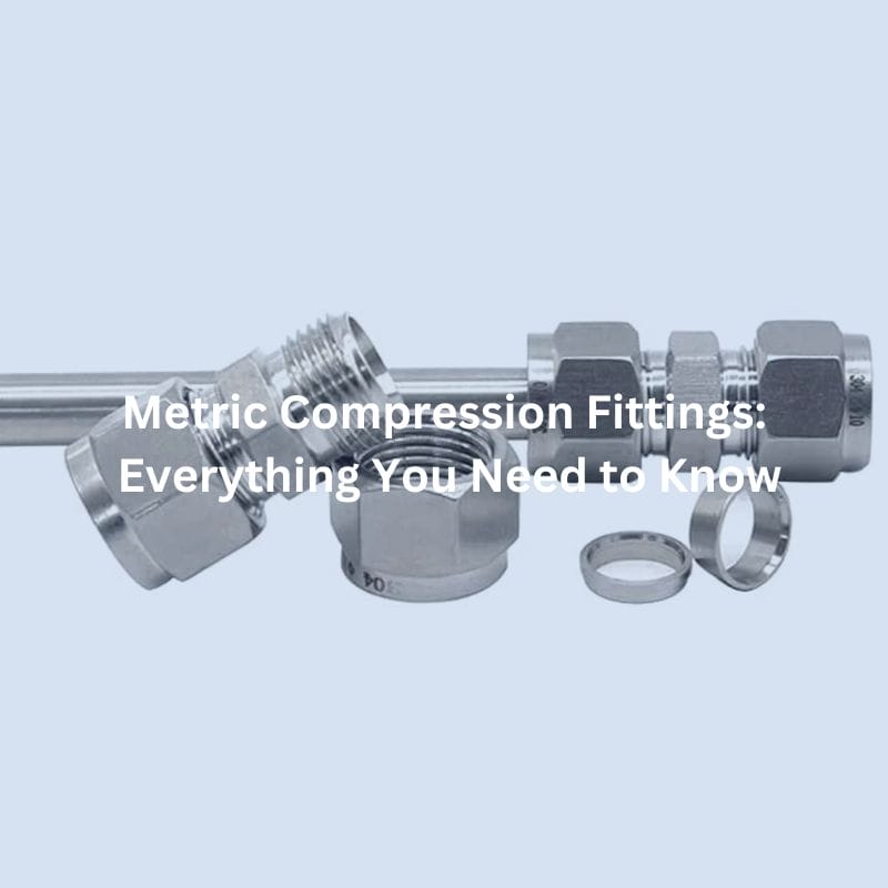
Metric Compression Fittings: Everything You Need to Know
Introduction
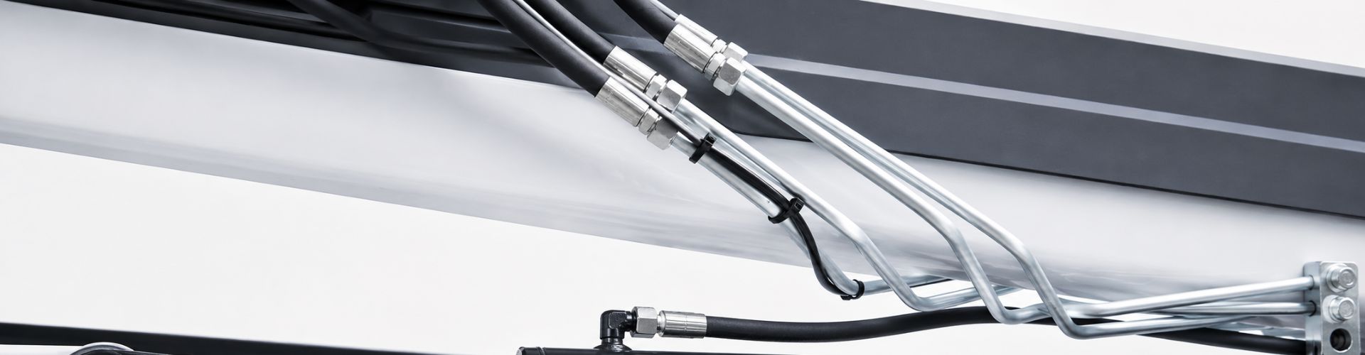
Metric Compression Fittings are critical components used to create secure, leak-proof connections in various piping and tubing systems. These fittings are designed to withstand high pressure and temperature, making them indispensable in industries such as hydraulics, pneumatics, automotive, plumbing, HVAC, aerospace, and defense. This post aims to provide a comprehensive understanding of metric compression hydraulic fittings, covering their definition, advantages, applications, working principles, and selection criteria. By exploring these aspects, we aim to equip you with the knowledge needed to make informed decisions when choosing and using Metric compression hydraulic fittings in your projects.
What Are Metric Compression Hydraulic Fittings?
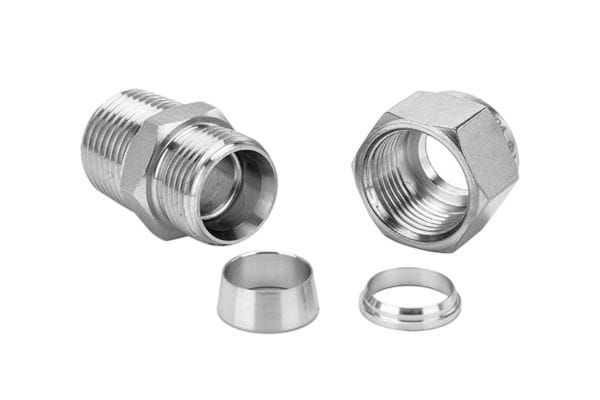
Metric compression hydraulic fittings are specialized connectors used to join sections of tubing or piping securely and without leakage. They are commonly utilized in various applications where maintaining the integrity of fluid or gas systems is crucial. The primary components of a metric compression fitting include a compression nut, a compression ring (or ferrule), and a fitting body. When the nut is tightened, it compresses the ring onto the tubing, creating a tight, secure seal that prevents leaks.

Types
Metric compression hydraulic fittings come in two main types: single ferrule and double ferrule.
Single Ferrule
Single ferrule fittings use one compression ring to create a seal between the tubing and the fitting body. The single ferrule design is simple and effective, providing a strong grip and seal with fewer components. These fittings are often chosen for applications where ease of installation and cost-effectiveness are priorities. They are widely used in various industries due to their reliability and straightforward design.
Double Ferrule
Double ferrule fittings feature two compression rings: a front ferrule and a back ferrule. The front ferrule creates a seal on the tubing surface while the back ferrule provides additional support and grip, enhancing the fitting’s overall performance. This design ensures a more secure connection and is particularly useful in high-pressure and high-vibration environments. Double ferrule fittings are known for their superior sealing capabilities and resistance to mechanical stress, making them ideal for critical applications.
Common Materials Used
Metric compression fittings are manufactured from various materials, each chosen for its specific properties and suitability for different applications. The most common materials include:
Stainless Steel: Known for its excellent corrosion resistance, strength, and durability, stainless steel is often used in harsh environments and applications requiring high levels of hygiene, such as in food processing, pharmaceutical, and chemical industries.
Brass: Brass fittings are popular for their good corrosion resistance, machinability, and thermal conductivity. They are widely used in plumbing, HVAC, and automotive applications due to their cost-effectiveness and reliability.
Other Materials: Depending on the specific requirements, Metric compression hydraulic fittings can also be made from other materials like plastic, copper, and various alloys. Each material offers unique advantages in terms of performance, cost, and suitability for different operating conditions.
Advantages
Leak-Proof Connections
One of the most significant advantages of Metric hydraulic compression fittings is their ability to create leak-proof connections. The compression mechanism ensures a tight seal between the fitting and the tubing, preventing any fluid or gas from escaping. This feature is critical in applications where even a minor leak can lead to significant safety hazards or operational inefficiencies.
High Pressure and Temperature Tolerance
Metric compression hydraulic fittings are designed to withstand high pressures and temperatures, making them suitable for demanding environments. They are constructed from robust materials like stainless steel and brass, which can endure extreme conditions without compromising performance. This high tolerance makes them ideal for applications in hydraulic systems, where pressures can be exceptionally high, and in environments with significant temperature variations, such as automotive or industrial processes.
Easy Installation and Maintenance
Another notable advantage of Metric compression hydraulic fittings is their ease of installation and maintenance. Unlike welded or soldered joints, compression fittings do not require specialized tools or equipment for installation. They can be quickly assembled using basic tools, which simplifies the installation process and reduces labor costs. Additionally, their design allows for easy disassembly and reassembly, facilitating straightforward maintenance and replacement without the need for complex procedures or significant downtime.
Applications
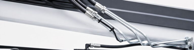
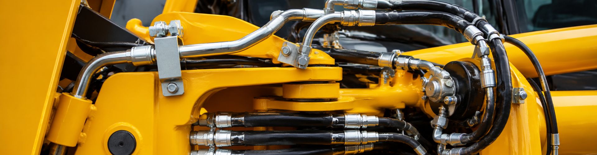
Hydraulic Systems
In hydraulic systems, where fluid power is used to perform various functions, maintaining high-pressure integrity is vital. Metric compression hydraulic fittings are commonly used to connect hydraulic lines and components, ensuring that the hydraulic fluid remains contained within the system. Their ability to withstand high pressures and prevent leaks makes them indispensable in heavy machinery, construction equipment, and industrial automation systems.
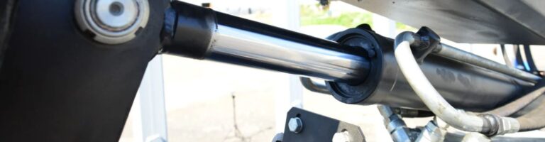
Automotive Applications
In the automotive industry, Metric compression hydraulic fittings are used in various systems, including fuel lines, brake systems, and air conditioning units. Their robust construction and ability to withstand high pressures and temperatures make them suitable for the demanding conditions encountered in vehicles. The fittings ensure that fluids, such as fuel and brake fluid, are securely transported without leaks, contributing to the overall safety and performance of the vehicle.
Plumbing and HVAC Systems
Metric compression hydraulic fittings are also extensively used in plumbing and HVAC (Heating, Ventilation, and Air Conditioning) systems. In plumbing, they provide secure connections for water supply lines, ensuring leak-free performance in residential, commercial, and industrial settings. In HVAC systems, these fittings are used to connect refrigerant lines, ensuring the efficient transfer of cooling or heating fluids. Their versatility and ease of installation make them a preferred choice for contractors and engineers in these applications.
Choosing the Right Metric Compression Fitting
Selecting the appropriate metric compression fitting for your application is crucial to ensure system integrity, safety, and performance. Several key factors must be taken into account during the selection process:
Material Compatibility
The material of the compression fitting must be compatible with the fluid or gas it will be in contact with and the operating environment. For example, stainless steel is often chosen for its excellent corrosion resistance, making it ideal for harsh environments and applications requiring high levels of hygiene, such as food processing and pharmaceuticals. Brass is favored for its good corrosion resistance, machinability, and thermal conductivity, making it suitable for plumbing, HVAC, and automotive applications. Choosing the wrong material can lead to premature failure, corrosion, or chemical reactions that compromise the system’s integrity.
Pressure and Temperature Ratings
It is essential to choose fittings that can withstand the maximum pressure and temperature conditions of your application. Each fitting comes with specified pressure and temperature ratings, which indicate the limits within which the fitting can operate safely. Exceeding these limits can lead to leaks, bursts, or other catastrophic failures. Therefore, always ensure that the selected fitting meets or exceeds the required specifications for your system’s operating conditions.
Sizing and Thread Type
Proper sizing is crucial for ensuring a secure and leak-free connection. Metric compression hydraulic fittings are available in various sizes, and selecting the correct size involves matching the fitting to the outside diameter of the tubing. Additionally, the thread type and pitch must be compatible with the mating components. Mismatched threads can lead to improper sealing, leaks, and mechanical failure. Always verify the thread type (e.g., parallel or tapered) and ensure it matches the mating parts.
Common Standards and Specifications
Metric compression hydraulic fittings are manufactured according to various standards and specifications to ensure compatibility and performance. Understanding these standards can help you select the right fittings for your application:
DIN (Deutsches Institut für Normung)
DIN standards are widely recognized and used in many industries worldwide. They cover various aspects of compression fittings, including dimensions, materials, and performance requirements. DIN-compliant fittings ensure high quality and compatibility with other DIN-standard components, making them a reliable choice for many applications.
ISO (International Organization for Standardization)
ISO standards provide internationally recognized guidelines for the design, manufacturing, and testing of compression fittings. ISO-compliant fittings are designed to meet stringent global standards, ensuring consistency, reliability, and interoperability across different regions and industries. Choosing ISO-compliant fittings can simplify sourcing and ensure compatibility with other ISO-standard components.
EN (European Norm)
EN standards are specific to the European Union and cover a wide range of industrial products, including compression fittings. EN standards ensure that fittings meet the necessary safety, quality, and performance criteria required in the European market. Using EN-compliant fittings can facilitate compliance with regional regulations and ensure high-quality performance.
Metric vs. Imperial Compression Fittings
Key Differences in Sizing and Standards
Metric and imperial compression fittings differ primarily in their sizing conventions and the standards they adhere to. Metric fittings are measured using the metric system, which uses millimeters (mm) as the unit of measurement for tubing outer diameters (OD). In contrast, imperial fittings use the imperial system, measuring tubing OD in inches.
Sizing
Metric Fittings: Sizes are expressed in millimeters (e.g., 6mm, 8mm, 10mm). This provides a more precise measurement system, particularly advantageous in applications requiring exact dimensions and tight tolerances.
Imperial Fittings: Sizes are expressed in fractions of an inch (e.g., 1/4″, 1/2″, 3/4″). The imperial system, while still widely used in certain regions and industries, offers less precision compared to the metric system.
Standards
Metric Standards: Adherence to standards such as DIN (Deutsches Institut für Normung), ISO (International Organization for Standardization), and EN (European Norm) ensure consistency, quality, and compatibility across a wide range of applications and regions.
Imperial Standards: These fittings typically adhere to standards set by organizations like SAE (Society of Automotive Engineers) and ASTM (American Society for Testing and Materials). While these standards are robust, they are primarily used in regions where the imperial system is predominant, such as the United States.

Advantages of Metric Fittings Over Imperial
Precision and Compatibility
Metric fittings offer greater precision due to their smaller unit measurements. This precision is crucial in applications requiring tight tolerances and exact dimensions, such as in high-performance hydraulic and pneumatic systems.
The widespread international adoption of the metric system facilitates easier sourcing and compatibility across different regions and industries, reducing the risk of mismatched components and improving supply chain efficiency.
Ease of Conversion and Standardization
The metric system’s simplicity, based on multiples of ten, makes calculations and conversions more straightforward compared to the imperial system, which uses fractions and different base units. This ease of use simplifies engineering design, manufacturing processes, and inventory management.
Global standardization around the metric system allows for more consistent manufacturing practices and quality control, ensuring that metric fittings meet stringent international standards and perform reliably in diverse applications.
Situations Where Imperial Fittings Might Be Preferred
Regional Preferences and Legacy Systems
In regions where the imperial system is still predominant, such as the United States, imperial fittings may be preferred due to existing infrastructure and legacy systems. Many industries and applications in these regions have long histories of using imperial measurements and switching to metric fittings might require significant changes to existing processes and equipment.
Maintenance and replacement parts for older systems designed with imperial fittings will often necessitate the continued use of imperial fittings to ensure compatibility.
Industry-Specific Requirements
Certain industries, particularly in North America, have specific standards and practices built around the imperial system. For example, the aerospace and automotive industries in the United States often use imperial fittings to comply with local standards and regulations.
In applications where equipment and components are primarily sourced from imperial-standard suppliers, maintaining consistency with imperial fittings can simplify procurement and reduce the risk of compatibility issues.
In summary, while Metric compression hydraulic fittings offer advantages in terms of precision, global compatibility, and ease of use, imperial fittings may still be preferred in regions with established legacy systems, industry-specific requirements, and user familiarity. Understanding the key differences and advantages of each system can help you make informed decisions when selecting the appropriate fittings for your specific applications.
Conclusion
In summary, Metric compression hydraulic fittings are essential components known for their precision, reliability, and versatility across various industries. They offer leak-proof connections, withstand high pressures and temperatures, and are easy to install and maintain. Understanding the differences between metric and imperial fittings, along with the importance of choosing the right materials and adhering to standards, ensures optimal performance in any application. For further information or to find the right fittings for your needs, consider contacting Topa.
FAQ
Metric compression hydraulic fittings are connectors used to join sections of tubing or piping securely, creating leak-proof connections in various fluid and gas systems.
Common materials include stainless steel, brass, and sometimes plastic or copper, each chosen based on the specific application requirements such as corrosion resistance and strength.
They provide leak-proof connections, high pressure and temperature tolerance, easy installation and maintenance, and versatility across different applications.
Consider factors such as material compatibility, pressure and temperature ratings, sizing, thread type, and adherence to relevant standards like DIN, ISO, and EN.
These fittings are used in hydraulic and pneumatic systems, automotive applications, plumbing, HVAC, aerospace, and defense industries.
Single ferrule fittings use one compression ring to seal the connection, while double ferrule fittings use two rings for enhanced sealing and grip, offering better performance in high-pressure and high-vibration environments.
Contact Topa
Have a question or suggestion? Fill out the form below to get in touch with one of our experts.


