Can You Use Teflon Tape on Brake Line Fittings

Can You Use Teflon Tape on Brake Line Fittings?

Can You Use Teflon Tape on Brake Line Fittings?

Table of Contents

Introduction

Ensuring the integrity and security of brake line fittings is crucial for vehicle safety, as even minor leaks or failures can lead to catastrophic consequences. This article addresses the common question: can you use Teflon tape on brake line fittings? We will explore the design and purpose of brake line fittings, the properties and uses of Teflon tape, and why it may not be suitable for such critical applications. Additionally, we will provide alternative solutions and best practices to ensure the reliability and safety of your brake system.

Understanding Brake Line Fittings

Brake line fittings are essential components in a hydraulic brake system, responsible for connecting various parts of the braking system and ensuring the secure transfer of brake fluid. These fittings create leak-proof seals that maintain the necessary pressure within the brake lines, allowing the hydraulic fluid to efficiently transfer force from the brake pedal to the brake calipers or wheel cylinders. This process ultimately brings the vehicle to a stop. The critical nature of brake line fittings cannot be overstated, as any failure or leak can lead to brake system malfunctions, putting the vehicle and its occupants at serious risk.

Types of Brake Line Fittings

There are several types of brake line fittings, each designed for specific applications within the brake system:

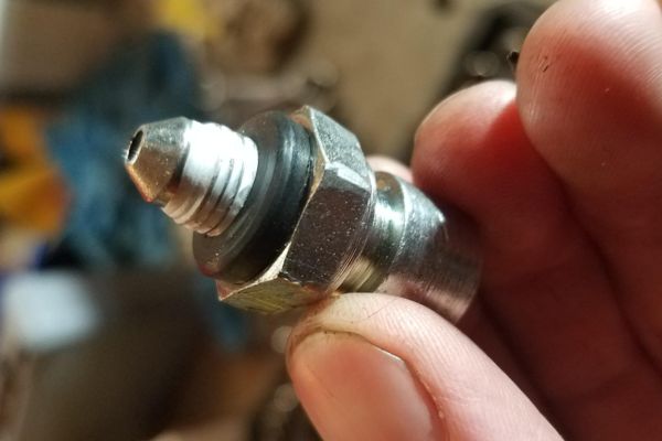
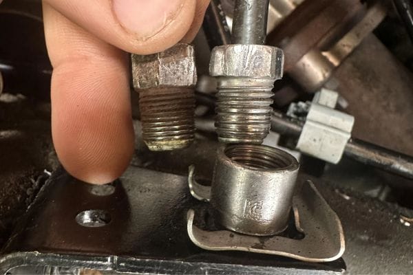
Inverted Flare Fittings: Commonly used in automotive brake systems, these fittings provide a strong, leak-proof connection by creating a flare at the end of the brake line that fits snugly into the fitting.

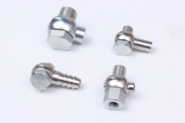
Banjo Fittings: Typically used in high-pressure hydraulic systems, banjo fittings feature a hollow bolt and spherical union, allowing fluid to flow through the fitting while providing a secure connection.

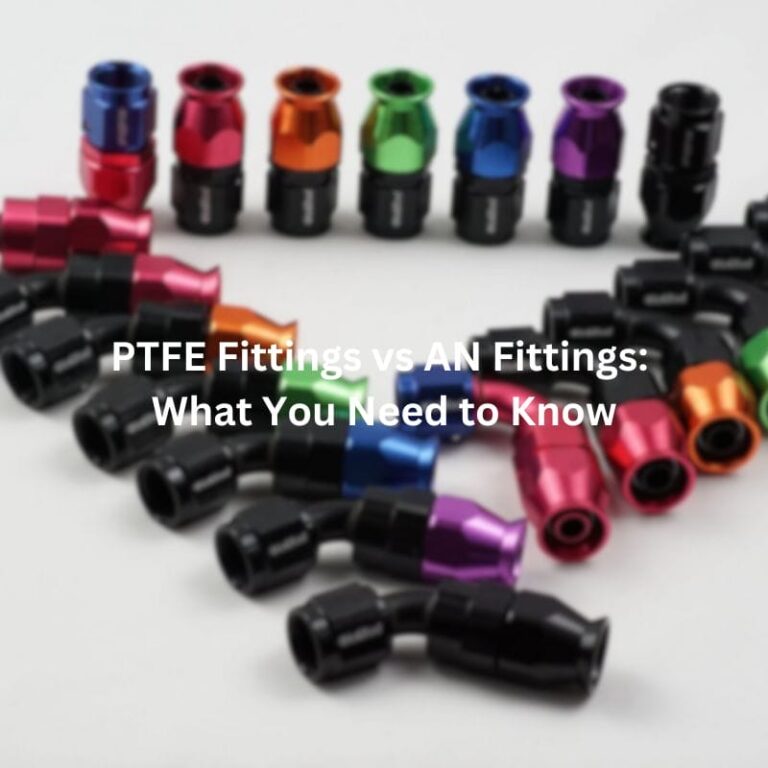
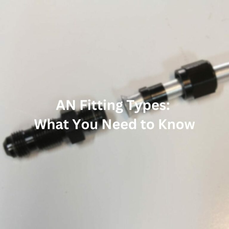
AN (Army-Navy) Fittings: Originally designed for military applications, AN fittings are known for their high durability and precision. They use a 37-degree flare to create a tight seal and are often found in performance and racing vehicles.

brake line fitting adapter supplier

Materials Commonly Used

Brake line fittings are typically made from materials that offer durability and resistance to corrosion, ensuring long-term reliability and performance. The most commonly used materials include:

Steel: Known for its strength and resistance to high pressure, steel fittings are widely used in automotive brake systems.

Brass: Valued for its corrosion resistance and ease of installation, brass fittings are often used in both automotive and industrial applications.

Understanding the different types and materials of brake line fittings is crucial for selecting the right components for your specific needs, ensuring the safety and efficiency of your hydraulic brake system.

What is Teflon Tape?

Composition and Characteristics

Teflon tape, also known as PTFE (Polytetrafluoroethylene) tape, is a thin, white film used to seal pipe threads. It comprises PTFE, a synthetic fluoropolymer of tetrafluoroethylene, known for its non-reactivity, high melting point, and low friction properties. These characteristics make Teflon tape an excellent sealing material, as it can withstand various temperatures and chemical exposures without degrading.

Common Uses

Teflon tape is widely used in various industries, primarily for its sealing capabilities. In plumbing, it is commonly applied to the threads of pipes and fittings to prevent leaks by creating a watertight seal. Additionally, it is used in other applications such as:

Gas Lines: To seal joints in gas piping systems, ensuring no leaks.

Aerospace and Automotive Industries: For sealing hydraulic and pneumatic systems.

Food and Beverage Industry: For applications requiring non-reactive and food-safe sealing materials.

teflon tape Topa

Advantages and Disadvantages

Advantages:

Sealing Threads: Teflon tape effectively fills gaps in threaded connections, preventing leaks.

Ease of Use: It is easy to apply, requiring only a few wraps around the thread to create a seal.

Chemical Resistance: Teflon tape is resistant to most chemicals, making it versatile for various applications.

Temperature Tolerance: It can withstand a broad range of temperatures, from very low to extremely high, without losing its sealing properties.

Disadvantages:

Compatibility Issues: Teflon tape is not suitable for all types of threads and connections. For instance, it is not recommended for use with certain plastics that may react with PTFE.

Over-application Risks: Over-wrapping or using excessive Teflon tape can lead to debris entering the system, potentially causing blockages or contamination.

Not Ideal for High-Pressure Systems: In some high-pressure applications, Teflon tape might not provide a reliable seal, leading to potential leaks or system failures.

The Compatibility of Teflon Tape with Brake Line Fittings

Brake Line Fitting Design

Brake line fittings are meticulously designed to create secure, leak-proof seals without the need for additional sealing materials like Teflon tape. These fittings achieve a tight seal through precision engineering, utilizing the shape and pressure of the fitting itself. Common designs include:

Inverted Flare Fittings: These fittings create a seal by forming a flare at the end of the brake line that fits perfectly into the mating surface of the fitting. The flare compresses to form a tight seal when the fitting is tightened.

AN (Army-Navy) Fittings: These fittings use a 37-degree flare to create a precise seal. The flare angle ensures that the surfaces of the fitting and the brake line form a leak-proof connection when properly torqued.

Banjo Fittings: These fittings use a banjo bolt and a spherical union to create a seal. The design allows fluid to pass through the hollow bolt while maintaining a tight connection.

Brake systems operate under extremely high pressure and require precise engineering to ensure that no leaks occur. The fittings must withstand these pressures without fail, as any breach could result in a loss of braking power and, consequently, vehicle safety.

Potential Issues with Teflon Tape

While Teflon tape is effective in many applications, it is generally not suitable for use with brake line fittings due to several reasons:

Risk of Contamination: Teflon tape can shed small particles during application, which can contaminate the brake fluid. These particles can clog small passages within the brake system, leading to malfunctions.

Improper Sealing: Brake line fittings are designed to create seals through precise metal-to-metal contact. Adding Teflon tape can interfere with this contact, preventing the fitting from sealing correctly. This can result in leaks, as the tape may not hold up under the high pressure of the brake system.

Compatibility Issues: Teflon tape is not designed to handle the high pressures and dynamic forces present in brake systems. Over time, the tape can degrade, leading to a loss of seal integrity.

Examples of Problems:

Leaks: The most immediate issue with using Teflon tape on brake line fittings is the potential for leaks. Even a small leak can lead to a significant loss of brake fluid, reducing braking efficiency or causing total brake failure.

Brake Failure: Contamination from Teflon tape particles can lead to blockages in the brake lines or within the brake calipers and cylinders. This can prevent the proper functioning of the braking system, leading to a dangerous situation where the brakes may fail to engage properly.

Maintenance Issues: Over time, Teflon tape can deteriorate under the high pressures and temperatures within the brake system. This deterioration can lead to the need for frequent maintenance and replacement of brake lines and fittings.

Alternative Solutions for Sealing Brake Line Fittings

Thread Sealants:

When it comes to sealing brake line fittings, suitable alternatives to Teflon tape are specifically designed to withstand the high pressures and conditions of hydraulic systems. One of the most effective alternatives is anaerobic thread sealants.

Anaerobic Thread Sealants: These sealants are designed to cure in the absence of air and in the presence of metal ions, making them ideal for metal-to-metal connections like brake line fittings. They provide a strong, durable seal that can handle the high pressures and temperatures of hydraulic systems without the risk of contamination or improper sealing.

Properties: These sealants remain in a liquid state when exposed to air, but once confined within the threads of the fitting, they harden to form a solid, leak-proof seal.

Advantages: Anaerobic sealants are resistant to most chemicals and fluids found in hydraulic systems, including brake fluid. They also do not degrade over time and maintain their sealing properties under dynamic conditions.

Proper Installation Techniques

Ensuring a secure and leak-free brake line fitting installation involves meticulous attention to detail and adherence to proper techniques. By following a structured approach, you can maintain the integrity and safety of your hydraulic brake system. Here’s a comprehensive step-by-step guide for installing brake line fittings without using Teflon tape:

Preparation

Clean the Threads:

Thorough Cleaning: Begin by ensuring that both the male and female threads of the brake line fittings are meticulously cleaned. Any debris, oil, or remnants of old sealant can compromise the seal. Use a wire brush, brake cleaner, or an appropriate cleaning tool to remove all contaminants. A clean surface is essential for the thread sealant to bond effectively.

Inspect the Fittings:

Detailed Inspection: Carefully inspect the fittings for any signs of damage, wear, or deformation. Even minor imperfections can lead to leaks or a failed connection. Replace any fittings that show signs of damage to ensure a secure and reliable seal. This step is crucial for maintaining the overall safety and functionality of the brake system.

Teflon Tape on Brake Line Fittings

Application of Thread Sealant

Choose the Right Sealant:

Selection Criteria: Select an anaerobic thread sealant specifically designed for hydraulic systems. Anaerobic sealants are ideal as they cure in the absence of air and in the presence of metal, forming a strong, leak-proof bond. Ensure the sealant is compatible with brake fluid and can withstand the high pressures of the brake system.

Apply the Sealant:

Proper Application: Apply a small, even amount of the anaerobic sealant to the male threads of the fitting. Spread it evenly around the threads, taking care to avoid excessive application. Excess sealant can cause contamination inside the brake line, which can lead to blockages or malfunction. Ensure that the sealant does not enter the brake line, as contamination can compromise the system’s effectiveness.

Assembly

Align the Fittings:

Accurate Alignment: Carefully align the male and female threads of the fittings to ensure they thread together smoothly. Proper alignment is critical to prevent cross-threading, which can damage the threads and compromise the seal. Misalignment can lead to a weak connection that may fail under pressure.

Hand Tighten:

Initial Tightening: Begin threading the fittings together by hand. This step helps ensure proper alignment and prevents cross-threading. Hand tightening allows you to feel if the threads are engaging correctly and to adjust as needed before applying full torque.

Torque Specifications

Use a Torque Wrench:

Precision Tightening: Once the fittings are hand-tight, use a torque wrench to tighten them to the manufacturer’s recommended torque specifications. Over-tightening can strip the threads or crack the fitting, while under-tightening can lead to leaks. A torque wrench ensures that the fittings are tightened to the precise torque required for a secure seal.

Check Specifications:

Refer to Guidelines: Always refer to the vehicle’s service manual or the fitting manufacturer’s guidelines for the correct torque values. These specifications are designed to ensure a safe and effective seal under operating conditions.

Final Inspection

Check for Leaks:

Visual Inspection: After tightening the fittings, inspect the connections for any signs of leaks. Wipe the area clean and look for any fluid seepage. Leaks can indicate improper installation or damage to the fittings, requiring immediate attention.

Pressure Test:

Confirm Seal Integrity: If possible, perform a pressure test on the brake system to ensure that the fittings are properly sealed and there are no leaks. A pressure test can reveal hidden issues that may not be visible during a visual inspection.

Regular Maintenance

Periodic Checks:

Routine Inspections: Regularly inspect the brake line fittings as part of routine vehicle maintenance. Look for any signs of wear, corrosion, or leaks, and address any issues promptly. Regular maintenance helps to identify and resolve potential problems before they lead to brake system failure.

By following these proper installation techniques and using suitable thread sealants, you can ensure the reliability and safety of brake line fittings. This meticulous approach helps maintain the integrity of the hydraulic brake system, ensuring optimal performance without the need for Teflon tape. Regular maintenance and adherence to manufacturer guidelines further enhance the longevity and effectiveness of the brake system, providing peace of mind and safety for vehicle operators.

Conclusion

To ensure the safety and reliability of your brake system, always use anaerobic thread sealants specifically designed for hydraulic applications. Follow proper installation techniques, including thorough cleaning of threads, careful alignment, and adherence to torque specifications. Regularly inspect your brake line fittings as part of routine maintenance and address any issues promptly.

FAQ

t is generally not recommended to use Teflon tape on brake line fittings due to the high-pressure requirements and the potential for contamination. Anaerobic thread sealants are a better alternative.

The best sealant for brake line fittings is an anaerobic thread sealant specifically designed for hydraulic systems. These sealants cure in the absence of air and form a strong, durable seal.

Apply a small amount of anaerobic thread sealant evenly around the male threads of the fitting. Ensure that the sealant does not enter the brake line itself to avoid contamination.

Always refer to the vehicle’s service manual or the fitting manufacturer’s guidelines for the correct torque specifications. Using a torque wrench ensures the fittings are tightened to the precise torque required for a secure seal.

After tightening the fittings, inspect the connections for any signs of leaks by wiping the area clean and looking for fluid seepage. If possible, perform a pressure test on the brake system to ensure that the fittings are properly sealed.

Regular maintenance helps to identify and resolve potential problems before they lead to brake system failure. Periodically checking for signs of wear, corrosion, or leaks ensures the longevity and effectiveness of your brake system.

Brake Line Fitting Types A Comprehensive Guide

Brake Line Fitting Types: A Comprehensive Guide

Brake Line Fitting Types: A Comprehensive Guide

Table of Contents

Introduction

Understanding brake line fitting types is crucial for vehicle safety and performance. These small but vital components ensure that brake fluid flows efficiently and effectively throughout the braking system, allowing for precise and reliable braking action. Brake line fittings connect various parts of the brake system, ensuring a secure and leak-free environment that is essential for maintaining optimal brake performance. This comprehensive guide will delve into the different types of brake line fittings, their applications, and how to choose the right one for your vehicle.

Basics of Brake Line Fittings

Definition and Function

Brake line fittings are essential components in a vehicle’s braking system that connect various parts of the brake lines, ensuring a secure and leak-free conduit for brake fluid. Their primary function is to facilitate the seamless transfer of brake fluid from the master cylinder to the brake calipers or wheel cylinders. This ensures that when the brake pedal is pressed, the hydraulic pressure generated is efficiently transmitted to the brakes, allowing for effective stopping power. Brake line fittings come in various shapes and sizes to accommodate different brake line types and configurations, playing a crucial role in maintaining the integrity and reliability of the braking system.

Materials Used

Brake line fittings are manufactured from a variety of materials, each chosen for its specific properties that contribute to the durability and performance of the braking system:

Steel: Steel fittings are highly durable and resistant to wear and tear, making them a popular choice for many vehicles. They are capable of withstanding high pressures and are relatively inexpensive, which makes them a standard material in many brake systems.

Brass: Brass fittings offer excellent resistance to corrosion and are easy to work with due to their malleability. They provide a good seal and are often used in areas where exposure to moisture and road salts is a concern. However, they may not be as strong as steel fittings and are typically used in lower-pressure applications.

Stainless Steel: Stainless steel fittings combine the strength of steel with superior corrosion resistance. They are particularly suitable for high-performance and off-road vehicles where brake lines are exposed to harsh conditions. Although they are more expensive, their durability and longevity often justify the cost in demanding applications.

Types of Brake Lines

Brake lines are the conduits through which brake fluid travels from the master cylinder to the brake calipers or wheel cylinders. Different types of brake lines are used based on the specific requirements of the vehicle and its braking system:

Steel Brake Lines: These are the most common type of brake lines used in vehicles. Steel brake lines are strong and capable of withstanding high pressure, making them ideal for most standard applications. However, they can be prone to rust and corrosion if not properly maintained or if exposed to harsh environmental conditions.

Rubber Brake Lines: Rubber brake lines are flexible and easy to install, making them a common choice for connecting the brake caliper to the hard brake lines on the vehicle’s chassis. They provide a good balance of flexibility and durability but can degrade over time due to exposure to brake fluid and environmental factors. Regular inspection and replacement are necessary to maintain optimal performance.

Braided Stainless Steel Brake Lines: These brake lines consist of a Teflon or rubber inner tube wrapped in a braided stainless steel mesh. The stainless steel braid provides added strength and protection, reducing the risk of expansion under pressure and improving brake pedal feel. They are particularly favored in high-performance and racing applications where precise braking is critical. While they offer superior performance, they also come at a higher cost compared to standard rubber brake lines.

Common Types of Brake Line Fittings

Inverted Flare Fittings

Inverted flare fittings, also known as double flare fittings, are one of the most common types of brake line fittings used in automotive applications. They feature a 45-degree flare at the end of the brake line, which is folded back onto itself to create a double-layered flare. This design provides a secure and leak-proof connection, capable of withstanding high pressures. Inverted flare fittings are widely used in both domestic and imported vehicles, especially in systems where reliability and durability are paramount. They are commonly found in brake, fuel, and transmission systems.

Bubble Flare Fittings

Bubble flare fittings, also known as ISO or DIN flare fittings, are commonly used in European and some Japanese vehicles. These fittings have a single flare that creates a bubble shape at the end of the brake line. The bubble flare provides a reliable seal when connected to the corresponding female fitting. While they are less common in North American vehicles, bubble flare fittings are essential for ensuring compatibility and proper function in vehicles designed with this standard. They are typically used in hydraulic brake and clutch systems.

AN (Army-Navy) Fittings

AN fittings, which stand for Army-Navy fittings, are high-performance fittings originally developed for military and aerospace applications. These fittings have a 37-degree flare and are known for their robustness and precision. AN fittings are often used in high-performance, racing, and custom automotive applications due to their ability to provide a secure, high-pressure connection. They are available in various sizes and materials, including aluminum and stainless steel, making them versatile for different uses. AN fittings are not typically found in standard automotive brake systems but are favored in performance and custom builds.

Banjo Fittings

Banjo fittings are distinctive in their design, featuring a hollow bolt and spherical union, which allows for fluid transfer through the bolt and around the spherical fitting. This design enables a 360-degree rotation, providing flexibility in routing brake lines and making them ideal for tight or awkward spaces. Banjo fittings are commonly used in hydraulic brake systems, particularly in motorcycles and bicycles, as well as in automotive applications where space constraints exist. They provide a reliable and compact solution for connecting brake lines to calipers, master cylinders, and other components.

Banjo Bolt Usage

Quick-Connect Fittings

Quick-connect fittings are designed for ease of installation and removal without the need for specialized tools. These fittings typically feature a push-to-connect mechanism that locks the fitting in place, ensuring a secure and leak-free connection. Quick-connect fittings are commonly used in modern automotive applications, including brake and fuel systems, where serviceability and efficiency are essential. They are particularly useful in assembly lines and repair environments, where reducing installation time is a priority. These fittings are often made from durable plastics and metals, providing a reliable connection while simplifying maintenance.

Push Connect Fittings

Push connect fittings, similar to quick-connect fittings, are designed for fast and easy installation. These fittings allow the brake line to be pushed into the fitting, where an internal mechanism locks the line in place. This design eliminates the need for flaring tools and reduces the risk of leaks due to improper installation. Push connect fittings are commonly used in pneumatic and hydraulic systems, including brake systems, where they provide a secure connection with minimal effort. They are often used in conjunction with flexible brake lines and are favored in applications where quick assembly and disassembly are required.

Choosing the Right Brake Line Fitting

Vehicle Type and Application

Choosing the right brake line fitting begins with understanding the specific requirements of your vehicle and its intended application. Different vehicles have unique braking system designs and requirements, which influence the type of fittings that are most suitable:

Passenger Vehicles: For standard passenger cars, OEM (Original Equipment Manufacturer) fittings are usually the best choice as they are designed to meet the specific requirements of the vehicle. Inverted flare fittings are commonly used in these vehicles due to their reliability and compatibility with most brake systems.

Commercial Vehicles: Trucks and buses often require more robust fittings due to the higher pressures and heavier loads they handle. Stainless steel fittings or heavy-duty brass fittings are often recommended to ensure durability and longevity under demanding conditions.

Performance and Racing Vehicles: High-performance vehicles, including sports cars and race cars, often benefit from AN fittings. These fittings provide a secure, high-pressure connection that can withstand the increased demands of performance driving. Additionally, braided stainless steel brake lines paired with AN fittings can improve brake response and pedal feel.

Off-Road and Utility Vehicles: Off-road vehicles and utility vehicles, such as ATVs and UTVs, typically face harsh environments and require fittings that can withstand exposure to dirt, moisture, and extreme conditions. Banjo fittings and stainless steel fittings are ideal for these applications due to their strength and corrosion resistance.

Performance Needs

When upgrading a vehicle’s braking system for enhanced performance, selecting the right brake line fittings is crucial. Performance upgrades often involve higher pressures and more demanding conditions, making the choice of fittings particularly important:

High-Pressure Tolerance: AN fittings are a popular choice for performance applications due to their ability to handle higher pressures. These fittings are commonly used in racing and high-performance vehicles to ensure that the braking system remains reliable under extreme conditions.

Improved Brake Response: Upgrading to braided stainless steel brake lines can significantly improve brake response and pedal feel. These lines, when paired with high-quality fittings like AN or inverted flare fittings, reduce the expansion of the brake line under pressure, providing a more direct and responsive braking experience.

Custom and High-Performance Builds: Custom vehicles often require specialized fittings to accommodate unique designs and configurations. In these cases, consulting with a professional or referring to performance parts catalogs can help identify the best fittings for your specific build.

Compatibility and Standards

Ensuring compatibility and adherence to industry standards is essential when selecting brake line fittings. Using the wrong type of fitting can lead to leaks, brake failure, and potential safety hazards:

OEM Specifications: Always check the vehicle manufacturer’s specifications for brake line fittings. Using fittings that match the OEM specifications ensures compatibility and maintains the integrity of the braking system.

Industry Standards: Familiarize yourself with industry standards such as SAE and DOT regulations. For example, SAE J1401 is a standard that specifies performance requirements for hydraulic brake hose assemblies, including the fittings. Compliance with these standards ensures that the fittings are safe and reliable for use in automotive applications.

Material Compatibility: Ensure that the fittings you choose are compatible with the brake line material. For instance, stainless steel fittings are often used with braided stainless steel brake lines, while brass fittings may be more suitable for rubber brake lines. Using compatible materials helps prevent corrosion and ensures a secure connection.

Size and Thread Type: Brake line fittings come in various sizes and thread types. It is crucial to match the fitting size and thread type to the brake lines and components being used. Mismatched sizes or thread types can result in leaks and compromised braking performance.

Troubleshooting Brake Line Fitting Issues

Identifying Common Problems

Effective troubleshooting begins with identifying the common problems associated with brake line fittings. Here are some of the most frequent issues you might encounter:

Leaks: Leaks in brake line fittings can be caused by several factors, including improper installation, damaged flares, or worn-out seals. Leaks often result in a spongy brake pedal feel and reduced braking efficiency. They can be visually identified by wet spots or brake fluid dripping from the fittings.

Corrosion: Corrosion is a common issue, especially in areas with high humidity or where road salts are used during winter. Corroded fittings can weaken over time, leading to leaks and potential failure. Corrosion is typically identified by the presence of rust or a whitish powder on the surface of the fittings.

Fitting Failures: Fitting failures can occur due to manufacturing defects, excessive pressure, or physical damage. Common signs of fitting failure include cracks, deformities, and complete disconnection of the brake line from the fitting. This issue often results in immediate and significant brake fluid loss.

Brake Line Fittings install

Solutions and Repairs

Addressing issues with brake line fittings requires a systematic approach to ensure the problems are resolved effectively and safely. Here are some steps to tackle common issues:

Leak Repairs:

Inspection: Begin by thoroughly inspecting the brake line fittings and the surrounding areas to pinpoint the source of the leak. Check for loose connections, damaged flares, and worn-out seals.

Tightening: If the leak is due to a loose connection, carefully tighten the fitting using the appropriate tools. Avoid over-tightening, as this can damage the fitting and flare.

Flare Repair: If the flare is damaged, it may need to be re-flared. Cut off the damaged section of the brake line, re-flare the end using a quality flaring tool, and reconnect the fitting.

Seal Replacement: For leaks caused by worn-out seals, replace the seals with new ones. Ensure that the new seals are compatible with the fitting type and brake fluid used.

Corrosion Mitigation:

Cleaning: Light surface corrosion can be cleaned using a wire brush or a mild abrasive pad. Be gentle to avoid damaging the fitting.

Replacement: For severe corrosion, especially if it affects the integrity of the fitting, replacement is the best option. Use corrosion-resistant fittings, such as those made from stainless steel or brass, to prevent future issues.

Protective Coating: Apply a protective coating or use corrosion-resistant brake fluid to minimize the risk of future corrosion. Regularly inspect and maintain the brake lines and fittings to catch any early signs of corrosion.

Fitting Failure Solutions:

Immediate Action: If a fitting failure is identified, do not attempt to drive the vehicle. Brake fluid loss can lead to brake failure, posing a serious safety risk.

Replacement: Replace the failed fitting with a new, high-quality fitting that meets the manufacturer’s specifications. Ensure the replacement fitting is properly installed and secured.

System Bleeding: After replacing a fitting, bleed the brake system to remove any air bubbles that may have entered during the repair process. Proper bleeding is crucial to restore full braking power and responsiveness.

Preventive Measures

In addition to addressing existing issues, implementing preventive measures can help avoid future problems with brake line fittings:

Regular Inspections: Conduct regular inspections of the brake lines and fittings to catch any issues early. Look for signs of wear, corrosion, and leaks.

Quality Components: Use high-quality fittings and brake lines that meet or exceed OEM specifications. Investing in quality components can prevent many common issues.

Proper Installation: Ensure that all fittings are properly installed according to manufacturer guidelines. Use the correct tools and techniques to avoid damage during installation.

Environmental Protection: Protect brake lines and fittings from harsh environmental conditions. If driving in areas where road salts are used, wash the undercarriage of the vehicle regularly to remove salt residues.

Conclusion

In summary, understanding the various types of brake line fittings, their specific uses, and how to choose the right one for your vehicle is crucial for maintaining a safe and effective braking system. Take action now to inspect your vehicle’s brake lines and fittings, replace any worn or damaged components, and stay proactive with regular maintenance. Ensuring your brake system is in top condition not only improves vehicle performance but also ensures your safety and the safety of others on the road.

FAQ

Brake line fittings are components that connect various parts of the brake system, ensuring a secure and leak-free conduit for brake fluid.

Different types of brake line fittings, such as inverted flare, bubble flare, and AN fittings, are designed to meet specific performance requirements and compatibility needs for various vehicles and applications.

The right brake line fitting depends on your vehicle type, performance needs, and compatibility with existing systems. Refer to your vehicle’s manufacturer specifications or consult with a professional mechanic.

Common signs include leaks (visible brake fluid), corrosion (rust or whitish powder on fittings), and fitting failures (cracks or disconnections).

Yes, if you have the necessary tools and knowledge. However, for safety reasons, it’s often best to have a professional handle brake line fitting replacements and repairs.

Regular inspections are recommended at least once a year or during routine maintenance checks to ensure there are no leaks, corrosion, or other issues.

Brake Line Fitting Repair A Step-by-Step Guide

Brake Line Fitting Repair: A Step-by-Step Guide

Brake Line Fitting Repair: A Step-by-Step Guide

Table of Contents

Introduction

The brake system is one of the most critical safety components in any vehicle. Ensuring that every part of this system is functioning correctly is paramount to the safety of the driver and passengers. Among these components, brake line fittings play a crucial role in maintaining the integrity of the brake system. They ensure that the hydraulic pressure needed for braking is consistently delivered, allowing the vehicle to stop effectively. Over time, however, these fittings can wear out or become damaged due to various factors such as corrosion, physical impact, or regular wear and tear. This is why understanding how to repair brake line fittings is essential for any vehicle owner or mechanic.

Understanding Brake Line Fittings

Brake line fittings are essential components in a vehicle’s braking system, serving as connectors between brake lines and various parts of the brake system, such as calipers, wheel cylinders, and master cylinders. These fittings ensure a secure and leak-proof connection, enabling the hydraulic pressure generated by the brake pedal to be transmitted efficiently to the brake pads or shoes. This pressure is what ultimately allows the vehicle to slow down or stop. Given their critical role, brake line fittings must be in good condition and properly maintained.

Different Types of Brake Line Fittings

There are several types of brake line fittings, each designed for specific applications and connection types. The most common types include:

Inverted Flare Fittings: These are widely used in many vehicles and feature a flared end that fits into a corresponding female fitting. The inverted flare provides a strong and secure connection, minimizing the risk of leaks under high pressure.

Bubble Flare Fittings: Similar to inverted flare fittings, bubble flare fittings have a slightly different flare shape. They are commonly used in European and Japanese vehicles. The bubble flare fitting creates a reliable seal, ensuring efficient hydraulic pressure transfer.

Banjo Fittings: These fittings are used in applications where space is limited. Banjo fittings consist of a hollow bolt and spherical union, allowing brake fluid to pass through the fitting even when the connection is at a right angle. They are often used in motorcycle brake systems and some automotive applications.

Brake Line Fitting broken

Signs That Brake Line Fittings Need Repair or Replacement

Regular inspection of brake line fittings is crucial to maintaining a safe and reliable brake system. Here are some signs that indicate brake line fittings may need repair or replacement:

Leaks: Any sign of brake fluid leaking around the fittings is a clear indication that the fitting may be damaged or not properly secured. Leaks can lead to a loss of hydraulic pressure, reducing braking efficiency.

Corrosion: Visible rust or corrosion on the fittings can weaken the connection and lead to potential leaks or failure. Corroded fittings should be replaced to ensure the integrity of the brake system.

Cracks or Damage: Physical damage, such as cracks or dents in the fittings, can compromise their ability to maintain a secure seal. Damaged fittings should be replaced immediately.

Soft Brake Pedal: A soft or spongy brake pedal can indicate air in the brake lines or a loss of hydraulic pressure, possibly due to a faulty fitting. Inspecting and replacing faulty fittings can help restore the proper brake pedal feel.

Braking Performance: Any noticeable decline in braking performance, such as increased stopping distances or reduced braking power, warrants an inspection of the brake line fittings and other components of the brake system.

Preparing for the Repair

Before diving into the repair of brake line fittings, it is essential to take proper safety precautions and prepare the vehicle to ensure a smooth and secure process. Here’s how to get started:

Safety Precautions Before Starting the Repair

Wear Appropriate Safety Gear: Safety should always be a top priority. Wear safety glasses to protect your eyes from debris and brake fluid, which can be harmful if it comes into contact with your eyes. Gloves are also recommended to protect your hands from sharp edges and corrosive brake fluid.

Work in a Well-Ventilated Area: Brake fluid is toxic and has harmful fumes. Ensure you are working in a well-ventilated area or use a fan to circulate air and reduce exposure to fumes.

Keep a Fire Extinguisher Handy: Although it is rare, working with brake fluid carries a slight risk of fire. Having a fire extinguisher nearby can provide an added layer of safety.

Use Jack Stands and Chocks: Never rely solely on a jack to support the vehicle. Use jack stands to secure the vehicle and wheel chocks to prevent it from rolling.

Steps to Lift and Secure the Vehicle

Locate the Jack Points: Consult your vehicle’s manual to find the proper jack points. These are reinforced areas of the vehicle designed to support its weight.

Use a Hydraulic Jack: Place the hydraulic jack under the designated jack point and lift the vehicle slowly until the wheels are off the ground.

Place Jack Stands: Once the vehicle is lifted, place jack stands under the frame or other sturdy areas recommended by the vehicle manufacturer. Lower the vehicle onto the jack stands carefully, ensuring it is securely supported.

Secure the Wheels: Use wheel chocks to block the wheels that remain on the ground to prevent any movement.

How to Locate the Brake Line Fittings Needing Repair

Identify the Problem Area: If you have already identified a leak or specific issue, locate that area first. The brake line fittings in question are often near the leak.

Inspect Brake Lines: Follow the brake lines from the master cylinder to the calipers or wheel cylinders. Check for any signs of corrosion, damage, or leakage along the lines and fittings.

Check Fittings at Key Points: Inspect the fittings at key connection points, such as where the brake lines connect to the master cylinder, along the brake lines at junction points, and at the calipers or wheel cylinders.

Look for Wear and Tear: Pay close attention to areas where brake lines are subjected to movement or are close to suspension components. These areas are more prone to wear and damage.

Removing the Damaged Brake Line Fittings

Properly removing damaged brake line fittings is crucial for a successful repair. This process requires patience, the right tools, and careful attention to detail to avoid further damage to the brake system. Here’s a comprehensive guide to help you through this critical step:

Prepare the Work Area: Ensure the vehicle is securely lifted and supported on jack stands. Gather all necessary tools, including flare nut wrenches, a tubing cutter, and a penetrating oil.

Locate the Damaged Fittings: Identify the specific brake line fittings that need to be removed. These are usually found at connection points along the brake lines, such as where the lines connect to the master cylinder, brake calipers, or wheel cylinders.

Apply Penetrating Oil: Spray penetrating oil onto the fitting and the surrounding area. Allow it to sit for a few minutes to loosen any rust or debris that may be causing the fitting to stick.

Loosen the Fitting: Use a flare nut wrench to grip the fitting securely. A flare nut wrench is specifically designed to prevent rounding off the fitting. Turn the wrench counterclockwise to loosen the fitting. If the fitting is extremely tight or rusted, apply more penetrating oil and gently tap the fitting with a hammer to help break it free.

Hold the Brake Line Steady: While loosening the fitting, use another wrench to hold the brake line steady. This prevents the line from twisting or bending, which could cause additional damage.

Remove the Fitting: Once the fitting is loose, carefully unscrew it by hand. Be prepared for some brake fluid to leak out; have a container ready to catch any fluid and prevent it from spilling onto the floor.

Inspect the Brake Line: After removing the fitting, inspect the brake line for any signs of damage or corrosion. If the line itself is damaged, it may also need to be replaced.

Brake Line Fittings install

Tips for Loosening Stuck Fittings

Heat Application: If the fitting is severely stuck, use a heat gun to gently warm the fitting. This can help expand the metal and make it easier to loosen. Be cautious not to overheat and damage surrounding components.

Impact Wrench: In some cases, an impact wrench can be used to apply short, powerful bursts of torque to break free stubborn fittings. Use this tool carefully to avoid damaging the fitting or brake line.

Vise Grips: If the fitting is already rounded off or heavily corroded, vise grips may provide better grip than a wrench. However, this should be a last resort, as it can further damage the fitting.

How to Properly Dispose of Old Brake Line Fittings

Collect the Fittings: Place the removed fittings and any cut sections of brake line into a container. This keeps the work area clean and helps prevent brake fluid spills.

Dispose of Brake Fluid: Brake fluid is hazardous and should not be poured down the drain or onto the ground. Collect any drained fluid in a sealed container and take it to a local automotive shop or recycling center that accepts hazardous waste.

Recycle Metal Fittings: Most metal brake line fittings can be recycled. Separate the metal parts from any non-metal components and take them to a scrap metal recycling facility.

Cutting and Flaring New Brake Lines

Properly cutting and flaring new brake lines is essential for ensuring a secure and leak-proof connection in your vehicle’s brake system. This process requires precision and the right tools. Here’s a detailed guide to help you through these steps:

Instructions for Measuring and Cutting the Brake Line to the Correct Length

Measure the Old Brake Line: If you are replacing an existing brake line, measure the old line from end to end using a tape measure. This will give you the exact length needed for the new brake line.

Account for Fittings: When measuring, ensure you account for the length needed to accommodate the fittings. The fitting will add a small amount of length to the overall line, so it’s essential to include this in your measurement.

Mark the New Brake Line: Once you have the correct measurement, use a marker to mark the new brake line where it needs to be cut.

Use a Tubing Cutter: Secure the brake line in a tubing cutter, ensuring the cutting wheel is aligned with your mark. Tighten the cutter and rotate it around the line, gradually tightening the cutter with each turn until the line is cleanly cut. A tubing cutter ensures a straight, clean cut, which is crucial for creating a proper flare.

Deburr the Cut Edge: After cutting the brake line, use a deburring tool or a small file to remove any sharp edges or burrs from the cut end. This helps to ensure a smooth, even flare.

Step-by-Step Guide to Flaring the Brake Line Ends

Select the Correct Flare Tool: Ensure you are using a flaring tool that matches the type of flare required for your brake system, such as a double flare or bubble flare tool.

Prepare the Brake Line: Insert the brake line into the appropriate hole in the flaring tool’s clamp. The end of the line should extend slightly beyond the clamp, matching the depth required for the specific flare type.

Secure the Line: Tighten the clamp securely to hold the brake line in place. Ensure the line is straight and properly aligned within the tool.

Create the Initial Flare: For a double flare, place the flaring die (usually shaped like a small cone) over the brake line end. Position the flaring tool’s yoke over the die and screw the flaring cone down onto the brake line. Tighten until the line is compressed into the first stage of the flare.

Complete the Double Flare: Remove the die and tighten the flaring tool again to fold the initial flare back into itself, creating a double flare. This second stage reinforces the flare, making it stronger and more durable.

Inspect the Flare: Remove the brake line from the flaring tool and inspect the flare for evenness and smoothness. The flare should be symmetrical, with no cracks or uneven edges.

Installing New Brake Line Fittings

Installing new brake line fittings is a critical step in ensuring the reliability and safety of your vehicle’s brake system. Proper installation ensures a leak-proof connection, maintains hydraulic pressure, and ultimately contributes to effective braking performance. Here’s a detailed guide on how to install new brake line fittings, ensure proper alignment and tightness, and check for proper fitment.

Detailed Instructions for Installing New Fittings

Brake Line Fitting Guide

Prepare the Brake Line and Fittings:

Ensure the new brake line and fittings are clean and free of any debris.

Double-check that you have the correct type of fittings for your vehicle’s brake system (e.g., inverted flare, bubble flare, banjo fittings).

Slide the Nut Onto the Brake Line:

Before flaring the brake line, remember to slide the fitting nut onto the line. The threaded end should face the flared end of the brake line.

Position the Fitting:

Place the new fitting into the appropriate position on the brake component (e.g., master cylinder, brake caliper, wheel cylinder). Ensure the fitting is seated properly in its socket.

Insert the Flared Brake Line:

Carefully insert the flared end of the brake line into the fitting. Ensure the flare seats are properly against the fitting’s mating surface.

Thread the Nut Onto the Fitting:

Hand-tighten the nut onto the fitting to ensure it threads correctly. This helps prevent cross-threading, which can damage the fitting and the brake line.

Tighten the Fitting:

Using a flare nut wrench, tighten the nut securely. Flare nut wrenches are designed to grip the fitting firmly and prevent rounding off the edges.

Follow the manufacturer’s torque specifications to avoid over-tightening or under-tightening the fitting.

Bleeding the Brake System

Importance of Bleeding the Brake System After Repair

Bleeding the brake system is a crucial step after any brake line or fitting repair. This process removes air bubbles that can become trapped in the brake lines during the repair. Air in the brake lines can compress under pressure, leading to a spongy brake pedal and reduced braking efficiency. Properly bleeding the brakes ensures that the hydraulic pressure is consistently and effectively transmitted through the brake fluid, maintaining optimal braking performance and safety.

Step-by-Step Guide to Bleeding the Brakes

There are several methods to bleed the brakes, including gravity bleeding, manual bleeding, and using a vacuum pump. Here’s a step-by-step guide for each method:

Gravity Bleeding

Prepare the Vehicle:

Ensure the vehicle is on a level surface.

Check the brake fluid reservoir and top it up if necessary.

Open the Bleeder Valve:

Starting with the brake farthest from the master cylinder (usually the right rear wheel), locate the bleeder valve on the brake caliper or wheel cylinder.

Attach a clear plastic hose to the bleeder valve and place the other end in a container to catch the brake fluid.

Open the Valve and Wait:

Open the bleeder valve and allow gravity to pull the brake fluid through the system. This can take several minutes.

Keep an eye on the fluid level in the reservoir and ensure it doesn’t drop too low.

Close the Valve:

Once the fluid runs clear and free of air bubbles, close the bleeder valve securely.

Repeat the process for each wheel, moving closer to the master cylinder.

Gravity Bleeding

Prepare the Vehicle and Tools:

Have a helper sit in the driver’s seat to press the brake pedal.

Ensure the brake fluid reservoir is full.

Attach the Bleeder Hose:

Attach a clear hose to the bleeder valve and place the other end in a container.

Press and Hold the Brake Pedal:

Have the helper press and hold the brake pedal down.

Open the Bleeder Valve:

Open the bleeder valve to release fluid and air. The pedal will drop as fluid escapes.

Close the valve before the helper releases the pedal to prevent air from re-entering the system.

Repeat the Process:

Repeat the press, hold, open, close sequence until the fluid runs clear and bubble-free.

Move to the next wheel and repeat the process.

Using a Vacuum Pump

Prepare the Vacuum Pump:

Attach the vacuum pump to the bleeder valve using the appropriate adapter and a clear hose.

Create a Vacuum:

Pump the vacuum to create suction. This will draw fluid and air out of the system.

Open the Bleeder Valve:

Open the bleeder valve to allow the vacuum to pull the fluid through.

Monitor the Fluid:

Watch the fluid in the clear hose for air bubbles. Continue until the fluid is clear.

Close the Valve:

Close the bleeder valve while maintaining suction to prevent air from entering.

How to Check for Air in the Brake Lines

Pedal Feel:

After bleeding, the brake pedal should feel firm and responsive. A spongy pedal indicates that air remains in the system and further bleeding is required.

Brake Fluid Inspection:

Inspect the brake fluid in the reservoir. It should be clear and free of bubbles.

Test Drive:

Conduct a short, cautious test drive to ensure the brakes respond correctly and the pedal remains firm.

Conclusion

Proper brake line fitting repair is crucial for ensuring the safety and reliability of your vehicle’s braking system. This guide has provided a comprehensive step-by-step approach to identifying, repairing, and maintaining brake line fittings. By following these detailed instructions, you can perform safe and effective repairs, ensuring that your brakes function optimally and your vehicle remains secure on the road. By investing time and effort into learning and performing brake line fitting repairs, you are taking a significant step towards ensuring a safer driving experience.

FAQ

Damaged brake line fittings can lead to brake fluid leaks, reducing hydraulic pressure and compromising braking performance. Timely repair or replacement ensures your brakes remain effective and your vehicle stays safe.

Essential tools include flare nut wrenches, a tubing cutter, a flaring tool kit, and a brake bleeder kit. Safety gear like gloves and safety glasses are also recommended.

Signs include visible leaks, rust or corrosion on the fittings, cracks or physical damage, a spongy brake pedal, and decreased braking performance.

Common types include inverted flare fittings, bubble flare fittings, and banjo fittings. The type used depends on the vehicle make and model.

It’s advisable to inspect your brake line fittings during regular vehicle maintenance checks, especially if you notice any signs of brake issues or during seasonal changes when road conditions can affect brake components.

If you have the necessary tools and follow proper safety procedures, you can perform the repairs yourself.

Stop Brake Line Leaking at Fitting with These Simple Steps

Stop Brake Line Leaking at Fitting with These Simple Steps

Stop Brake Line Leaking at Fitting with These Simple Steps

Table of Contents

Introduction

Brake system failures are a major safety concern, with brake line issues being a significant factor. According to the National Highway Traffic Safety Administration (NHTSA), approximately 22% of vehicle-related accidents stem from brake system malfunctions. Ensuring that your brake lines are free from leaks is not just a maintenance task—it’s essential for preventing potentially catastrophic accidents. In this guide, you will discover practical steps for identifying and repairing brake line leaks at fittings. We will cover how to detect the signs of a leak, explore the common causes, and walk you through a detailed repair process.

Understanding Brake Line Leaks

What is a Brake Line Leak?

A brake line leak occurs when there is a breach or cracks in the brake line, causing brake fluid to escape from the system. Brake lines are metal or flexible tubes designed to transport hydraulic brake fluid from the master cylinder to the brake calipers or drums. The brake fluid is essential for creating the hydraulic pressure needed to engage the brakes. When a brake line leaks, the brake fluid level drops, reducing the pressure in the system. This loss of pressure impairs the brakes’ effectiveness, making it difficult to stop the vehicle safely.

How Leaks Affect the Brake System’s Performance

A leaking brake line can have several adverse effects on your vehicle’s braking performance:

Reduced Braking Power: As brake fluid leaks out, the remaining fluid may not be enough to generate sufficient pressure in the braking system. This can lead to diminished braking power, making it harder to slow down or stop your vehicle.

Spongy Brake Pedal: One of the most noticeable symptoms of a brake line leak is a spongy or soft brake pedal. This happens because the brake pedal travels further before engaging the brakes, a direct result of the air entering the brake lines or the reduction in fluid pressure.

Increased Stopping Distance: With less hydraulic pressure in the braking system, your vehicle will require a longer distance to come to a complete stop. This can be particularly dangerous in emergencies where quick stops are necessary.

Potential Brake Failure: In severe cases, a significant leak can lead to total brake failure, where the brakes become completely ineffective. This is an extreme and dangerous situation that can lead to accidents if not addressed immediately.

Common Causes of Brake Line Leaks

Corrosion: Brake lines are often exposed to moisture and road salt, which can lead to rust and corrosion. Corrosion weakens the metal brake lines, making them more susceptible to leaks and ruptures.

Vibration and Movement: The constant vibration and movement of the vehicle can cause the brake lines to rub against other components or wear out at the fittings. Over time, this can lead to leaks at the connection points or along the length of the line.

Poor Installation or Fitting: Improper installation of brake lines or fittings can result in leaks. This can include incorrect torque settings, cross-threaded fittings, or the use of incompatible parts. Even minor errors in installation can cause significant issues.

Physical Damage: Brake lines can be damaged by road debris, impacts from rocks or other objects, or accidental contact during maintenance. Such physical damage can create cracks or holes in the lines, leading to leaks.

rust Brake Line Leaking

Signs of a Brake Line Leak

Warning Lights on the Dashboard: Many vehicles have brake system warning lights that illuminate when there is a problem. If you see a warning light related to the brakes, it could indicate a brake line leak or other issues with the braking system.

Spongy or Soft Brake Pedal: As mentioned earlier, a spongy or soft brake pedal is a common sign of a brake line leak. If your brake pedal feels unusually soft or sinks closer to the floor, it’s important to check for leaks.

Fluid Puddles Under the Vehicle: Brake fluid is usually a clear to amber color and has a distinctive smell. If you notice fluid puddles or spots under your vehicle, especially near the brake lines, it could be a sign of a leak.

Unusual Noises During Braking: If you hear squealing, grinding, or other unusual noises when applying the brakes, it might be due to a brake line leak. These noises can occur because the brake system is not functioning correctly, causing abnormal wear on the brake components.

Identifying the Leak Source

Visual Inspection

How to Check for Visible Signs of Leaks

Inspect Brake Lines: Begin by examining the brake lines running from the master cylinder to the brake calipers or drums. Look for any signs of fluid leakage, such as wet spots or residue along the lines. Pay particular attention to areas where the lines make sharp bends or are exposed to physical damage.

Check Brake Fluid Reservoir: Open the brake fluid reservoir located in the engine bay and check the fluid level. A sudden drop in fluid level can indicate a leak somewhere in the brake system. Also, look for any signs of brake fluid around the reservoir cap or in the surrounding area.

Look for Fluid Puddles: Inspect the area underneath your vehicle where the brake lines run. Any fluid puddles or spots could be indicative of a leak. Brake fluid is typically clear to amber in color and may have a distinctive, slightly sweet odor.

Examine the Brake Calipers and Drums: Check the brake calipers and drums for signs of leakage. Any wetness or fluid buildup around these components can indicate a leak originating from the brake lines or fittings connected to them.

Importance of Checking Fittings and Connections

Fittings and connections are common points where leaks occur due to their involvement in connecting different sections of the brake lines. Ensuring that these fittings are properly secured and free of damage is crucial:

Loose Fittings: Loose fittings can cause brake fluid to escape. Ensure that all connections are tightened to the manufacturer’s specifications.

Corroded or Damaged Fittings: Inspect fittings for signs of corrosion, rust, or physical damage. Corroded or damaged fittings can create weak points where leaks may develop.

Using a Brake Line Pressure Tester

Step-by-Step Guide on How to Use a Pressure Tester

Prepare the Vehicle: Ensure the vehicle is parked on a flat surface, and the brake system is cool before starting. Lift the vehicle if necessary to access the brake lines more easily.

Attach the Pressure Tester: Connect the pressure tester to the brake line. This typically involves removing a brake line fitting and attaching the tester in its place. Make sure the connection is secure to avoid inaccurate readings or additional leaks.

Apply Pressure: Follow the manufacturer’s instructions for the pressure tester. Usually, you will need to pump the pressure tester to the specified pressure level. This simulates the hydraulic pressure in the brake lines.

Observe the Readings: Monitor the pressure gauge for any pressure drop. A consistent drop indicates a leak in the brake line. If the pressure remains steady, the brake lines are likely intact.

Check for Leaks: While the pressure is applied, carefully inspect the brake lines, fittings, and connections for any signs of leaking fluid. The leak should be evident as fluid escaping under pressure.

How to Interpret the Results

Pressure Drop: A noticeable drop in pressure on the gauge indicates a leak in the brake line system. The severity of the drop can help determine the size and location of the leak.

Stable Pressure: If the pressure remains stable, it suggests that the brake lines and connections are likely intact. However, further investigation may be needed if other symptoms of a leak are present.

Brake Line Fitting rust

Inspecting Fittings and Connections

How to Identify Damaged or Loose Fittings

Visual and Physical Inspection: Look for visible signs of damage such as cracks, corrosion, or deformation. Physically check if the fittings can be moved or if they appear loose.

Tightness Check: Use a wrench to check if the fittings are tightened to the manufacturer’s specifications. Tighten any loose fittings carefully, avoiding overtightening which can cause damage.

Common Types of Fittings and Their Potential Issues

Banjo Fittings: These fittings use a hollow bolt and a washer to connect the brake line. Common issues include leaks at the washer or the bolt becoming loose over time.

Flared Fittings: These fittings have a flared end that is compressed against a corresponding fitting to create a seal. Problems with flared fittings often involve improper sealing or damage to the flared edge.

Threaded Fittings: These are standard screw-in fittings that may develop leaks due to cross-threading, wear, or damage to the threads. Ensure that threads are clean and undamaged before reassembling.

Step-by-Step Repair Process

Preparation

Safety Precautions Before Starting Repairs

Wear Safety Gear: Always wear protective gloves and safety glasses to shield yourself from brake fluid, which can be corrosive and irritate the skin and eyes.

Ensure Ventilation: Work in a well-ventilated area to avoid inhaling any fumes or vapors from the brake fluid.

Fire Safety: Brake fluid is flammable, so keep any sources of ignition away from your work area.

Proper Disposal: Have a plan for disposing of old brake fluid and any damaged parts in accordance with local regulations.

Locating the Leak

Detailed Steps to Pinpoint the Exact Location of the Leak

Inspect Brake Lines Visually: Start by visually inspecting the brake lines from the master cylinder to the calipers or drums. Look for wet spots, fluid trails, or signs of corrosion.

Check Fittings and Connections: Examine all the fittings and connections for any signs of fluid leakage. Pay close attention to areas where the brake lines are attached to the calipers or master cylinder.

Use a Pressure Tester: If visual inspection doesn’t reveal the source of the leak, use a brake line pressure tester. Attach the tester to the brake line and apply pressure as per the manufacturer’s instructions. Observe for any drops in pressure or visible fluid leakage around the fittings.

Look for Fluid Puddles: Inspect the ground beneath the vehicle for any fluid puddles or spots that might indicate the location of the leak. Brake fluid is often clear to amber in color and has a distinctive smell.

Removing the Damaged Fitting

How to Safely Remove and Inspect the Damaged Fitting

Relieve Brake System Pressure: Before removing the fitting, ensure the brake system is not under pressure. If the vehicle has been used recently, allow time for the brake system to cool.

Loosen the Fitting: Using an appropriate wrench or socket, carefully loosen the damaged fitting. Be prepared for brake fluid to leak out once the fitting is loosened.

Remove the Fitting: Once loosened, remove the fitting completely from the brake line. Have a container ready to catch any brake fluid that may spill.

Inspect the Fitting: Examine the removed fitting for signs of damage, wear, or corrosion. Check the threads and sealing surfaces for any defects that could have caused the leak.

Installing a New Fitting

Choosing the Right Replacement Fitting

Match the Specification: Select a replacement fitting that matches the specifications of the original. Ensure it is compatible with the type of brake line and the vehicle model.

Quality of the Fitting: Use high-quality parts to ensure a reliable seal and prevent future leaks. OEM (Original Equipment Manufacturer) or high-grade aftermarket fittings are recommended.

Installation Instructions, Including Proper Torque Settings

Prepare the Fitting: Before installation, clean the threads and sealing surfaces of the brake line and the new fitting. Ensure they are free of debris and old brake fluid.

Install the New Fitting: Screw the new fitting onto the brake line by hand to ensure proper alignment. Use a wrench to tighten it securely. Follow the manufacturer’s specifications for the correct torque settings to avoid over-tightening or under-tightening.

Apply Sealant if Needed: If the fitting requires sealant, apply it according to the manufacturer’s instructions. Be cautious to avoid over-applying, which can cause issues with sealing.

Testing the Repair

How to Check for Leaks After the Repair

Reapply Brake Fluid: Refill the brake fluid reservoir to the proper level. Check for any signs of leaks around the newly installed fitting.

Apply Pressure: Use the brake pedal to apply pressure to the brake system. Observe the repaired area for any signs of leaking fluid. If a pressure tester was used earlier, reattach it and apply pressure to confirm the repair is effective.

Inspect Thoroughly: Look over all the connections and fittings to ensure there are no visible leaks or signs of fluid escaping.

Steps to Bleed the Brake System if Necessary

Locate the Bleeder Valves: Identify the bleeder valves on the brake calipers or drums. They are typically located on the top of the caliper or drum assembly.

Bleed the Brakes: Attach a clear hose to the bleeder valve and place the other end in a container. Have an assistant pump the brake pedal while you open the bleeder valve to release air bubbles and old brake fluid. Close the valve before the pedal is released to prevent air from re-entering the system.

Repeat as Necessary: Continue the bleeding process until the brake fluid runs clear and free of air bubbles. Check the brake fluid level regularly and top up as needed.

Final Checks and Road Test

How to Ensure the Repair is Successful

Inspect for Leaks Again: After completing the repair and bleeding the system, conduct a final inspection of the brake lines and fittings to ensure there are no remaining leaks.

Check Brake Pedal Feel: Ensure that the brake pedal feels firm and responsive. A spongy pedal might indicate that additional bleeding is needed.

Conducting a Test Drive to Confirm the Fix

Initial Test Drive: Carefully drive the vehicle at low speeds to test the brakes. Pay attention to any unusual noises, vibrations, or changes in braking performance.

Gradual Increase in Speed: Gradually increase your speed while testing the brakes. Make several stops from different speeds to ensure that the brakes are functioning correctly.

Monitor Brake Performance: During the test drive, monitor the brake system for any signs of leaks or reduced performance. If everything feels normal, the repair is likely successful.

Conclusion

We encourage you to regularly check your brake lines for any signs of leakage and address any issues promptly. For further assistance, explore our additional resources. Ensuring your vehicle’s brakes are functioning properly is not just a task—it’s a commitment to road safety.

FAQ

Look for warning lights on your dashboard, a spongy or soft brake pedal, fluid puddles under your vehicle, and unusual noises during braking.

Start with a visual inspection of the brake lines and fittings. Use a brake line pressure tester to identify the exact location of the leak if visual inspection is inconclusive.

Driving with a leaking brake line is dangerous and not recommended. It can lead to reduced braking power and potentially cause brake failure.

Identify the source of the leak, remove the damaged fitting, install a new fitting, and test the repair for leaks. Bleed the brake system if necessary.

You’ll need a wrench or socket set, a brake line pressure tester, a new fitting, and possibly a brake fluid bleeder kit.

Regularly inspect your brake lines at least once a year or more frequently if you notice any symptoms of brake issues or after rough driving conditions.

How to Install An Fitting on Braided Line

How to Install An Fitting on Braided Line

How to Install An Fitting on Braided Line

Table of Contents

Introduction

Ensuring the proper installation of hydraulic components is crucial for the performance and safety of any hydraulic system. A correctly installed fitting can mean the difference between a smooth operation and a catastrophic failure. AN fittings, renowned for their reliability and versatility, are widely used across various industries, including automotive, aerospace, and industrial applications. These fittings, originally developed by the military, have become a standard for high-performance fluid transfer. In this post, we aim to provide a comprehensive step-by-step guide on how to install AN fittings on braided lines, ensuring a secure and leak-free connection for your hydraulic systems.

Understanding AN Fittings and Braided Lines

Definition of AN Fittings

AN fittings, short for Army-Navy fittings, have a rich history that dates back to World War II. These fittings were developed by the military to meet the rigorous demands of aviation and other high-performance applications. The standards for AN fittings were established to ensure uniformity, reliability, and interchangeability across different branches of the military, making them a trusted choice for critical fluid transfer systems. Common materials used for AN fittings include aluminum, steel, and stainless steel, each chosen for their specific properties such as strength, corrosion resistance, and weight.

Types of AN Fittings

AN fittings come in a variety of sizes and configurations to accommodate different needs. The sizes are designated by a dash number, which corresponds to the outside diameter of the tubing in sixteenths of an inch. For example, a -6 AN fitting is designed for a tube with a 6/16 inch outside diameter. In addition to sizes, AN fittings are available in various angles, such as 45 degrees and 90 degrees, to allow for flexible routing of lines in tight spaces. The material options for AN fittings, including aluminum, steel, and stainless steel, provide choices for different applications based on factors like pressure requirements, environmental conditions, and weight considerations.

AN hydraulic fittings Topa China manufacturer

Braided Lines

Braided lines are a critical component in many high-performance hydraulic and fluid transfer systems. These lines consist of an inner core, typically made from synthetic rubber or Teflon, surrounded by a braided layer of stainless steel or nylon. The braided construction provides several advantages, including enhanced durability, flexibility, and resistance to abrasion and corrosion. Braided lines can handle higher pressures compared to standard rubber hoses, making them ideal for use in demanding applications such as automotive fuel lines, oil and coolant lines, and industrial hydraulic systems. The flexibility of braided lines also allows for easier installation in complex routing scenarios, ensuring reliable performance even in the most challenging environments.

Tools and Materials Needed

Essential Tools

To install AN fittings on braided lines, having the right tools is crucial for a successful and hassle-free process. Here’s a list of the essential tools you’ll need:

AN-Specific Wrenches: These wrenches are specially designed to fit AN fittings and provide the proper grip without damaging the anodized finish. Using standard wrenches can mar the fittings and affect their performance.

Vise: A sturdy vise is essential for holding the braided line and fittings securely in place during the installation process. This ensures precision and stability.

Cutting Tools: High-quality cutting tools, such as a hose cutter or a fine-toothed hacksaw, are necessary to make clean, straight cuts on the braided line. Clean cuts help to prevent fraying and ensure a better fit.

Masking Tape: Applying masking tape around the area to be cut helps to hold the braid together and minimize fraying during the cutting process.

AN Fitting Assembly Tool: This tool simplifies the process of installing the fitting into the hose and ensures a proper and secure fit.

Lubricant: A suitable lubricant, such as assembly lube or light oil, helps to ease the fitting into the braided line and reduce the risk of damage.

Thread Sealant: If your application requires sealing the threads to prevent leaks, having a high-quality thread sealant on hand is essential.

Materials

In addition to the tools, you will need the following materials:

AN Fittings: Choose the appropriate size and type of AN fittings for your application. Ensure they are made from a suitable material for your specific requirements, such as aluminum, steel, or stainless steel.

Braided Line: Select a braided line that matches the size of your AN fittings and is suitable for the fluid and pressure of your application.

Lubricant: As mentioned, a lubricant is crucial for a smooth installation process.

Thread Sealant: Depending on your application, you might need a thread sealant to ensure a leak-free connection.

Preparing the Braided Line

Measuring and Cutting

Accurate measurement and clean cutting are the first crucial steps in preparing your braided line for AN fitting installation:

Measure the Line: Use a tape measure to determine the exact length of the braided line required for your installation. Be precise to ensure that the line fits perfectly within your system without being too short or excessively long.

Mark the Cut: Once you have measured the correct length, use a marker or a piece of masking tape to mark the spot where the cut will be made. Applying masking tape around the cutting area can help keep the braid intact and reduce fraying.

Cut the Line: Using a sharp hose cutter or a fine-toothed hacksaw, carefully cut the braided line at the marked spot. Ensure that the cut is straight and clean. A clean cut minimizes fraying and ensures a better fit for the AN fitting.

Cleaning the Line

After cutting the braided line, it is essential to clean it thoroughly to remove any debris or particles that could compromise the integrity of the system:

Remove Debris: Inspect the inside of the braided line for any debris or particles left from the cutting process. Use compressed air or a small brush to remove any foreign material.

Flush the Line: For added assurance, you can flush the inside of the line with a suitable cleaning agent or solvent to ensure it is completely free of contaminants. Allow the line to dry completely before proceeding.

Taping the End

To further prevent fraying and ease the installation of the AN fitting, taping the end of the braided line is a helpful step:

Apply Masking Tape: Wrap a small piece of masking tape tightly around the end of the braided line. This helps to keep the braid intact and prevents the individual strands from unraveling during the fitting installation.

Ensure a Tight Wrap: Make sure the tape is applied tightly and smoothly to provide a solid foundation for the AN fitting to grip onto. This will facilitate a smoother and more secure installation process.

An Fitting Installation braided hose

Installing the AN Fitting on the Braided Line

Disassembling the Fitting

Separation

The first step in installing an AN fitting on a braided line is to disassemble the fitting into its components. AN fittings typically consist of three main parts: the nut, the hose end, and the socket.

Separate the Components: Begin by unscrewing the nut from the hose end. Carefully remove the hose end and set it aside. You should now have three distinct pieces: the nut, the hose end, and the socket.

Organize Your Workspace: Place the components in an organized manner to avoid losing any small parts. Keeping everything in a clean and orderly fashion will make the assembly process smoother and more efficient.

Inspection

Before proceeding with the installation, it’s crucial to inspect each component of the fitting for any defects or debris.

Visual Inspection: Examine the nut, hose end, and socket for any signs of damage, such as cracks, dents, or deformities. Pay special attention to the threads to ensure they are not stripped or damaged.

Clean the Components: If any debris or foreign particles are present, clean the components thoroughly. Use a clean cloth or compressed air to remove any dirt or residue. Ensuring that the components are clean will help to create a secure and leak-free connection.

Fitting the Hose into the Socket

Positioning

Proper alignment of the braided line with the socket is essential for a secure fit. Misalignment can lead to difficulties in threading and may compromise the integrity of the connection.

Align the Hose: Hold the braided line and align it with the socket. Make sure that the end of the braided line is straight and not frayed, as this will make insertion easier.

Prepare for Insertion: If necessary, trim any loose strands or frayed ends to ensure a clean and straight edge.

Insertion

Easing the braided line into the socket without damaging it requires careful handling and technique.

Start the Insertion: Gently push the end of the braided line into the socket. Apply steady pressure and avoid forcing the line, as this can damage the inner core or the braid.

Twist and Push: To facilitate insertion, you can twist the braided line slightly as you push it into the socket. This can help to seat the line more securely within the socket.

Attaching the Hose End

Lubrication

Applying a suitable lubricant to the hose end can significantly ease the installation process and reduce the risk of damaging the components.

Apply Lubricant: Use a light oil or assembly lube to coat the hose end. Ensure that the lubricant is evenly distributed over the surface of the hose end.

Avoid Over-Lubrication: While lubrication is helpful, avoid applying too much, as excess lubricant can attract dirt and debris.

Threading

Correctly threading the hose end into the socket is crucial for a secure and leak-free connection. Cross-threading can damage the threads and compromise the fitting.

Initial Threading: Begin by hand-threading the hose end into the socket. This helps to ensure that the threads are properly aligned and reduces the risk of cross-threading.

Tighten by Hand: Continue to thread the hose end by hand until it becomes snug. This step ensures that the threads are properly engaged before applying any additional torque with tools.

Securing the Fitting

An Fitting Install

Tightening

Using the appropriate tools to secure the fitting without over-tightening is essential to maintain the integrity of the connection.

Use AN Wrenches: Employ AN-specific wrenches to tighten the fitting. These wrenches are designed to fit AN fittings precisely and minimize the risk of damaging the anodized finish.

Apply Steady Pressure: Tighten the fitting gradually, applying steady and even pressure. Avoid over-tightening, as this can strip the threads or damage the fitting.

Double-Checking

Ensuring that the fitting is properly seated and secure is the final step in the installation process.

Inspect the Connection: Visually inspect the fitting to ensure it is seated correctly and that there are no gaps or misalignments.

Test the Fitting: If possible, perform a preliminary pressure test to check for any leaks. This step helps to confirm that the installation was successful and that the fitting is secure.

Testing the Installation

Pressure Test

Performing a pressure test is a critical step in ensuring the integrity and leak-free performance of your AN fitting installation. Here’s how to conduct a thorough pressure test:

Setup for Testing: Connect the assembled braided line with AN fittings to a pressure testing rig or the actual system it will be used in. Ensure that all connections are secure and properly seated.

Apply Pressure: Gradually apply pressure to the system, starting at a low pressure and slowly increasing to the operating pressure. This gradual increase helps to identify any weaknesses or leaks without causing sudden failures.

Monitor the System: While applying pressure, closely monitor the entire assembly for any signs of leaks. This can be done visually by looking for fluid escaping from any part of the fitting or hose.

Hold the Pressure: Maintain the operating pressure for a specified period (usually 10-15 minutes) to ensure the system can hold pressure without any drops. A steady pressure reading indicates a secure installation.

Check for Leaks: Use a soapy water solution or leak detection fluid to spray on the connections. Bubbles forming at any point indicate a leak that needs to be addressed.

Release Pressure Safely: After completing the pressure test, carefully release the pressure from the system before disconnecting the testing rig. This ensures safety and prevents any sudden releases of high-pressure fluid.

Inspection

Beyond the pressure test, a detailed visual and manual inspection is necessary to confirm the installation’s integrity:

Visual Inspection: Examine the fittings and hoses closely for any signs of damage, wear, or improper installation. Look for gaps, misalignments, or areas where the hose may not be fully seated in the fitting.

Manual Check: Gently tug on the fittings and hoses to ensure they are securely connected. There should be no movement or looseness at the connection points.

Check for Contaminants: Ensure that no debris, dirt, or foreign materials are present on the fittings or within the hose. Contaminants can compromise the seal and lead to leaks.

Inspect for Fraying: Look for any signs of fraying at the ends of the braided line. Frayed ends can indicate a poor cut or installation and may lead to future issues.

Troubleshooting Common Issues

Leaks

Leaks can occur due to several reasons, including improper installation, damaged components, or contamination. Here’s how to identify and fix leaks:

Identifying Leaks: During the pressure test, use a soapy water solution to detect leaks. Bubbles forming at any connection point indicate a leak.

Fixing Leaks: If a leak is detected, disassemble the fitting and inspect the threads and sealing surfaces for damage. Replace any damaged components. Reassemble the fitting, ensuring proper alignment and tightness. Reapply thread sealant if required.

Re-Test: After fixing the leak, re-test the system to ensure the issue has been resolved.

AN Fitting Leaking check

Fraying

Fraying of the braided line can lead to poor sealing and potential leaks. Address fraying issues as follows:

Cutting the Line: Ensure the braided line is cut cleanly using a high-quality hose cutter. Apply masking tape around the cutting area to minimize fraying.

Taping the End: After cutting, wrap the end of the braided line with masking tape to hold the braid together during installation.

Reassemble: If fraying occurs, cut the line again and re-tape the end before reassembling the fitting.

Cross-Threading

Cross-threading can damage the threads and compromise the connection. Prevent and address cross-threading with these steps:

Proper Alignment: Always start threading the fitting by hand to ensure proper alignment. This reduces the risk of cross-threading.

Lubrication: Apply a small amount of lubricant to the threads to facilitate smooth threading.

Disassemble and Inspect: If cross-threading occurs, disassemble the fitting and inspect the threads for damage. Use a thread file or tap to clean up any minor thread damage. Replace the fitting if the threads are severely damaged.

Reassemble with Care: Reassemble the fitting carefully, ensuring proper alignment and hand-threading before using tools to tighten.

Conclusion

In summary, the proper installation of AN fittings on braided lines is crucial for ensuring the safety and performance of hydraulic systems. Following the detailed steps outlined in this guide helps to prevent leaks, fraying, and other common issues, thereby extending the longevity and reliability of your setup. We encourage you to follow this guide meticulously for successful installations.

FAQ

AN fittings, short for Army-Navy fittings, are standardized fittings used for high-performance fluid transfer systems, commonly found in automotive, aerospace, and industrial applications.

Lubrication helps to ease the insertion of the hose end into the socket, reducing friction and the risk of damaging the components.

Wrap masking tape tightly around the area to be cut, use a sharp hose cutter or fine-toothed hacksaw, and make a clean, straight cut to minimize fraying.

Disassemble the fitting, inspect the components for damage or contamination, clean or replace parts as needed, and reassemble ensuring proper alignment and tightness.

It is recommended to use AN-specific wrenches to avoid damaging the anodized finish and ensure a secure fit.

AN fittings are typically made from aluminum, steel, or stainless steel, each chosen based on factors like strength, corrosion resistance, and weight.

AN Fitting Types What You Need to Know

AN Fitting Types: What You Need to Know

AN Fitting Types: What You Need to Know

Introduction

AN fittings are specialized components used primarily in aerospace and automotive industries to connect hoses and tubes in hydraulic and fluid systems. They are known for their precise engineering and robust construction, designed to withstand high pressures and harsh conditions. These fittings feature a standardized design, which includes a flared connection that ensures a secure, leak-proof seal. Each type is engineered for specific applications, pressure ratings, and fluid compatibility. By knowing the various AN fitting types and their applications, professionals can make informed decisions, ensure system integrity, and enhance overall safety and efficiency in their projects.

History and Evolution of AN Fittings

Origins of AN Fittings

AN fittings trace their origins back to World War II when they were developed to meet the rigorous demands of military aviation. The U.S. Army and Navy required a reliable and standardized system for connecting hoses and tubes in aircraft hydraulic systems, leading to the creation of AN fittings. These fittings were designed to handle high-pressure environments and provide a secure, leak-proof connection, crucial for the safety and performance of military aircraft.

Key Milestones

Over the decades, AN fittings have undergone significant advancements to meet evolving industry needs. One major milestone was the adoption of AN fittings in the aerospace industry beyond military applications, including commercial aviation. This expanded their use and drove further innovation. In the 1960s and 1970s, as the automotive industry began to embrace high-performance standards, AN fittings were adapted for automotive use, particularly in racing and performance vehicles. Advances in materials, such as the shift from steel to lightweight aluminum, improved the performance and versatility of AN fittings. Additionally, the introduction of improved manufacturing technologies, such as CNC machining, has enhanced precision and consistency, ensuring that AN fittings meet rigorous industry standards.

Definition and Purpose

AN fittings are a type of high-precision connector used in hydraulic and fluid systems. These fittings are characterized by their 37-degree flared ends, which create a secure, leak-proof seal when connected. The design ensures that the fittings can handle high pressures and resist vibration, making them ideal for demanding applications. AN fittings come in various sizes and configurations to accommodate different system requirements, including straight, elbow, and tee configurations.

Common Applications

AN fittings are widely used across several industries due to their reliability and versatility. In the aerospace industry, they are integral to aircraft hydraulic systems, where they connect hydraulic hoses and tubes that operate flight controls and landing gear. In the automotive sector, particularly in high-performance and racing vehicles, AN fittings are used in fuel, oil, and coolant systems to ensure efficient fluid transfer under extreme conditions. They are also commonly found in marine applications, where they connect hoses in fuel and hydraulic systems. Their robust design and ability to withstand high pressures and temperatures make AN fittings suitable for a range of demanding environments.

Types of AN Fittings

AN 4 to AN 20

AN fittings are categorized by a size designation system that ranges from AN 4 to AN 20. This sizing system is based on the nominal size of the fitting’s inner diameter in sixteenths of an inch. For example, AN 4 fittings have an approximate internal diameter of 4/16 inches (or 1/4 inch), while AN 20 fittings have an internal diameter of 20/16 inches (or 1 1/4 inches). The sizing is crucial as it determines the flow capacity and pressure rating of the fitting, ensuring compatibility with the hoses and tubes in a system. The larger the AN number, the larger the fitting and the greater its capacity to handle fluids at higher pressures.

AN Fittings with Different End Configurations

AN fittings come with various end configurations, each suited for specific applications:

Male Ends: Male AN fittings have external threads that screw into female fittings. They are commonly used where a secure connection is needed to connect hoses or tubes to other components in a system.

Female Ends: Female AN fittings feature internal threads that accommodate male fittings. They are designed to pair with male fittings to complete the connection in a hydraulic system.

Swivel Ends: Swivel AN fittings have a rotating end that allows the fitting to be adjusted without twisting the hose or tube. This feature is particularly useful in applications where alignment and flexibility are important, such as in tight spaces or complex assemblies.

AN hydraulic fittings Topa China manufacturer

Detailed Description of Each Type

Straight AN Fittings

Uses and Advantages: Straight AN fittings are the most basic type, designed to connect two parallel sections of hose or tube. They are used when a direct, inline connection is required without altering the flow direction. The advantages of straight AN fittings include their simplicity and ease of installation, making them ideal for applications where space is not a constraint and where a straightforward, reliable connection is needed.

Elbow AN Fittings

Types and Their Specific Uses: Elbow AN fittings are designed to change the direction of fluid flow in a system. They come in various angles, such as 45 degrees and 90 degrees, to suit different application needs. For example:

90-Degree Elbow: Ideal for applications where the flow direction needs to be changed sharply, such as connecting hoses in confined spaces or navigating around obstacles.

45-Degree Elbow: Used where a more gradual change in direction is needed, often in applications where smoother fluid transitions are required to reduce turbulence and wear.

The use of elbow fittings helps in optimizing the layout of hydraulic systems, minimizing hose bending, and reducing stress on the components.

Tee AN Fittings

Tee AN fittings are used to create a branching point in a hydraulic system, allowing fluid to flow in three different directions. They are beneficial for distributing fluid to multiple components or sections of a system. For example, a tee fitting might be used to split a single hydraulic line into two separate lines leading to different parts of a machine. The benefits of tee fittings include their ability to facilitate complex fluid routing and simplify the design of hydraulic systems by reducing the need for multiple fittings and hoses.

Union AN Fittings

Union AN fittings are designed to join two separate hoses or tubes together in a way that allows for easy disconnection and reconnection. They consist of three parts: two female ends with internal threads and a central nut that holds them together. The primary advantage of union fittings is their ability to facilitate maintenance and repairs without having to disconnect the entire assembly. They are commonly used in applications where frequent disassembly is necessary, such as in systems that require regular cleaning or component replacement.

Bulkhead AN Fittings

Bulkhead AN fittings are designed to pass through a panel or wall, creating a secure connection between two sides of a barrier. They are typically used in situations where a hydraulic line or hose needs to extend through a bulkhead or partition, such as in aircraft or automotive applications. The fitting features a flange or nut that secures it to the panel, while a seal ensures a leak-proof connection. Bulkhead fittings are essential for maintaining the integrity of systems that need to traverse barriers or enclosures, ensuring that fluid transfer remains reliable and secure.

Topa AN bulkhead fittings

Materials and Construction

AN fittings are made from a variety of materials, each chosen for its specific properties that suit different applications. The most common materials include:

Aluminum: Aluminum is a popular choice for AN fittings due to its lightweight nature and excellent corrosion resistance. It is often used in aerospace and automotive applications where reducing weight is crucial. Aluminum fittings are typically used in environments where high strength is not as critical, but where weight savings and resistance to environmental factors are important.

Steel: Steel, including stainless steel, is known for its high strength and durability. It is used in applications that require higher pressure ratings and greater resistance to mechanical stress. Stainless steel, in particular, is valued for its corrosion resistance, making it suitable for harsh environments and applications involving fluids that could cause rust or degradation.

Titanium: For specialized applications requiring extreme strength and weight reduction, titanium fittings are used. Titanium is highly resistant to corrosion and has a high strength-to-weight ratio, making it ideal for high-performance aerospace and racing applications, though it is more expensive than aluminum or steel.

Manufacturing Processes

The manufacturing of AN fittings involves several key processes to ensure precision and reliability:

Machining: Most AN fittings are manufactured using CNC (Computer Numerical Control) machining. This process involves cutting and shaping metal with high precision to meet exact specifications. CNC machining ensures that the fittings have consistent quality and precise dimensions, which is critical for ensuring a leak-proof seal and proper fit in hydraulic systems.

Casting: Some fittings, especially those made from aluminum, may be produced using casting techniques. In casting, molten metal is poured into molds to create the desired shape. This method is less common for high-precision AN fittings but can be used for certain types where exacting tolerances are less critical.

Anodizing and Plating: To enhance corrosion resistance and improve appearance, AN fittings are often subjected to anodizing or plating. Anodizing is an electrochemical process that thickens the natural oxide layer on aluminum fittings, providing increased resistance to corrosion and wear. For steel fittings, plating processes like zinc or chrome plating are used to prevent rust and increase durability.

Choosing the Right AN Fitting

When selecting AN fittings, several critical factors must be considered to ensure that they are suitable for the intended application:

Pressure Ratings: Each AN fitting is designed to handle a specific range of pressure. It is essential to match the fitting’s pressure rating with the pressure requirements of your system. Using a fitting with a lower pressure rating than required can lead to failure, leaks, or even catastrophic system failure. Always choose fittings that exceed the maximum operating pressure of your system to ensure safety and reliability.

Temperature Ranges: AN fittings are used in a variety of environments, each with different temperature requirements. Some fittings are designed to withstand high temperatures, while others are suited for low-temperature applications. It’s crucial to choose fittings that can handle the temperature extremes of your system without degrading or losing performance. For instance, fittings used in aerospace applications may need to endure extreme temperatures, while those in standard automotive applications may only need to withstand moderate temperatures.

Compatibility: Ensuring compatibility between AN fittings and other system components is vital. This includes matching the fitting size and thread type with hoses, tubes, and other connectors. Compatibility also involves considering the type of fluid being used, as some materials may react with certain fluids. For example, aluminum fittings might not be suitable for corrosive fluids, whereas stainless steel or titanium might be required.

How to Match Fittings to Applications

To match AN fittings to your specific application needs, follow these guidelines:

Identify System Requirements: Start by understanding the requirements of your system, including pressure, temperature, and fluid type. Determine the type and size of fitting needed based on these factors.

Select the Appropriate Fitting Type: Choose the fitting type that best suits your application. For instance, use straight fittings for direct connections, elbows for directional changes, tees for branching, unions for removable connections, and bulkheads for passing through panels.

Verify Size and Configuration: Ensure the fitting size matches the hose or tube diameter and thread configuration. Accurate sizing is essential for a secure connection and proper system function. Measure and verify the dimensions before purchasing.

Common Mistakes to Avoid

Avoiding common errors in selecting AN fittings can prevent issues and ensure system reliability:

Choosing Incorrect Pressure Ratings: One of the most common mistakes is selecting a fitting with a pressure rating that does not match the system’s requirements. Always verify the pressure rating of the fitting and ensure it is appropriate for the maximum pressure the system will encounter.

Ignoring Temperature Limits: Using fittings outside their recommended temperature range can lead to degradation or failure. Always consider the operating temperature of the system and select fittings rated for those temperatures.

Mismatching Sizes and Threads: Using fittings with incorrect sizes or thread types can result in leaks or improper connections. Double-check the dimensions and thread specifications of both the fitting and the connected components to ensure compatibility.

Overlooking Fluid Compatibility: Certain materials may react with specific fluids, leading to corrosion or degradation. Ensure the fitting material is compatible with the type of fluid used in your system to avoid potential issues.

Conclusion

AN fittings play a crucial role in hydraulic and fluid systems, offering reliable and high-performance connections in various applications. Understanding the different types of AN fittings helps in selecting the right component for specific needs. By adhering to these guidelines and making informed choices, you can enhance the reliability and efficiency of your hydraulic and fluid systems, ultimately contributing to a safer and more efficient operation.

FAQ

AN fittings are used to connect hoses and tubes in hydraulic and fluid systems, providing secure and leak-proof connections. They are commonly used in aerospace, automotive, and industrial applications.

AN fittings are sized based on their internal diameter in sixteenths of an inch. For example, AN 4 fits hoses or tubes with a 1/4 inch diameter. Ensure the fitting size matches the diameter of the hose or tube and the system’s requirements.

AN fittings are commonly made from aluminum, steel (including stainless steel), and sometimes titanium. The choice of material depends on the application’s needs for strength, weight, and corrosion resistance.

Verify the fitting’s pressure rating, temperature range, and material compatibility with the fluids used in your system. Also, ensure that the size and thread type of the fitting match those of the connected components.

Male AN fittings have external threads and connect to female fittings with internal threads. Female AN fittings have internal threads and connect to male fittings. The choice depends on the type of connection required in your system.

Follow the manufacturer’s installation guidelines, ensuring that the fitting is properly aligned and tightened. Avoid overtightening, as this can damage the fitting or connected components. Regularly inspect fittings for wear and maintain them to ensure continued performance.

AN Fitting Repair Step-by-Step Troubleshooting

AN Fitting Repair: Step-by-Step Troubleshooting

AN Fitting Repair: Step-by-Step Troubleshooting

Table of Contents

Introduction

AN fittings are essential components in performance-critical fluid systems, commonly found in motorsports, aerospace, and industrial machinery. While known for reliability, leaks or malfunctions can occur due to vibration, thermal cycling, or improper installation. This post aims to provide a comprehensive, step-by-step troubleshooting guide for AN fitting repairs. Readers will gain valuable insights into diagnosing common issues, performing effective repairs, and maintaining these critical components to extend their lifespan and enhance system performance.

Common Issues with AN Fittings

AN fittings, while designed for durability and high performance, can encounter several common issues that affect their functionality. Understanding these problems and their impacts is crucial for effective troubleshooting and maintenance.

  • Leaks: One of the most frequent issues with AN fittings is leakage, often due to improper sealing or damaged O-rings. Leaks can lead to fluid loss, reduced system pressure, and potential contamination of the hydraulic or fuel system. This not only compromises performance but can also pose safety risks and lead to costly repairs.
  • Cracking or Fractures: Over time, exposure to high pressures, extreme temperatures, or corrosive substances can cause cracks or fractures in AN fittings. These physical defects can weaken the fitting, leading to failure under stress. Cracks can result in sudden leaks or catastrophic system failures, which can be dangerous and expensive.
AN Fitting Leaking
  • Corrosion: AN fittings, especially those made from aluminum or other susceptible materials, can suffer from corrosion if not properly protected. Corrosion deteriorates the material, affecting the fitting’s integrity and performance. This can result in leaks, weakened connections, and ultimately, system malfunction.
  • Thread Damage: Threads on AN fittings can become stripped or damaged due to over-tightening, cross-threading, or general wear and tear. Damaged threads compromise the fitting’s ability to create a secure seal, leading to leaks and potential system pressure loss.
  • Misalignment: Improper alignment during installation can cause stress on AN fittings, leading to leaks or damage. Misalignment can result from incorrect assembly or improper fitting of associated components, affecting the overall performance of the system.
  • Contamination: Dirt, debris, or foreign particles can enter the fitting and interfere with its function. Contaminants can cause blockages, affect the flow of fluids, and lead to increased wear and tear on the fitting and connected components.

Tools and Materials Needed

Essential Tools for AN Fitting Repair

When performing repairs on AN fittings, having the right tools is crucial for accurate and efficient work. Key tools include:

  • Wrenches: A set of wrenches, including adjustable and open-end types, is necessary for loosening and tightening AN fittings. Specialized AN fitting wrenches or crowfoot wrenches are ideal as they provide a secure grip without damaging the fittings.
  • Pliers: Needle-nose pliers and slip-joint pliers help in gripping and manipulating small components, especially when dealing with tight spaces or delicate parts.
  • Torque Wrenches: Accurate torque is vital for ensuring fittings are secured to manufacturer specifications. A torque wrench allows for precise tightening, which helps avoid over-tightening that could damage the fitting or its threads.
  • Cutting Tools: Tubing cutters or hacksaws are useful for cutting hoses or tubes to the correct length during replacement procedures.

Materials for Repair

To effectively repair AN fittings, you will need several materials:

  • Sealing Compounds: Thread sealants or PTFE (Teflon) tape is used to prevent leaks by sealing the threads of the fitting connections. Ensure you use a sealant compatible with the fluids in your system.
  • Replacement Parts: Keep a stock of common replacement parts such as O-rings, seals, and gaskets. These parts are essential for replacing worn-out components to restore the fitting’s integrity and functionality.
  • Cleaning Solutions: Use appropriate cleaning solutions or solvents to remove debris, old sealant, or contaminants from fittings and connecting surfaces before reassembly.

Preliminary Inspection

Visual Inspection

The visual inspection is the first step in assessing the condition of AN fittings. Start by examining the fittings and surrounding components for any obvious signs of wear or damage. Look for:

  • Leaks: Check for any fluid around the fittings, which may indicate a leak. Leaks can be seen as wet spots or pooled fluid.
  • Damage: Inspect the fittings for cracks, dents, or deformation that could compromise their strength and performance. Ensure that all connections are intact and securely fastened.
  • Wear: Examine O-rings and seals for signs of aging or deterioration, such as cracking or hardening, which could lead to leaks.

Functional Testing

Once the visual inspection is complete, conduct functional testing to ensure the fittings operate correctly under pressure. This involves:

  • Pressure Testing: Use a pressure gauge to test the system’s pressure and check for leaks or performance issues. Ensure the fittings can withstand the operational pressure without any signs of failure.
  • Flow Testing: Verify that fluid flows smoothly through the fittings without any blockages or disruptions. This helps confirm that the fittings are properly aligned and functioning as intended.

Step-by-Step Troubleshooting

Identifying the Problem

Diagnosing issues with AN fittings involves careful observation and systematic evaluation. Begin by:

  • Visual Examination: Look for visible signs of leakage, corrosion, or physical damage. Leaks may be evident from wet spots or fluid stains around the fitting. Cracks, dents, or deformations can indicate stress or impact.
  • Pressure Testing: Use a pressure gauge to check the system’s pressure. Compare the readings to the manufacturer’s specifications to ensure the fitting is functioning within its designed limits. Any pressure drop could signal a leak or a malfunction.
  • Flow Testing: Evaluate the fluid flow through the fitting. A restricted or irregular flow may suggest a blockage or internal damage. Listen for unusual noises, such as hissing or sputtering, which can also indicate problems.
  • Functional Symptoms: Consider any operational issues, such as inconsistent performance or sudden changes in system behavior. These symptoms can provide clues to the underlying issue.

By combining visual inspections with pressure and flow tests, you can accurately diagnose the common issues affecting your AN fittings.

Disassembly

Once the problem is identified, proceed with disassembly:

  • Safety Precautions: Before disassembling, ensure that the system is depressurized and drained of fluids. Wear protective gear to avoid injury from pressurized fluid or debris.
  • Loosening Connections: Use the appropriate wrenches to carefully loosen the AN fitting connections. Avoid using excessive force to prevent damaging the fittings or threads. Employ a controlled, steady pressure to break the connections.
  • Removing Components: Once loosened, gently remove the fittings and any associated components. Take care not to damage the fittings or surrounding parts during removal. Keep track of the order and orientation of the components for reassembly.
  • Inspecting Removed Parts: As you disassemble, inspect each part for damage or wear. Note any issues that need addressing and replace any parts that are beyond repair.

Proper disassembly ensures that you can effectively access and repair the fitting without causing additional damage.

Cleaning and Inspection

After disassembly, thoroughly clean and inspect the components:

  • Cleaning Procedures: Use suitable cleaning agents or solvents to remove old sealant, debris, or contaminants from the fittings. Ensure that all residues are completely removed to avoid interference with reassembly. For delicate parts, use non-abrasive brushes or cloths to prevent scratches.
  • Detailed Inspection: Inspect the cleaned components for wear and tear. Check O-rings, seals, and threads for signs of damage or deterioration. Look for any irregularities that could affect the fitting’s performance, such as cracks or excessive corrosion.
  • Component Replacement: Based on your inspection, decide whether to repair or replace specific components. Worn or damaged O-rings, seals, or threads should be replaced to ensure a proper seal and functionality.

Detailed cleaning and inspection help ensure that you address all potential issues and prevent future problems.

Repair or Replace Parts

Decide whether to repair or replace parts based on their condition:

  • When to Repair: If a part is only slightly worn or damaged, and it can be restored to a reliable condition, repair may be sufficient. For example, minor thread damage can sometimes be fixed with a thread repair kit or by carefully re-threading the part.
  • When to Replace: Replace components that are significantly worn, cracked, or corroded. O-rings and seals that show signs of hardening or cracking should be replaced to prevent leaks. Threaded parts with stripped or damaged threads should be replaced to ensure a secure connection.
  • Repair Techniques: For repairs, follow manufacturer guidelines and use appropriate tools and techniques. For example, re-tapping threads should be done with precision to avoid further damage.
  • Replacement Process: When replacing parts, ensure that new components match the specifications of the original ones. Install new O-rings, seals, or other parts carefully, following proper installation procedures to achieve a secure and leak-free connection.
AN Fitting Leaking check

Reassembly and Testing

Reassembly Process

Reassembling AN fittings requires precision to ensure that all components are correctly aligned and securely fastened. Follow these steps for a successful reassembly:

  • Inspect Parts Before Reassembly: Before reassembling, ensure that all parts are clean and in good condition. Replace any components that showed signs of wear or damage during the inspection and cleaning process.
  • Apply Sealing Compounds: Apply a suitable thread sealant or PTFE tape to the male threads of the fittings, if required. Ensure even coverage but avoid over-application, as excess sealant can cause blockages or interfere with proper sealing.
  • Align Components Properly: Carefully align the components to ensure they fit together correctly. Misalignment can cause stress on the fittings, leading to leaks or damage. Hand-tighten the fittings to ensure proper alignment before using tools.
  • Tighten Connections: Use the appropriate wrenches to tighten the fittings. Follow the manufacturer’s specifications for torque settings to avoid over-tightening, which can damage threads or deform the fitting. Use a torque wrench for precision.
  • Verify Alignment and Fit: After tightening, check that all components are aligned correctly and that there are no gaps or misalignments. Ensure that the fittings are snug but not overly tightened.

Testing After Repair

Testing is crucial to verify that the repaired AN fittings are functioning correctly and are free of leaks. Follow these steps to conduct effective testing:

  • Pressure Test: Reintroduce fluid or pressure to the system gradually. Monitor the pressure gauge to ensure that the system operates within the specified pressure range. If the system holds pressure without any drop, the repair is likely successful. However, if you notice any pressure loss, further investigation may be required.
  • Check for Leaks: Inspect the reassembled fittings for any signs of leakage. Look for wet spots, dripping, or pooling of fluid around the fittings. Use a leak detection spray or solution if necessary. Apply the solution to the fittings and watch for bubbles, which indicate a leak.
  • Functional Testing: Test the system’s functionality by running it through its normal operating conditions. Ensure that the fluid flows smoothly and that there are no unusual noises or vibrations. Verify that the system performs as expected without any interruptions or issues.
  • Recheck Torque Settings: After initial testing, recheck the torque settings on the fittings to ensure they have not loosened or shifted. Make any necessary adjustments to maintain the correct tightness.
  • Final Inspection: Perform a final visual inspection to ensure that all fittings are secure and that there are no signs of leaks or other issues. Ensure that the system is operating efficiently and safely.

Maintenance Tips

Regular Maintenance Practices

To prolong the life of AN fittings and ensure reliable performance, adhere to these regular maintenance practices:

  • Routine Inspections: Conduct periodic visual inspections of AN fittings to check for signs of wear, leaks, or damage. Regularly examine the fittings for cracks, corrosion, or any physical deformities that could compromise their integrity.
  • Clean Regularly: Keep fittings clean by removing dirt, debris, and residues that can cause corrosion or affect performance. Use appropriate cleaning agents and tools, ensuring that no abrasive materials are used that could damage the fittings.
  • Monitor System Pressure: Regularly check system pressure to ensure it is within the recommended range for your AN fittings. Consistently high pressures can lead to premature wear and potential failures.
  • Check for Leaks: Perform routine leak tests by visually inspecting for signs of fluid leakage or using leak detection sprays. Address any leaks promptly to prevent fluid loss and potential system damage.
  • Replace Worn Components: Replace any worn or damaged parts such as O-rings, seals, or gaskets immediately to maintain a proper seal and prevent leaks. Keeping spare parts on hand can facilitate quick replacements.

Preventative Measures

Preventing issues before they arise is key to maintaining the longevity and performance of AN fittings. Here are some preventative measures to consider:

  • Proper Installation: Ensure that AN fittings are installed correctly, following the manufacturer’s guidelines. Use the correct tools and techniques to avoid cross-threading, over-tightening, or misalignment, all of which can lead to premature wear or failure.
  • Use Appropriate Sealants: Apply suitable sealing compounds or PTFE tape as recommended. Avoid overusing sealants, as excess material can cause blockages or interfere with proper fitting and sealing.
  • Avoid Excessive Pressure: Operate the system within the specified pressure limits for AN fittings. Avoid subjecting the fittings to pressures beyond their rated capacity, as this can lead to stress, leaks, or failures.
  • Protect from Corrosion: If fittings are exposed to corrosive environments, use protective coatings or materials to shield them from corrosive substances. Store fittings in a dry, clean environment to prevent moisture-related corrosion.
  • Proper Storage: Store AN fittings in a clean, dry environment away from harsh chemicals or extreme temperatures. Use protective covers or cases to shield the fittings from physical damage or contamination during storage.

Conclusion

In summary, effective AN fitting repair involves a thorough understanding of common issues, precise troubleshooting, and diligent maintenance. With the right tools, knowledge, and adherence to best practices, you can confidently manage AN fitting repairs and maintenance, ensuring your systems remain reliable and operational.

🛠️ Need quality replacement fittings or seal kits? Contact Topa for certified AN fittings, custom kits, and expert technical support.

FAQ

AN fittings, short for Army-Navy fittings, are used in high-pressure hydraulic and fuel systems. They are known for their durable design and are commonly used in aerospace, automotive, and industrial applications.

Common signs of issues include leaks, visible damage or cracks, and irregular fluid flow. Conduct a visual inspection, pressure test, and flow test to diagnose problems.

Essential tools include wrenches, pliers, a torque wrench, and tubing cutters. For cleaning, use appropriate solvents and brushes to remove debris.

Ensure the system is depressurized and drained. Use the correct wrenches to gently loosen and remove the fittings, avoiding excessive force to prevent damage.

Repair minor wear or damage, like re-threading threads or replacing seals, if the component is still structurally sound. Replace parts with significant damage or corrosion, such as cracked fittings or worn O-rings.


Perform regular inspections, clean fittings regularly, monitor system pressure, and use proper sealants. Store fittings in a clean, dry place and protect them from corrosive substances.

How to Install AN Fittings to Hard Line

How to Install AN Fittings to Hard Line

How to Install AN Fittings to Hard Line?

Introduction

Proper installation of AN fittings is not just a matter of convenience; it is crucial for maintaining the integrity and efficiency of the hydraulic system. Incorrectly installed fittings can lead to severe issues such as leaks, reduced system performance, and even catastrophic failures. The purpose of this post is to provide a comprehensive guide on how to properly install AN fittings to hard lines. By following the detailed steps and best practices outlined here, readers will gain a clear understanding of the entire installation process.

Understanding AN Fittings

Definition and Types

AN fittings, short for Army-Navy fittings, adhere to a set of standards originally established by the U.S. military to ensure reliable and secure connections in various fluid and hydraulic systems. The AN standard encompasses a wide range of fittings designed to accommodate high-pressure applications and harsh environmental conditions. These fittings are characterized by their precise dimensions and thread designs, which ensure compatibility and interchangeability between different components.

Common AN fittings are categorized by a number system, such as AN -4, AN -6, AN -8, and so forth. The number indicates the nominal size of the fitting, with each increment representing a different diameter. For instance, AN -4 fittings have a 1/4-inch inner diameter, AN -6 fittings have a 3/8-inch diameter, and so on. This numbering system allows for easy identification and selection of fittings based on the specific requirements of the application.

AN hydraulic fittings Topa China manufacturer

Key Features

AN fittings are constructed from materials known for their strength and resistance to corrosion, primarily aluminum and stainless steel. Aluminum AN fittings are lightweight and offer good resistance to corrosion, making them suitable for many applications where weight is a critical factor. Stainless steel fittings, on the other hand, provide superior durability and resistance to harsh chemicals and high temperatures, which is essential in more demanding environments.

The thread design of AN fittings is another key feature. AN fittings use a 37-degree flare seating surface, which creates a tight seal and ensures a leak-proof connection. The threads are typically specified as 1/2-20 UNF, 3/4-16 UNF, or similar standards, depending on the size and type of the fitting. This design ensures compatibility with other AN fittings and components, facilitating ease of assembly and maintenance.

Applications

AN fittings are widely used in automotive, aerospace, and industrial settings due to their reliability and performance under extreme conditions. In automotive applications, AN fittings are commonly found in fuel lines, brake systems, and cooling systems, where they handle high-pressure fluids and need to withstand vibrations and temperature variations. In aerospace, these fittings are used in hydraulic systems, fuel systems, and other critical areas where safety and performance are paramount.

In industrial settings, AN fittings are employed in hydraulic machinery, high-pressure systems, and various fluid transfer applications, thanks to their robust design and versatility. Whether used in a high-performance racing car, an aircraft, or industrial equipment, AN fittings are integral to maintaining the efficiency and safety of fluid systems.

Overview of Hard Lines

Definition and Types

Hard lines, also known as metal tubing, are rigid tubes used to convey fluids and gases within hydraulic and fluid systems. Unlike flexible hoses, hard lines offer a solid, unyielding pathway for fluid transfer, which is essential in applications where durability and stability are critical. These tubes are commonly manufactured from metals known for their strength and resistance to environmental factors, ensuring that they can handle high pressures and temperatures.

The types of hard lines most frequently used include steel, aluminum, and stainless steel. Each type of metal has distinct properties that make it suitable for specific applications:

Steel: Often used in automotive and industrial applications, steel hard lines are valued for their strength and cost-effectiveness. They can withstand high pressures and are relatively easy to work with. However, they are prone to corrosion if not properly coated or treated.

Aluminum: Lightweight and easy to bend, aluminum hard lines are commonly used in aerospace and automotive applications where weight reduction is important. Aluminum’s resistance to corrosion also makes it suitable for various environments. However, it is less durable under high-pressure conditions than steel and stainless steel.

Stainless Steel: Known for its exceptional durability and resistance to corrosion, stainless steel hard lines are ideal for harsh environments and high-temperature applications. They offer superior strength and longevity, though they are more expensive and harder to work with compared to aluminum.

Advantages

The primary advantages of using hard lines over flexible hoses are their durability and resistance to pressure and temperature extremes. Hard lines provide a stable, rigid conduit for fluid transfer, minimizing the risk of kinking or collapsing under pressure. They are particularly beneficial in applications where the fluid system is exposed to high-pressure environments or elevated temperatures, as they maintain structural integrity and reliability.

Additionally, hard lines are less susceptible to abrasion and damage compared to flexible hoses, making them suitable for environments with harsh conditions or where physical protection is necessary. Their rigidity also allows for more straightforward installation and routing in confined spaces, providing a more permanent and reliable solution.

Step-by-Step Installation Process

Preparing the Hard Line

The first step in the installation process is to prepare the hard line for connection with the AN fitting.

Cutting the Tube to the Desired Length: Begin by measuring the required length of the hard line. Use a tube cutter or a saw designed for metal tubing to achieve a clean, straight cut. Ensure that the cut is perpendicular to the axis of the tube to avoid alignment issues during installation. A clean cut is crucial as it directly affects the quality of the connection and the fitting’s ability to seal properly.

Deburring the Edges: After cutting, the edges of the tube may have sharp burrs or uneven surfaces. Use a deburring tool or a file to smooth out these edges. Deburring is essential to prevent damage to the fitting or the seal, which could lead to leaks or improper sealing. Smooth edges ensure that the hard line will properly mate with the AN fitting, providing a secure and leak-proof connection.

Ensuring the Tube is Clean and Free of Debris: Before connecting the tube to the AN fitting, ensure that it is free of any debris, dirt, or metal shavings from the cutting and deburring processes. Clean the tube thoroughly using a lint-free cloth and, if necessary, a suitable solvent. Any remaining debris could interfere with the fitting’s ability to form a proper seal and could compromise the integrity of the hydraulic system.

cut An Fitting hose

Preparing the AN Fitting

The next step involves preparing the AN fitting to ensure a proper connection with the hard line.

Checking the Fitting for Compatibility and Damage: Inspect the AN fitting to verify that it is compatible with the hard line and the application requirements. Check for any signs of damage, such as cracks, deformation, or corrosion. A damaged fitting should be replaced, as it can lead to leaks or system failures. Ensuring compatibility also involves verifying that the fitting’s size and thread type match the specifications of the hard line.

Applying Thread Sealant if Necessary: Depending on the application and the type of AN fitting, you may need to apply a thread sealant. This helps to prevent leaks by sealing the threads and creating a tight bond between the fitting and the hard line. Apply the sealant evenly around the threads, following the manufacturer’s recommendations for the type and amount of sealant to use. Be cautious not to over-apply, as excess sealant can create debris that may affect the seal.

Ensuring the Fitting is Clean and Properly Lubricated: Clean the fitting thoroughly to remove any dust, dirt, or manufacturing residue. Use a lint-free cloth and a suitable cleaner. Additionally, apply a light coating of lubricant to the threads if recommended by the fitting manufacturer. Lubrication aids in the smooth installation of the fitting and helps prevent cross-threading.

Connecting the Fitting to the Hard Line

Properly connecting the AN fitting to the hard line is crucial for a secure and leak-proof installation.

Aligning the Fitting with the Hard Line: Begin by aligning the AN fitting with the end of the hard line. Ensure that the fitting is properly oriented and aligned with the tube to avoid any misalignment issues. Proper alignment is essential for creating a tight seal and preventing cross-threading.

Using the Appropriate Tools to Securely Connect the Fitting: Utilize the correct tools for tightening the fitting. Typically, this involves using a wrench or a socket set. Follow the manufacturer’s torque specifications to avoid over-tightening, which can damage the fitting or hard line, or under-tightening, which can lead to leaks. Tighten the fitting gradually, ensuring that it remains aligned throughout the process. Use a torque wrench if available to achieve the precise torque required.

Ensuring Proper Alignment and Avoiding Cross-Threading: As you tighten the fitting, continuously check for proper alignment. Cross-threading occurs when the threads of the fitting do not align correctly with the threads on the hard line, potentially causing damage or leaks. If you encounter resistance or feel the threads are not engaging smoothly, stop and realign the fitting before continuing. Ensuring a proper thread engagement is crucial for a secure and leak-free connection.

Install AN Fittings on hose

Testing the Connection

Once the fitting is connected to the hard line, it’s essential to test the connection to ensure its integrity.

Checking for Leaks and Ensuring a Secure Connection: Visually inspect the connection for any signs of leaks. If possible, apply a leak detection solution to the joint, which will produce bubbles if there are any leaks. Verify that there is no fluid escaping from the connection, as even small leaks can lead to system failures.

Conducting a Pressure Test if Required: For high-pressure systems, it is often necessary to perform a pressure test to ensure the connection can withstand operational pressures. Use a pressure testing device to apply pressure to the system and monitor for any signs of leaks or failures. Follow the manufacturer’s guidelines for the maximum pressure levels and duration of the test.

Final Adjustments and Inspection

After the connection has been tested, make final adjustments and perform a thorough inspection.

Making Any Necessary Adjustments to the Alignment: If you noticed any minor alignment issues during the testing process, make the necessary adjustments. Ensure that the fitting and hard line are properly aligned and that there are no kinks or bends that could affect the flow of fluid or cause future problems.

Performing a Final Inspection to Ensure Everything is Secure and Properly Installed: Conduct a comprehensive final inspection of the entire installation. Check all connections to ensure they are tight and secure. Verify that the hard line is properly routed and supported, and ensure there are no signs of damage or wear. Confirm that all components are correctly installed and that the system is ready for operation.

Common Issues and Troubleshooting

When installing AN fittings to hard lines, several common issues may arise. Addressing these problems promptly and effectively is crucial for maintaining the integrity and performance of the hydraulic system.

Common Problems

Leaks: Leaks are a significant issue in hydraulic systems and can result from several factors, including improper sealing, damaged fittings, or incorrect installation. Leaks can lead to fluid loss, reduced system performance, and potential damage to other components.

Cross-Threading: Cross-threading occurs when the threads of the AN fitting and the hard line do not align properly during installation. This misalignment can damage the threads, leading to poor sealing, leaks, and the need for replacement of damaged components.

Misalignment: Misalignment between the AN fitting and the hard line can cause stress on the connection, leading to leaks, vibrations, or mechanical failure. Proper alignment is essential for ensuring a secure and effective connection.

Troubleshooting Tips

Addressing Leaks:

Identify the Source: Use a leak detection solution to pinpoint the exact location of the leak. Apply the solution to the connection and look for bubbles, which indicate where the fluid is escaping.

Check the Seal: Ensure that the thread sealant was applied correctly and that there is no excess sealant obstructing the connection. If necessary, remove and reapply the sealant according to the manufacturer’s instructions.

Inspect Fittings and Hard Lines: Examine the fittings and hard lines for any signs of damage or wear. Replace any damaged components as needed. Ensure that the fittings are fully tightened to the manufacturer’s torque specifications.

Fixing Cross-Threading:

Realign the Fitting: If you suspect cross-threading, stop tightening immediately and check the alignment. Remove the fitting and inspect the threads for damage. If the threads are damaged, you may need to replace the fitting or hard line.

Reinstall with Care: When reinstalling, carefully align the fitting with the hard line. Gently hand-tighten the fitting to ensure that the threads engage smoothly before using a wrench. Avoid using excessive force, as this can worsen cross-threading or cause damage.

Correcting Misalignment:

Reposition the Hard Line: Check the positioning of the hard line and ensure that it is properly aligned with the AN fitting. Adjust the line as needed to achieve proper alignment.

Use Proper Support: Ensure that the hard line is supported and secured in its intended position to prevent movement or stress on the connection. Use brackets or clamps as necessary to maintain alignment and support.

Check for Bends or Kinks: Inspect the hard line for any bends or kinks that could cause misalignment. Straighten or reposition the line to ensure a smooth and proper connection.

Conclusion

In summary, the installation of AN fittings to hard lines is a critical task that requires careful attention to detail.  Proper installation prevents common issues such as leaks, cross-threading, and misalignment, which can compromise the efficiency and safety of your hydraulic system. By adhering to the recommended procedures and addressing any potential problems promptly, you can ensure that your system operates smoothly and reliably.

FAQ

AN fittings are used to create secure, leak-proof connections between hoses and hard lines in hydraulic and fluid systems. They are commonly used in automotive, aerospace, and industrial applications due to their high pressure and temperature resistance.

AN fittings are typically made from aluminum or stainless steel. Aluminum fittings are lightweight and corrosion-resistant, making them ideal for automotive applications, while stainless steel fittings offer superior durability and resistance to harsh conditions, suitable for aerospace and industrial use.

To prepare a hard line, cut it to the desired length with a tube cutter, deburr the edges to remove any sharp or uneven surfaces, and ensure the tube is clean and free of debris. Proper preparation is essential for achieving a secure and leak-proof connection.

Before installation, check the AN fitting for compatibility with the hard line and inspect it for any signs of damage. Ensure that the fitting is clean and, if necessary, apply thread sealant to the threads to prevent leaks.

To prevent cross-threading, align the AN fitting carefully with the hard line before tightening. Hand-tighten the fitting first to ensure smooth engagement of the threads, and use the appropriate tools to avoid over-tightening.

If you find a leak, identify the source using a leak detection solution. Check and reapply thread sealant if necessary, inspect for any damaged components, and ensure the fitting is properly tightened. Conduct a pressure test if needed to verify the integrity of the connection.

Contact Topa

Save 30% on maintenance costs with our easy-install hydraulic fittings. Contact Now!