
Top Errors to Prevent in Tube Fittings Installation
Table of Contents
Introduction
The proper installation of tube fittings is crucial, as even minor errors can lead to significant issues such as leaks, pressure drops, or complete system failures. These issues not only compromise the integrity of the system but also pose safety risks and can result in costly downtime or repairs. This post aims to educate readers on the most common mistakes made during tube fitting installation and provide practical advice on how to avoid them.
Importance of Proper Tube Fitting Installation
Consequences of Errors
When tube fittings are not installed correctly, the risks and consequences can be significant, impacting both the immediate functionality and the long-term reliability of the system. Below are some key consequences of improper tube fitting installation:
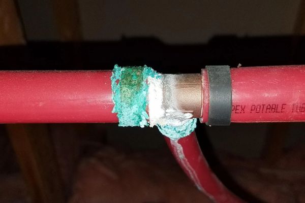
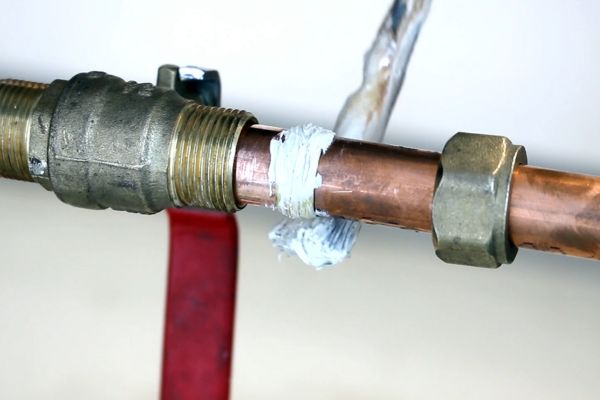
Leaks:
One of the most immediate and apparent consequences of incorrect tube fitting installation is the potential for leaks. A poorly installed fitting may not create a proper seal, allowing fluid to escape. Leaks can lead to a loss of system pressure, reduced efficiency, and increased operating costs due to the need for frequent fluid top-ups. In critical systems, leaks can result in the contamination of the working environment, posing safety risks and potentially damaging other components within the system.
System Failures:
Improper installation can lead to partial or complete system failures. For example, if a tube is not inserted to the correct depth or if fittings are over-tightened, the tube may become detached under pressure, leading to a catastrophic failure. Such failures can cause downtime, disrupt production processes, and result in costly repairs. In some cases, the failure of a single fitting can compromise the entire system, requiring extensive troubleshooting and replacement of parts.
Safety Hazards:
The risks associated with incorrect installation are not limited to mechanical issues; they also include significant safety hazards. Leaking fluids can create slippery surfaces, increasing the risk of slips and falls. In systems carrying hazardous or high-pressure fluids, a fitting failure could lead to exposure to dangerous substances or high-pressure jets, posing serious injury risks to personnel. Additionally, in environments where the fluid is flammable, leaks can create fire hazards, with potentially devastating consequences.
Benefits of Correct Installation
Conversely, when tube fittings are installed correctly, the benefits extend far beyond just avoiding the negative consequences mentioned above. Proper installation ensures that the system operates at its best, providing reliability, safety, and efficiency. Here’s how:
Longevity of the System:
Properly installed tube fittings contribute to the overall longevity of the hydraulic or pneumatic system. By ensuring a secure and accurate fit, the potential for wear and tear on components is minimized, reducing the likelihood of early failure. This, in turn, prolongs the service life of the system, resulting in fewer breakdowns, less frequent maintenance, and ultimately lower total cost of ownership.
Enhanced Performance and Reliability:
A system with correctly installed tube fittings operates more efficiently and reliably. The absence of leaks and the correct alignment of components ensure that the system maintains optimal pressure and flow rates, which are critical for performance. Reliable fittings mean that the system can consistently deliver the required outputs without unexpected interruptions, leading to improved productivity and reduced downtime.
Increased Safety:
Safety is paramount in any industrial setting, and proper installation of tube fittings plays a critical role in ensuring a safe working environment. By following correct installation procedures, the risks of leaks, bursts, and other failures that could endanger personnel are significantly reduced. This not only protects workers from harm but also helps to maintain compliance with safety regulations, avoiding potential fines and legal issues.
Common Errors in Tube Fitting Installation
Proper tube fitting installation is crucial to ensure the efficiency, reliability, and safety of a system. However, several common errors can occur during installation, each with the potential to compromise the entire system. Below is an expanded discussion on these common errors and how to avoid them.
Improper Tube Preparation
Importance of Cleaning:
Contaminant Risks: Before installation, it’s essential to clean the tubes thoroughly. Residues like dirt, oil, and metal shavings can become trapped in the fitting, leading to blockages or contamination of the fluid within the system. These contaminants can cause wear and tear on components, reduce system efficiency, and even lead to failures.
Cleaning Best Practices: Tubes should be cleaned with appropriate solvents or solutions that can remove oils and debris without leaving any harmful residues. Compressed air can also be used to blow out any loose particles from inside the tube.
Risks of Improper Cutting:
Uneven or Jagged Cuts: Cutting the tube improperly can result in uneven or jagged edges, which do not fit snugly into the fitting. This improper fit can lead to leaks or misalignment in the system, which compromises the overall integrity.
Best Practices for Tube Cutting: To achieve a clean, straight cut, use a tube cutter specifically designed for the material you’re working with. Avoid using hacksaws or other tools that can create rough edges. Ensure that the cutting tool is sharp and in good condition to produce smooth cuts.
The Need for Deburring:
Consequences of Leaving Burrs: After cutting, the tube often has burrs or sharp edges that can damage the fitting or create obstacles for proper insertion. Burrs can scratch the fitting surface, leading to improper sealing and potential leaks.
Steps for Proper Deburring: Always use a deburring tool to remove any burrs from the inside and outside edges of the cut tube. This process smoothens the edges, ensuring a better fit and reducing the risk of damage during installation.
Incorrect Tube Insertion Depth
Risks of Shallow Insertion:
Inadequate Engagement: If the tube is not inserted deeply enough into the fitting, it may not engage correctly with the sealing surface, leading to leaks. Shallow insertion can also cause the tube to dislodge under pressure, resulting in system failure.
Ensuring Proper Insertion Depth: Measure the insertion depth using the fitting manufacturer’s guidelines, and mark the tube to ensure it is inserted to the correct depth. It is crucial to follow the specifications to avoid under-insertion.
Over-Insertion:
System Stress and Failures: Conversely, inserting the tube too deeply can cause stress on the system. Over-insertion may lead to excessive pressure on the fitting, causing deformation or cracking over time. This stress can also lead to issues with fluid flow, as the tube may block or restrict pathways within the fitting.
Techniques to Measure and Achieve Correct Insertion Depth: To avoid over-insertion, follow the manufacturer’s specifications precisely. Marking the tube with the appropriate insertion depth before fitting can help ensure accuracy.
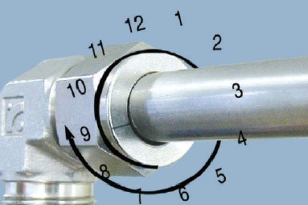
Over-tightening or Under-Tightening Fittings
Impact of Over-Tightening:
Risks of Damage: Over-tightening fittings can cause the threads to strip or the fitting itself to crack. This damage weakens the connection and can lead to leaks, fitting failure, or even catastrophic system breakdowns. Over-tightening can also compress the tube excessively, potentially distorting it and compromising the seal.
Signs of Over-Tightening: Visible signs of over-tightening include distorted threads, cracked fittings, and deformed tubes. It’s crucial to stop tightening as soon as resistance is felt and the fitting is securely in place.
Impact of Under-Tightening:
Potential for Leaks: On the other hand, under-tightening leaves the fitting too loose, which can result in leaks due to an insufficient seal. A loose fitting may also allow the tube to move within the connection, leading to wear and eventual failure.
Guidelines for Achieving the Correct Torque: Use a torque wrench to apply the manufacturer-recommended torque to the fitting. This ensures that the fitting is neither too tight nor too loose. Refer to the fitting manufacturer’s torque specifications and adhere to them precisely.
Using the Wrong Tools
Common Tool-Related Mistakes:
Inappropriate Tools: Using the wrong tools during installation is a common mistake that can lead to improper connections. For instance, using pliers instead of a dedicated tube fitting wrench can cause deformation of the fitting or tube, leading to poor sealing and potential leaks.
Tool Condition: Even the correct tool can cause problems if it is in poor condition, such as a dull cutter or a damaged wrench. Tools that are not well-maintained can damage the fitting or the tube during installation.
Proper Tool Selection and Usage:
Recommended Tools for Installation: Always use the tools specified by the fitting manufacturer. These may include tube cutters, deburring tools, and torque wrenches, among others. The correct tools ensure that the tube is prepared and installed properly without causing damage.
Advanced Considerations in Tube Fitting Installation
Beyond the basic installation practices, there are advanced considerations that are crucial to the long-term success and reliability of tube fitting installations. These considerations include material compatibility and the influence of environmental and operating conditions. Addressing these factors during installation can prevent serious issues down the line and ensure the system performs optimally under all conditions.
Material Compatibility
Importance of Material Compatibility
Matching Materials for Optimal Performance: The materials used in both the tube and fitting must be compatible to ensure proper function and longevity. Incompatible materials can lead to a variety of issues, including weakened connections, leaks, or premature failure of the components. For example, using a fitting made of a different metal than the tube can create problems, particularly in environments where corrosion is a concern.
Preventing Material Degradation: Different materials react differently when exposed to various fluids, temperatures, and environmental conditions. For instance, certain metals may corrode when exposed to specific chemicals or in humid environments, which can lead to the degradation of the tube or fitting. Selecting materials that are resistant to the fluids being transported and to the environmental conditions they will face is essential.
How to Avoid Galvanic Corrosion
Understanding Galvanic Corrosion: Galvanic corrosion occurs when two dissimilar metals come into contact in the presence of an electrolyte, such as water. This electrochemical reaction causes one metal to corrode faster than it would on its own, which can severely weaken the fitting and tube, leading to failure.
Best Practices for Preventing Galvanic Corrosion
Material Selection: Whenever possible, use fittings and tubes made of the same or compatible materials. For example, pairing stainless steel fittings with stainless steel tubes can minimize the risk of galvanic corrosion.
Isolation Techniques: If dissimilar metals must be used, consider using isolating materials, such as non-conductive coatings or gaskets, to prevent direct metal-to-metal contact. This can help to interrupt the electrochemical process that leads to corrosion.
Environmental Control: Control the environment around the fittings to reduce exposure to electrolytes. For instance, keeping fittings dry and avoiding exposure to saltwater or other conductive fluids can help prevent corrosion.
Environmental and Operating Conditions
Addressing Temperature Concerns
Effects of Temperature Extremes on Tube Fittings: Temperature plays a critical role in the performance of tube fittings. Extreme temperatures—whether high or low—can affect the materials used in both tubes and fittings. High temperatures may cause materials to expand, potentially leading to leaks or even fitting failure. On the other hand, low temperatures can cause materials to become brittle, making them more prone to cracking.
Ensuring Fittings Are Suitable for the Operating Environment: It’s essential to choose fittings made from materials that can withstand the expected temperature ranges of the system. For high-temperature applications, materials like stainless steel or specialized alloys may be required. For low-temperature environments, materials that retain their flexibility and strength at lower temperatures should be selected. Always refer to the manufacturer’s specifications for temperature ratings.
Pressure Requirements
How Incorrect Pressure Ratings Can Lead to System Failure: Each tube fitting is designed to withstand a specific pressure range. Installing a fitting that cannot handle the system’s operating pressure can lead to leaks, bursts, and catastrophic system failures. Over-pressurization can cause fittings to crack or deform, leading to immediate or gradual failure.
Guidelines for Matching Fittings with System Pressure:
Pressure Rating Verification: Always verify that the pressure rating of the fitting matches or exceeds the maximum pressure of the system. This includes considering both static and dynamic pressures, as well as potential pressure surges.
Testing Under Operating Conditions: Conduct pressure testing under actual operating conditions to ensure that the fittings can handle the system’s pressure without issues. This step can identify potential weaknesses before the system is fully operational.
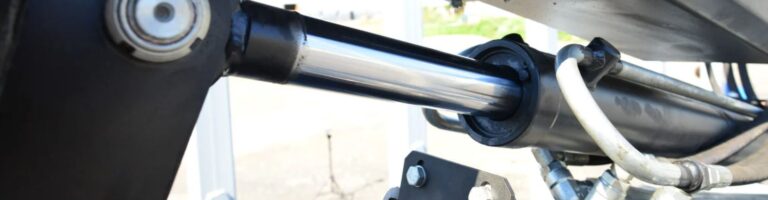
Vibration and Movement
Risks Associated with Vibration and Dynamic Movement: In many industrial applications, systems are subject to constant vibrations or movement, which can place additional stress on tube fittings. Vibration can cause fittings to loosen over time, leading to leaks. Additionally, continuous movement, such as that found in mobile or rotating machinery, can cause wear and fatigue in both tubes and fittings.
Techniques to Mitigate Vibration-Related Issues
Vibration-Resistant Fittings: Use fittings specifically designed to resist the effects of vibration. These fittings may include features such as additional locking mechanisms or flexible connections that can absorb some of the movement.
Support and Securement: Ensure that tubes and fittings are properly supported and secured to minimize movement. This may involve the use of clamps, braces, or other support structures that hold the tube in place and reduce the transfer of vibration to the fitting.
Conclusion
As you move forward with your installations, remember that the foundation of a robust and reliable system lies in meticulous attention to every aspect of the installation process. If you ever need further guidance or expertise, don’t hesitate to consult with professionals who can help ensure that your tube fittings are installed to the highest standards.
FAQ
Cleaning tubes removes contaminants that could cause blockages or corrosion, ensuring a proper seal and preventing leaks.
Mark the tube according to the manufacturer’s guidelines and check that it is inserted fully into the fitting to the marked depth.
Over-tightening can damage the fitting or tube, leading to leaks or fitting failure. Use a torque wrench to apply the correct torque.
Use the tools recommended by the manufacturer, such as a tube cutter, deburring tool, and torque wrench, to ensure proper installation.
Use materials that are compatible, or apply insulating materials between dissimilar metals to prevent corrosion.
Regularly inspect fittings, especially in high-vibration environments, to check for wear, loosening, or leaks, and tighten or replace as necessary.


