Hydraulic hose twisting occurs when a hose rotates along its axis, causing the hose to take on a spiral or corkscrew shape. This can happen during installation, operation, or maintenance, and it often results from improper handling, incorrect installation practices, or external forces acting on the hose. Twisting can lead to a range of problems, including increased stress on the hose, which may compromise its structural integrity.
Understanding Hydraulic Hose Twisting
A. What is Hydraulic Hose Twisting?
Hydraulic hose twisting refers to the rotational movement of a hose along its longitudinal axis, leading to a spiraled or distorted appearance. This twisting often results from either intentional or unintentional actions during the hose’s installation, operation, or maintenance phases. When a hose twists, its internal reinforcement layers become misaligned, which compromises the hose’s ability to withstand pressure and function effectively.
The basic mechanics of hose twisting involve external forces or incorrect installation practices that cause the hose to rotate. This rotation changes the hose’s internal structure, leading to uneven distribution of stress across the hose walls. Over time, this can lead to wear, abrasion, and eventual failure.
Common scenarios where hose twisting occurs:
Improper Tightening Sequence
- When the hose is tightened at both ends without allowing one end to rotate freely, torsional stress builds up.
- This often happens when installers secure fittings with tools while the hose is under tension.
- Always allow one fitting to rotate naturally during tightening.
Forced Hose Routing
- Bending the hose into position without letting it take its natural path can twist the core.
- If the hose appears to “spring back” after routing, torsion may already exist.
- Avoid forcing the hose to meet connection points that don’t align properly.
Over-Tension or Preloading
- Stretching a hose too tightly during installation can introduce hidden torsion.
- A preloaded hose may seem neat but reacts poorly once pressurized.
- Always leave enough slack for movement and pressure expansion.
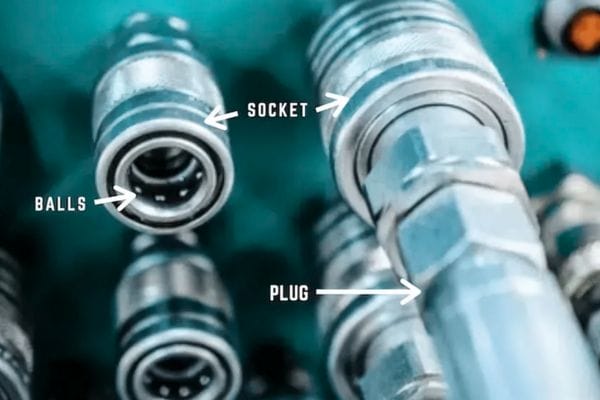
No Use of Swivel Fittings
- Systems with frequent rotation or movement need swivel joints.
- Without swivels, movement at the cylinder or boom transfers directly into the hose as twist.
- Install live swivels or rotating couplers where motion is expected.

B. Causes of Hose Twisting
Improper Installation and Routing:
- Incorrect Alignment: When hoses are installed with a twist or without ensuring proper alignment, twisting is likely to occur. This can happen if the hose is forced into a position where it naturally resists, resulting in a twist.
- Poor Routing Practices: Routing hoses through complex paths without sufficient support can cause them to twist, especially if they are bent or curved excessively.
Inadequate Hose Length or Improper Hose Selection:
- Incorrect Hose Length: If a hose is too long or too short, it may not lay properly along its path, leading to twisting. An improperly sized hose might also be forced to fit, resulting in twists.
- Wrong Hose Type: Selecting a hose that is not suitable for the application or the environment can increase the risk of twisting. For example, a hose without anti-twist features used in a high-movement application might twist more easily.
Excessive Pressure or Movement Within the System:
- Pressure Fluctuations: Sudden changes in pressure can cause hoses to move or twist, particularly in systems that experience high-pressure cycles or shocks.
- System Dynamics: In systems where hoses are subject to frequent movement or flexing, such as in mobile hydraulic equipment, twisting can occur if the hoses are not properly secured or if they are subjected to torsional forces.
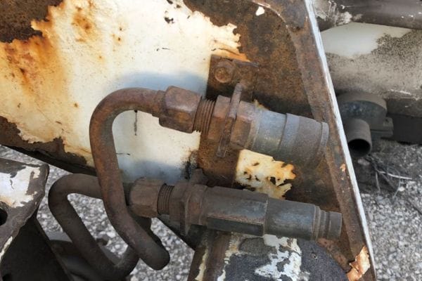
Environmental Factors such as Vibration and Thermal Expansion:
- Vibration: In environments where machinery vibrates continuously, hoses can gradually twist if they are not adequately clamped or supported. Vibration can also loosen fittings, which may contribute to twisting.
- Thermal Expansion: Temperature changes can cause hoses to expand and contract, which, without proper allowances, can lead to twisting over time.
C. Identifying Signs of Twisting
Visual Indicators of Hose Twisting:
- Spiral Appearance: One of the most apparent signs of hose twisting is a spiral or corkscrew-like appearance along the hose’s length. This indicates that the hose has rotated on its axis.
- Kinks and Bends: Twisted hoses often develop sharp kinks or unnatural bends, especially near the fittings. These kinks can lead to restricted fluid flow and potential damage to the hose.
- Displaced Fittings: If a hose appears misaligned with its fittings, or if the fittings are rotated out of their intended orientation, it may be a sign that the hose is twisted.
Symptoms of System Inefficiency Due to Hose Twisting:
- Reduced System Performance: Twisted hoses can restrict fluid flow, leading to a drop in system pressure and overall performance. This can manifest as slower machine operation or a decrease in hydraulic power.
- Increased Operating Temperatures: A twisted hose can create friction within the system, causing components to overheat. This can lead to inefficiencies and increased wear on the system.
- Frequent Maintenance Issues: Systems with twisted hoses often experience more frequent maintenance problems, including leaks, hose ruptures, and fitting failures, all of which contribute to higher operational costs and downtime.
The Consequences of Hydraulic Hose Twisting
A. Impact on Hose Life
How Twisting Reduces Hose Durability:
Hydraulic hoses are designed to withstand significant internal pressure and external forces, but twisting disrupts their structural integrity. When a hose twists, its internal reinforcement layers—typically made of wire braids or spiral-wound materials—become misaligned. This misalignment causes the hose to lose its ability to evenly distribute the forces acting upon it, leading to localized stress points. These stress points weaken the hose, making it more susceptible to damage from pressure fluctuations, abrasion, and external impacts.
Increased Wear and Tear Leading to Premature Failure:
Twisted hoses are subjected to abnormal friction and strain, particularly at the points where the twist is most severe. This leads to accelerated wear and tear, especially along the outer cover and the reinforcement layers. Over time, the hose material becomes fatigued, and small cracks or abrasions can develop, further compromising the hose’s strength. As the hose continues to operate under these conditions, the likelihood of a sudden and catastrophic failure—such as a burst or rupture—increases significantly. This premature failure not only shortens the hose’s service life but also escalates the risk of unexpected system downtime and costly repairs.
B. System Performance Issues
Loss of Efficiency and Potential Safety Hazards:
A twisted hydraulic hose impairs the flow of hydraulic fluid, which is critical for maintaining system efficiency. The internal restriction caused by twisting can lead to a drop in fluid pressure, resulting in sluggish or inconsistent system performance. This inefficiency can manifest in various ways, such as reduced speed of actuators, lower lifting capacities, or erratic operation of hydraulic machinery. In some cases, the reduced flow may cause cavitation, leading to further damage within the system components.
Beyond inefficiency, twisted hoses pose significant safety hazards. The compromised hose is at greater risk of bursting under high pressure, which can lead to sudden and uncontrolled movements of hydraulic machinery. This can endanger both equipment and operators, creating a hazardous work environment.
Increased Maintenance Costs and Downtime:
The consequences of hydraulic hose twisting extend to increased operational costs. The frequent need for hose replacements, coupled with the potential for associated damage to other system components, drives up maintenance expenses. Moreover, the time required to identify, troubleshoot, and resolve issues related to twisted hoses contributes to unscheduled downtime, which can severely impact productivity, particularly in industries where continuous operation is critical.
In the long run, the cumulative costs of repeated hose failures, system inefficiencies, and downtime can significantly affect a company’s bottom line, making proactive management of hose twisting an essential aspect of hydraulic system maintenance.
C. Potential Safety Risks
Hose Rupture and Leakage Risks:
One of the most severe consequences of hydraulic hose twisting is the increased risk of hose rupture. As twisting intensifies the stress on the hose material, it becomes more vulnerable to sudden failures. A ruptured hose can release hydraulic fluid at high pressure, creating a dangerous situation for anyone nearby. The sudden release of fluid can cause equipment to lose control, potentially leading to accidents or injuries.
Even if a complete rupture does not occur, twisting can cause small leaks at the fittings or along the hose length. These leaks not only reduce system efficiency but also create slip hazards, contribute to environmental contamination, and can lead to more significant system failures if left unaddressed.
Environmental Hazards Due to Hydraulic Fluid Spills:
Hydraulic fluid spills are a serious environmental concern, particularly in industries operating in sensitive or regulated environments. A twisted hose that fails can release large quantities of hydraulic fluid, contaminating soil, water sources, and nearby vegetation. Cleanup efforts can be costly and time-consuming, and in some cases, companies may face fines or penalties for environmental violations.
Additionally, hydraulic fluids are often toxic, and their release can pose health risks to workers who may come into contact with the spilled fluid. Proper management of hose twisting, therefore, not only protects equipment and personnel but also helps mitigate environmental risks and ensure compliance with environmental regulations.
Best Practices for Preventing Hose Twisting
A. Proper Hose Installation Techniques
Ensuring Correct Hose Length and Routing:
Selecting the correct hose length is fundamental in preventing twisting. A hose that is too long or too short can cause alignment issues, leading to unnecessary stress and potential twisting. Proper measurement and allowance for movement and flexibility are key. The hose should be long enough to accommodate movement but not so long that it sags or loops excessively.
Correct routing is also crucial. Hoses should be routed in a way that avoids sharp bends, kinks, or excessive tension. It is important to follow the natural curvature of the hose and ensure that it is not forced into unnatural positions during installation. Routing hoses away from sources of vibration, heat, and sharp edges will further help to prevent twisting.
Importance of Following Manufacturer Guidelines:
Each hydraulic hose comes with specific manufacturer guidelines that must be adhered to during installation. These guidelines provide essential information on the correct installation techniques, recommended routing practices, and the operational limits of the hose. Ignoring these guidelines can lead to improper installation, which is a primary cause of hose twisting.
Manufacturer guidelines often include instructions on how to avoid twisting during installation. For instance, they may recommend pre-positioning the hose ends before tightening the fittings to ensure that the hose is not twisted during assembly. Adhering to these guidelines ensures that the hose is installed correctly and reduces the risk of twisting during operation.
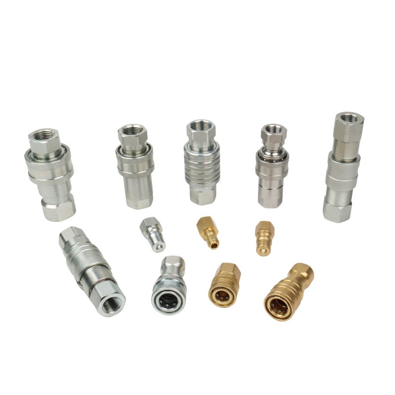
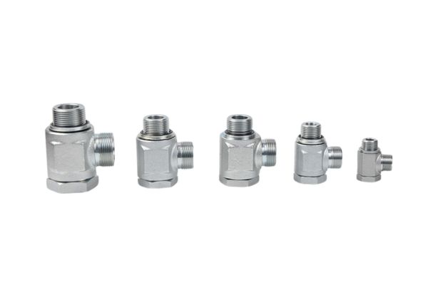
Use of Swivel Fittings to Reduce Twisting Stress:
Swivel fittings are a valuable tool in preventing hose twisting, especially in systems where hoses are subject to frequent movement. These fittings allow the hose to rotate freely, absorbing rotational forces that would otherwise cause the hose to twist.
Incorporating swivel fittings at strategic points in the hydraulic system can significantly reduce the stress on the hose, thereby extending its lifespan and maintaining system efficiency. Swivel fittings are particularly useful in applications where the hose is connected to moving parts or where there is a high degree of system vibration.
Need custom configurations? We offer swivel solutions with your thread type, pressure rating, or coating preferences. Contact us to get drawings or samples tailored to your system.
Use of Marker Lines
Marker lines are a simple but effective way to detect hose twisting during and after installation.
How It Works
- During installation, align the marker line so it remains straight.
- After routing the hose, inspect the line:
- If it curves or spirals, the hose has been twisted.
- A clean, straight line means the hose is properly installed.
When to Use It
- Always apply or check the marker line before final tightening of both ends.
- Especially important in complex systems with multiple bends or hard-to-reach fittings.
- Ideal for field service checks—quick visual inspection without disassembly.
Installation Tip
- If twisting is detected, release one end, let the hose relax, and reinstall with correct orientation.
- Use the marker line again after pressurizing the system to ensure no torsion was introduced during clamping.

B. Selection of Appropriate Hose and Fittings
Choosing Hoses with Anti-Twist Properties:
Some hoses are specifically designed with anti-twist features. These hoses have reinforced layers or construction techniques that resist twisting, making them ideal for applications where twisting is a concern. When selecting a hose, consider the specific requirements of your application and whether an anti-twist hose would be beneficial.
Anti-twist hoses are particularly useful in dynamic systems where the hose is subjected to frequent movement or where the hose routing is complex and may introduce rotational forces.
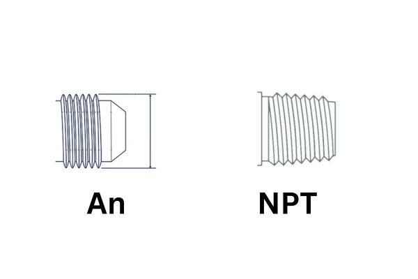
Importance of Matching Fittings and Hoses Correctly:
The compatibility between the hose and its fittings is crucial to preventing twisting. Mismatched fittings can lead to improper installation, causing the hose to twist or become damaged over time. It is essential to ensure that the fittings are appropriately sized and compatible with the hose material and type.
Using high-quality fittings that are specifically designed for the hose in use will help ensure a secure, twist-free connection. This also includes considering the type of threads and connectors used, as improper threading can introduce twisting forces during assembly.
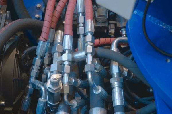
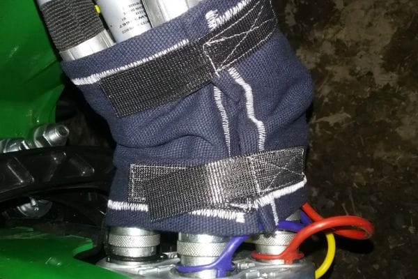
C. Use of Hose Clamps and Guides
Strategic Placement of Clamps and Guides to Prevent Twisting:
Hose clamps and guides are essential for securing hoses and preventing twisting, especially in environments where hoses are subject to movement. Properly placed clamps can hold the hose in position, preventing it from rotating or shifting during operation.
Clamps should be positioned at intervals along the hose’s length, particularly near bends and connection points, to ensure that the hose remains securely in place. The use of hose guides, which direct the hose along a specific path, can further help prevent twisting by maintaining the hose’s intended routing.
Best Practices for Securing Hoses in Dynamic Environments:
In dynamic environments where hoses are exposed to movement, vibration, or thermal expansion, additional precautions should be taken to secure them. This includes using flexible clamps or brackets that allow some movement without causing the hose to twist or become damaged.
It is also important to regularly check the condition of clamps and guides to ensure they are not loose or worn, as these can become sources of twisting if they fail. In applications where movement is significant, consider using dampeners or vibration isolators to reduce the forces acting on the hose.
D. Regular Inspection and Maintenance
Routine Checks for Signs of Twisting and Wear:
Regular inspection of hydraulic hoses is essential for identifying early signs of twisting and wear. During routine checks, look for visual indicators such as spiraling, kinks, or misaligned fittings. Early detection of these signs allows for corrective action before more severe damage occurs.
Inspect the hose at regular intervals based on the system’s operational conditions, frequency of use, and the manufacturer’s recommendations. Include checks for wear, abrasion, and any signs of leakage, which could indicate a twisted or damaged hose.
Preventive Maintenance Schedules to Avoid Issues:
Implementing a preventive maintenance schedule is crucial to avoiding hose twisting and ensuring the longevity of the hydraulic system. This schedule should include regular inspections, as well as planned hose replacements before they reach the end of their service life.
Preventive maintenance helps to identify potential issues before they become major problems, reducing the risk of unexpected downtime and costly repairs. It also ensures that hoses are always in optimal condition, minimizing the risk of twisting and related failures.
Importance of Replacing Damaged or Twisted Hoses Promptly:
If a hose is found to be twisted or damaged during inspection, it should be replaced immediately. Continuing to use a compromised hose increases the risk of catastrophic failure, which can lead to system damage, environmental hazards, and safety risks.
Prompt replacement of damaged hoses not only protects the hydraulic system but also ensures continued operational efficiency and safety. Always use the correct replacement hose and fittings as per the manufacturer’s specifications to avoid introducing new risks.
Conclusion
Preventing hydraulic hose twisting is not just about following a set of guidelines; it’s about committing to a culture of proactive maintenance and attention to detail. By implementing the best practices discussed, such as ensuring proper hose installation, selecting the right hoses and fittings, and maintaining a rigorous inspection schedule, companies can prevent the costly and dangerous consequences of hose twisting.
Topa offers a wide range of swivel adapters, anti-twist hose assemblies, and routing services to help you eliminate twisting risks. Need a custom anti-twist solution? Contact our team or request a catalog today!
FAQ
What causes hydraulic hose twisting?
Hydraulic hose twisting can be caused by improper installation, incorrect hose routing, inadequate hose length, or environmental factors like vibration and thermal expansion.
How can I prevent hydraulic hose twisting during installation?
To prevent twisting, ensure the hose is properly aligned, use swivel fittings, follow manufacturer guidelines, and avoid forcing the hose into unnatural positions.
What are the signs that a hydraulic hose is twisted?
Common signs include a spiral or corkscrew appearance, kinks, misaligned fittings, and reduced system performance.
Why is hydraulic hose twisting dangerous?
Twisting weakens the hose, increasing the risk of rupture, leaks, and system failure, which can lead to safety hazards and environmental damage.
Can twisted hoses be fixed, or do they need to be replaced?
Twisted hoses typically need to be replaced, as the internal damage caused by twisting cannot be easily repaired.
What maintenance practices help prevent hose twisting?
Regular inspections, proper hose routing, the use of clamps and guides, and following a preventive maintenance schedule can help prevent hose twisting.