Extreme heat poses a significant threat to hydraulic hose performance. Elevated temperatures can lead to a range of detrimental effects, including material degradation, loss of flexibility, and compromised structural integrity. As temperatures rise, the risk of hose failure increases, which can result in leaks, system malfunctions, and even catastrophic accidents. Understanding how heat impacts hydraulic hoses is critical for industry professionals tasked with maintaining equipment and ensuring uninterrupted operations.
Understanding Hydraulic Hoses
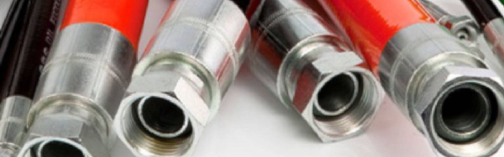
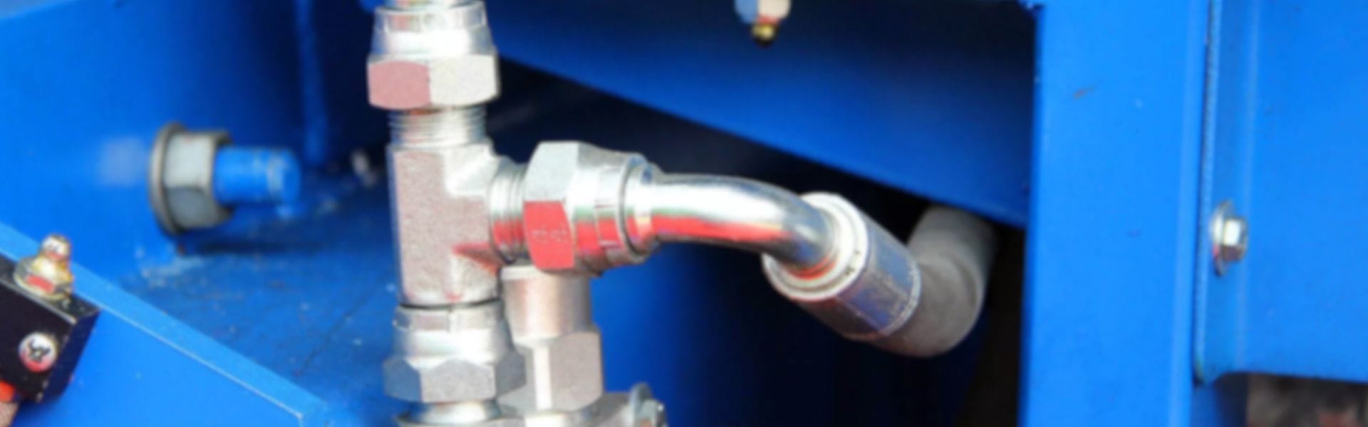
Hydraulic hoses are essential components in hydraulic systems, designed to transmit fluid under high pressure. Their performance and reliability are critical for the safe and efficient operation of various machinery. Understanding the different types of hydraulic hoses, their construction, and specifications is vital for making informed choices in industrial applications.

Types of Hydraulic Hoses and Their Applications
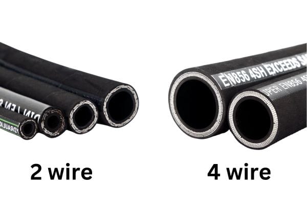
Wire-Reinforced Hoses:
Description: These hoses feature one or more layers of steel wire, providing enhanced strength and flexibility.
Applications: Commonly used in high-pressure applications, such as construction equipment and agricultural machinery.
Textile-Reinforced Hoses:
Description: Constructed with synthetic fibers, these hoses are lightweight and flexible but less robust than wire-reinforced options.
Applications: Ideal for low to medium-pressure applications, such as in service stations and automotive systems.
Thermoplastic Hoses:
Description: Made from synthetic materials, these hoses are resistant to abrasion and chemicals.
Applications: Frequently used in industries that require flexibility and a range of operating temperatures, such as robotics and mobile equipment.
Specialized Hoses:
Description: These hoses are tailored for specific functions, such as high-temperature or high-chemical resistance.
Applications: Used in demanding environments, including oil and gas, aerospace, and food processing.
Key Components and Materials Used in Hydraulic Hose Construction
Hydraulic hoses are typically composed of three main layers:
Inner Tube:
Material: Usually made from rubber or thermoplastic elastomers, the inner tube is responsible for containing the hydraulic fluid.
Properties: Must be resistant to the fluid it carries and withstand high pressure.
Reinforcement Layer:
Material: Composed of textile or steel wire, this layer adds strength and durability.
Properties: Determines the hose’s pressure rating and flexibility.
Outer Cover:
Material: Made from abrasion-resistant materials like rubber or polyurethane.
Properties: Protects the hose from environmental factors, such as UV exposure, ozone, and chemicals.
Importance of Temperature Ratings and Specifications
Temperature ratings are critical for ensuring the safe operation of hydraulic hoses. Each hose is designed to withstand specific temperature ranges, which are outlined in its specifications. Operating a hose outside of these ratings can lead to premature failure, leaks, and system downtime.
High-Temperature Ratings: Some hoses are engineered to operate in extreme heat, making them suitable for applications in high-temperature environments.
Low-Temperature Ratings: Conversely, hoses that are designed for low temperatures ensure flexibility and integrity in colder conditions.
Understanding and adhering to these temperature specifications is vital for selecting the right hydraulic hose for an application. Failure to do so can result in costly repairs and safety hazards.
The Science of Heat
Understanding heat and temperature is essential for comprehending how extreme heat impacts hydraulic hoses. Temperature measures the average kinetic energy of particles in a substance, while heat refers to the energy transferred between substances due to a temperature difference. In hydraulic systems, managing this heat is crucial for maintaining optimal performance and preventing damage.
Heat Transfer Mechanisms
Heat transfer occurs through three primary mechanisms: conduction, convection, and radiation.
Conduction: This is the transfer of heat through direct contact between materials. In hydraulic hoses, heat can be conducted from hot fluids to the hose material, raising its temperature.
Convection: In hydraulic systems, convection occurs when fluids circulate and transfer heat away from or toward components, including hoses. Proper fluid flow can help dissipate heat, while stagnant conditions can lead to overheating.
Radiation: This involves the emission of heat energy as electromagnetic waves. In hydraulic systems, radiation may be less significant but can still contribute to overall heat exposure, especially in high-temperature environments.
Molecular Effects of Heat
When exposed to elevated temperatures, materials change at a molecular level. Increased heat energy causes molecules to vibrate more rapidly, leading to several potential consequences:
Thermal Expansion: Most materials expand when heated, which can alter the dimensions of hydraulic hoses and fittings, potentially leading to misalignment and increased stress on connections.
Material Degradation: Heat can weaken the chemical bonds within materials. For rubber and thermoplastic hoses, this can lead to hardening, cracking, and loss of elasticity, ultimately compromising their integrity.
Chemical Reactions: Elevated temperatures can accelerate chemical reactions, such as oxidation or hydrolysis, particularly in rubber hoses. These reactions can deteriorate the material, resulting in leaks and failures.

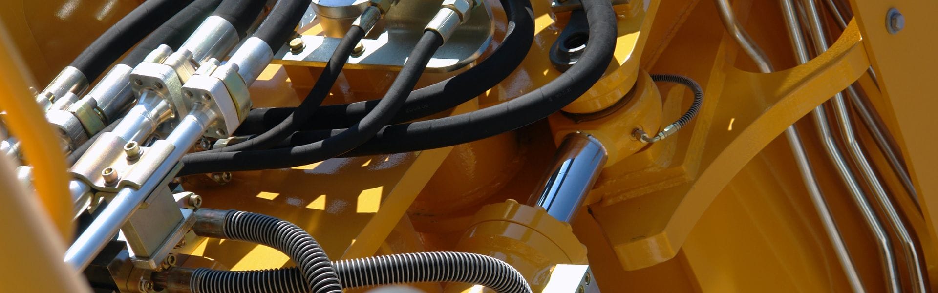
Common Sources of Extreme Heat in Hydraulic Systems
Identifying the sources of extreme heat in hydraulic systems is essential for effective management. Common sources include:
High Fluid Temperatures: Fluid temperature can rise due to excessive work, leading to increased friction within the system. Components like pumps and motors generate heat, contributing to the overall temperature of the hydraulic fluid.
Environmental Factors: Operating in hot environments, such as deserts or industrial settings with high ambient temperatures, can significantly elevate the temperature of hydraulic hoses.
Inadequate Cooling: Systems without proper cooling mechanisms, such as heat exchangers or radiators, may fail to dissipate heat effectively, leading to overheating.
Overloading: Operating equipment beyond its rated capacity increases the workload on hydraulic components, generating excessive heat.
Effects of Extreme Heat on Hydraulic Hoses
Extreme heat can have detrimental effects on hydraulic hoses, significantly affecting their material properties, performance, and longevity. Understanding these effects is crucial for maintaining hydraulic systems and preventing costly failures.
Deterioration of Materials
Hydraulic hoses are typically constructed from materials such as rubber, thermoplastics, and synthetic compounds, each of which reacts differently to heat.
Rubber Hoses:
Degradation: Rubber is particularly sensitive to heat. Elevated temperatures can lead to oxidation, causing the material to harden and lose elasticity. This degradation can manifest as cracks, surface blistering, and increased brittleness.
Chemical Composition Changes: Heat can also alter the chemical structure of rubber, diminishing its resistance to fluids and making it more susceptible to leaks.
Thermoplastic Hoses:
Softening: Thermoplastics, while often more resistant to chemicals, can soften under extreme heat. This softening can lead to deformation and failure to maintain shape, affecting the hose’s integrity and performance.
Environmental Stress Cracking: Prolonged exposure to high temperatures can exacerbate environmental stress cracking, particularly in applications involving aggressive fluids.
Synthetic Compounds:
Performance Loss: Synthetic materials may be engineered for specific applications, but excessive heat can still compromise their properties. This can lead to a reduction in tensile strength and overall performance capabilities.
Impact on Flexibility, Strength, and Overall Performance
Extreme heat adversely impacts the flexibility and strength of hydraulic hoses, which are crucial for their functionality.
Loss of Flexibility:
As hoses become brittle from heat exposure, they lose the flexibility needed to withstand bending and movement. This rigidity can lead to kinks and bends that restrict fluid flow, resulting in pressure drops and inefficiencies in hydraulic systems.
Reduction in Strength:
High temperatures can weaken the structural integrity of hoses. The loss of tensile strength makes hoses more prone to ruptures and breaks, especially under pressure. This is particularly critical in applications where high-pressure fluids are involved.
Overall Performance Issues:
The combination of reduced flexibility and strength leads to overall performance degradation. Hydraulic systems may experience decreased efficiency, slower response times, and increased wear on components, leading to more frequent maintenance and potential downtime.
Risk of Leakage and Hose Failure
One of the most significant risks associated with extreme heat is the potential for leakage and catastrophic hose failure.
Leakage:
As materials deteriorate and lose elasticity, seals within hydraulic connections may fail, leading to fluid leaks. This not only compromises system performance but can also pose safety hazards and environmental concerns.
Catastrophic Failure:
In extreme cases, a hose may burst due to excessive heat, resulting in a sudden release of pressurized fluid. This can cause significant damage to surrounding equipment and pose serious risks to operators and personnel.
Safety Concerns:
Leakage and failures in hydraulic systems can lead to hazardous situations, including fire risks, especially in industries dealing with flammable fluids. Preventative measures are essential to mitigate these risks.
Signs of Heat Stress in Hydraulic Hoses
Identifying heat stress in hydraulic hoses is critical for preventing failures and maintaining system efficiency. Recognizing the visual indicators of damage, and performance issues, and employing testing methods can help ensure the longevity and reliability of hydraulic systems.
Visual Indicators of Damage
Cracks and Surface Degradation:
Description: Small cracks may appear on the surface of the hose, particularly when rubber or synthetic materials degrade due to heat exposure. These cracks can eventually expand, compromising the hose’s integrity.
What to Look For: Check for any visible splits or fissures, especially near fittings or bends where stress concentration occurs.
Discoloration:
Description: Color changes often indicate material degradation. For rubber hoses, fading or a brownish tint can suggest overheating.
What to Look For: Inspect the hose for any unusual color changes that could signify a breakdown of the material due to prolonged heat exposure.
Bloating or Bulging:
Description: Heat can cause hoses to expand or bulge, indicating that the internal structure is compromised.
What to Look For: A hose that appears swollen or misshapen should be replaced, as this can lead to failure.

Performance Issues to Watch For
Decreased Efficiency:
Description: Overheating can lead to a reduction in the efficiency of hydraulic systems. As hoses degrade, they may not transmit fluid effectively, causing sluggish operation.
Indicators: Monitor the performance of machinery; any noticeable lag in response time may indicate a hose issue.
Pressure Loss:
Description: A significant sign of hose deterioration is a drop in system pressure. This can occur due to leaks or restricted flow caused by damaged hoses.
Indicators: Regularly check pressure gauges for anomalies. A sudden pressure drop can be an early warning of hose failure.
Increased Operating Temperatures:
Description: If hoses are compromised, the hydraulic fluid may overheat more quickly due to inefficient heat dissipation.
Indicators: Use temperature sensors to monitor fluid temperatures. A rise beyond normal operating levels may indicate hose issues.
Testing Methods to Identify Heat-Related Problems
Visual Inspections:
Procedure: Regularly inspect hoses for visible signs of damage, using a checklist to ensure thorough evaluation.
Frequency: Conduct these inspections during routine maintenance checks or whenever the system is serviced.
Pressure Testing:
Procedure: Apply pressure to the hose beyond normal operating levels to check for leaks or performance drops. This should be done cautiously to avoid damaging the hose further.
Interpretation: If leaks or significant drops in pressure are observed, the hose may be compromised.
Thermal Imaging:
Procedure: Use thermal imaging cameras to detect hot spots along the hose. This technology can identify areas where heat buildup is excessive, suggesting potential failure points.
Benefits: Non-invasive and can quickly reveal problem areas without disrupting system operation.
Ultrasonic Testing:
Procedure: Employ ultrasonic sensors to detect internal flaws within hoses that are not visible externally. This method can identify issues before they manifest as visible damage.
Benefits: Provides a deeper insight into the condition of the hose, especially in high-pressure applications.
Preventative Measures and Solutions
To mitigate the risks associated with extreme heat and extend the lifespan of hydraulic hoses, implementing effective preventative measures is crucial. This section outlines strategies for selecting appropriate hoses, best practices for installation and maintenance, and the use of cooling systems and insulation.
Selecting Heat-Resistant Hydraulic Hoses
Material Selection:
Heat-Resistant Materials: When choosing hydraulic hoses, opt for those made from heat-resistant materials such as fluoropolymers or special blends designed to withstand high temperatures.
Temperature Ratings: Always check the manufacturer’s specifications for maximum operating temperatures. Select hoses that exceed the expected operational range to ensure reliability under heat stress.
Reinforcement Types:
Wire vs. Textile Reinforcement: For high-pressure applications in extreme heat, wire-reinforced hoses are typically more robust than textile-reinforced options, providing better stability and longevity.
Custom Solutions: Consider hoses that offer custom specifications tailored to specific environmental conditions, including heat resistance and flexibility.
Best Practices for Installation and Maintenance
Proper Installation:
Avoiding Bends and Kinks: During installation, ensure that hoses are routed to avoid sharp bends and kinks that can create stress points, leading to heat accumulation and potential failure.
Secure Connections: Ensure that all fittings and connections are secure to prevent leaks, which can lead to heat buildup in localized areas.
Regular Inspections:
Scheduled Check-Ups: Conduct regular inspections to identify early signs of wear, such as discoloration, cracking, or bulging. Establish a routine maintenance schedule to ensure consistent oversight.
Monitoring Operating Conditions: Keep track of operating temperatures and pressures. Use gauges to monitor performance and identify any abnormalities early.
Replacement Protocols:
Timely Replacement: If a hose shows significant wear or damage, replace it promptly to avoid failures that can lead to costly downtime or accidents.
Documenting Hose Lifespan: Maintain records of installation dates and maintenance checks to help predict when hoses may need replacement based on usage and conditions.
Use of Cooling Systems and Insulation
Cooling Systems:
Integration of Cooling Solutions: In high-temperature environments, consider integrating cooling systems such as heat exchangers or liquid cooling solutions. These systems help dissipate heat from hydraulic fluids before they reach critical levels.
Fluid Temperature Management: Regularly monitor the temperature of hydraulic fluids to ensure they remain within acceptable limits, adjusting cooling systems as necessary.
Insulation Techniques:
Insulating Hoses: Use thermal insulation wraps or sleeves around hydraulic hoses to protect them from external heat sources. This can significantly reduce heat transfer and protect hose integrity.
Heat Shields: For hoses that are particularly vulnerable to extreme heat, install heat shields that can reflect and absorb heat, further protecting the hose material.
Environmental Considerations:
Assessing Operating Environment: Evaluate the working environment for potential heat sources, such as nearby machinery or direct sunlight. Implement measures to shield hoses from these influences where possible.
Ventilation: Ensure adequate ventilation in areas where hydraulic systems operate, as proper airflow can help dissipate heat and maintain optimal operating conditions.
Conclusion
We encourage industry professionals to adopt best practices in maintenance, including selecting heat-resistant hoses, adhering to proper installation techniques, and implementing routine inspections. By prioritizing these strategies, businesses can significantly enhance the longevity and reliability of their hydraulic systems, ultimately leading to improved operational efficiency and reduced downtime. Investing in quality hoses and maintenance practices not only safeguards equipment but also contributes to a safer working environment for all personnel involved.
FAQ
What are hydraulic hoses?
Hydraulic hoses are flexible tubes designed to carry hydraulic fluids under pressure in various machinery and equipment.
How does extreme heat affect hydraulic hoses?
Extreme heat can lead to material degradation, loss of flexibility, and increased risk of leaks or hose failure.
How often should I inspect my hydraulic hoses?
Regular inspections should be conducted as part of a routine maintenance schedule, ideally every few months or more frequently in high-stress environments.
How can I prevent heat-related damage to hydraulic hoses?
Select heat-resistant hoses, ensure proper installation, and conduct regular maintenance and inspections.
What materials are best for high-temperature hydraulic hoses?
Hoses made from fluoropolymers or special blends designed for high temperatures are recommended for extreme heat applications.
What are the signs of heat stress in hydraulic hoses?
Common signs include cracks, discoloration, bulging, decreased efficiency, and pressure loss.