Ball Valve Basics banner

Ball Valve Basics: What You Need to Know for Fluid Control

Ball valves are a crucial component in fluid control systems, widely used across various industries to manage the flow of liquids, gases, and other fluids. Known for their durability, reliability, and simple operation, ball valves offer a quick, quarter-turn shutoff mechanism that makes them ideal for applications requiring precise flow control. Their robust design and ability to handle high pressures make them versatile solutions in industries like oil & gas, manufacturing, water treatment, and HVAC systems.

What Is a Ball Valve?

A ball valve is a mechanical device used to regulate, control, and direct the flow of fluids—such as water, gas, or oil—within a pipeline or hydraulic system. The valve gets its name from its spherical component, the “ball,” which features a hollow or solid center that, when rotated, either allows or restricts fluid flow. Ball valves are widely used in industrial, commercial, and residential applications due to their reliability and simple mechanism.

Core Components of a Ball Valve

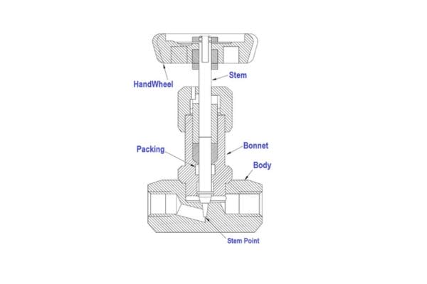
Body: The outer casing that contains all internal components. It is the main structure of the valve and can be made from various materials depending on the application, such as brass, stainless steel, or plastic.

Ball: A spherical component with a hole (bore) in the center. When the ball is rotated 90 degrees, the bore either aligns with the pipe for fluid flow or turns perpendicular to block the flow.

Stem: The shaft that connects the ball to the actuator or handle. It transfers the rotational force from the actuator or manual lever to the ball, enabling the open or close function.

Seats: Sealing components located between the ball and the body, typically made of soft materials like Teflon. These ensure a tight seal to prevent leaks when the valve is closed.

Ball Valve component

How Ball Valves Operate

Ball valves operate with a simple mechanism: when the handle or actuator rotates the stem, it turns the ball inside the valve body. In the open position, the hole in the ball aligns with the pipeline, allowing fluid to pass through freely. In the closed position, the solid side of the ball blocks the passage, stopping the flow completely. This quarter-turn (90-degree rotation) mechanism provides quick and effective operation.

Common Materials Used in Ball Valve Manufacturing

Brass: Ideal for plumbing and low-pressure systems due to its corrosion resistance and cost-effectiveness.

Stainless Steel: Used in industries where high pressure, temperature, or corrosive fluids are involved. Stainless steel offers durability and resistance to extreme conditions.

PVC (Polyvinyl Chloride): Often used in lower-pressure applications like irrigation or residential plumbing, PVC ball valves are lightweight, corrosion-resistant, and cost-effective.

Key Advantages of Ball Valves

Ball valves offer several advantages over other valve types:

Durability: With minimal moving parts and strong construction, ball valves are highly durable and suitable for long-term use.

Quick Operation: The quarter-turn mechanism allows for fast, easy opening and closing.

Versatility: Ball valves can handle high-pressure environments and a wide variety of fluids, making them suitable for diverse industries.

These attributes make ball valves a go-to choice for fluid control systems that require reliable, long-lasting, and efficient performance.

How Ball Valves Work: Operating Principles

Ball valves are known for their simple yet efficient operation, which relies on a 90-degree rotational movement of the ball within the valve body. This quarter-turn mechanism makes ball valves particularly effective for on/off applications, providing both quick operation and a secure seal to prevent leaks.

90-Degree Rotation for Open/Close Functionality

The primary feature of ball valves is their 90-degree rotation mechanism. The ball inside the valve has a hole (or bore) through its center. When the valve handle or actuator is turned 90 degrees, the ball rotates accordingly:

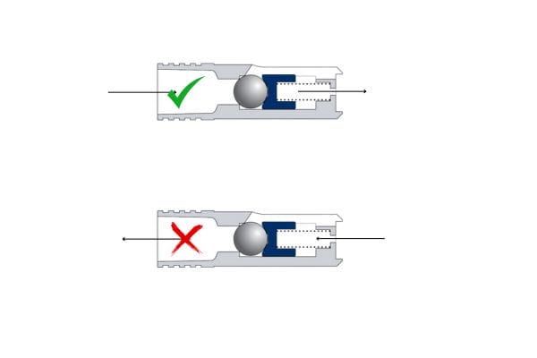
Open Position: When the ball is turned so that the bore aligns with the pipeline, the valve is in the open position, allowing the fluid to flow freely through the valve.

Closed Position: When the ball is rotated 90 degrees from the open position, the solid side of the ball blocks the passage, preventing fluid from flowing through the valve.

This quarter-turn rotation offers a fast, straightforward method to control fluid flow, making ball valves ideal for situations that require quick shutoff or full-flow capacity.

Flow Control Mechanics (Quarter-Turn Mechanism)

Ball valves operate on the principle of a quarter-turn rotation, meaning they require only a 90-degree movement to shift from fully open to fully closed (or vice versa). The actuator or manual handle is connected to the stem, which in turn is connected to the ball. The ball’s bore, when aligned with the pipeline, allows fluid to flow. As the handle is turned, the ball moves into a position where the solid side blocks the passage, thereby stopping the flow.

This quarter-turn design not only provides efficient operation but also helps reduce wear and tear on the valve, especially in high-use environments. The simplicity of the mechanism makes ball valves less prone to mechanical failure compared to other more complex valve types.

Ball Valves uses

Sealing Methods and How Ball Valves Prevent Leaks

One of the key advantages of ball valves is their excellent sealing capabilities. The ball itself doesn’t provide the seal; instead, it is the interaction between the ball and the valve seats that creates a leak-proof system. The seats are typically made of soft materials like Teflon (PTFE), which are resilient enough to compress and form a tight seal against the ball when the valve is closed.

Here’s how ball valves achieve a tight seal:

Seat Compression: The soft seat materials compress around the ball when the valve is in the closed position. This prevents fluid from leaking past the ball.

Stem Seals: In addition to the ball and seats, ball valves also have stem seals to prevent fluid from leaking out around the stem. These seals are typically O-rings or packing that compress around the stem, ensuring no leaks at the actuator interface.

The combination of these seals makes ball valves highly effective at preventing leaks, even in high-pressure systems.

How the Ball’s Position Dictates Flow (Full Open, Partial Open, Full Close)

The ball’s position inside the valve body directly determines the flow rate:

Full Open: In the fully open position, the bore of the ball is aligned with the pipeline, allowing maximum flow. Since the bore’s diameter typically matches the pipe’s, there is minimal pressure drop, making ball valves highly efficient for full-flow applications.

Partial Open: Although ball valves are primarily designed for on/off control, they can be partially opened to allow throttling. However, this is not recommended for long-term flow control as it can lead to wear on the seats and create turbulence within the valve.

Full Close: In the fully closed position, the solid side of the ball blocks the flow entirely. This position provides a secure shutoff, ensuring that no fluid can pass through the valve.

Importance of Pressure Balancing in High-Pressure Systems

In high-pressure systems, balancing the pressure across the valve is crucial for safe and effective operation. If the pressure inside the valve is not properly managed, it can lead to excessive wear on the seats, stem, and other components. For high-pressure applications, a trunnion-mounted ball valve is often preferred because it offers additional support for the ball, reducing the mechanical strain caused by high pressures.

In contrast to floating ball valves (where the ball is supported solely by the seats), trunnion-mounted valves have an additional anchoring point at the base of the ball, ensuring better pressure distribution. This makes them more suitable for systems with higher pressure demands.

Ball Valve Selection Criteria  

A. Material Considerations

The material of a ball valve is critical because it must be compatible with the fluid being controlled. Choosing the right material ensures longevity and reduces the risk of corrosion, degradation, or malfunction. Here are some common considerations:

Corrosion Resistance: For fluids like chemicals, acids, or saline solutions, corrosion resistance is essential. Stainless steel is often chosen for its resistance to harsh chemicals and environments, whereas brass is ideal for less aggressive fluids like water or non-corrosive gases.

Temperature Tolerance: Certain materials are more suited to extreme temperatures. Brass and stainless steel can handle high temperatures, making them ideal for industrial applications, while PVC is more suitable for lower-temperature environments like water distribution systems.

Popular Material Choices:

Brass: Commonly used for water, air, and oil, brass is a cost-effective and corrosion-resistant material, making it suitable for general-purpose applications.

Stainless Steel: This material is favored in industries like chemical processing, pharmaceuticals, and food production due to its excellent resistance to corrosion and high temperatures.

PVC: Often used in residential and light industrial applications, PVC valves are lightweight, affordable, and corrosion-resistant but not suitable for high temperatures or pressures.

Choosing the right material ensures that the valve will function reliably without the risk of corrosion, material degradation, or failure due to temperature extremes.

B. Port Size and Flow Requirements

Port size is another key factor in ball valve selection. There are two primary types of port designs: full-port and reduced port.

Full-Port Ball Valves: Also known as full-bore valves, these valves have an internal diameter that matches the pipe diameter. Full-port designs allow for maximum flow with minimal pressure drop, making them ideal for applications requiring high flow rates or systems where minimizing pressure loss is important, such as in water distribution or fuel systems.

Reduced-Port Ball Valves: Also called standard-port valves, these valves have a smaller internal diameter than the connected pipe. This design reduces the flow rate and can cause a slight pressure drop but is often sufficient for applications where precise control over flow is not essential. Reduced-port valves are typically more affordable and smaller in size, making them suitable for systems where space and budget are considerations.

When selecting between full-port and reduced-port valves, it’s important to assess the specific flow requirements of your system and whether pressure loss is a critical factor.

C. Pressure and Temperature Ratings

Ball valves are designed to handle different pressures and temperatures, and selecting a valve with appropriate ratings is crucial to ensuring safe and efficient operation.

Maximum Operating Pressure: Each ball valve is rated for a specific maximum pressure it can handle. For example, stainless steel ball valves can withstand higher pressures (up to 1000 PSI or more), making them suitable for hydraulic or high-pressure gas systems. In contrast, PVC ball valves are limited to lower pressures (around 150 PSI), making them ideal for low-pressure water applications.

Temperature Ratings: Along with pressure, temperature tolerance is critical. Brass and stainless steel can tolerate higher temperatures, up to 450°F (232°C) and beyond, while PVC has a much lower tolerance, typically maxing out around 140°F (60°C).

To ensure your ball valve can handle the operating conditions, always check the valve’s pressure and temperature ratings and match them to your system’s demands.

D. Connection Types

The way a ball valve connects to a system is important for both installation and long-term use. There are several connection types, each with its pros and cons:

Threaded Connections: These are the most common for residential and light industrial applications. They are easy to install and remove but may require sealing compounds (like Teflon tape) to prevent leaks. Threaded valves can loosen over time, especially in high-vibration environments.

Welded Connections: Ideal for high-pressure systems, welded connections provide a permanent and leak-proof connection. However, they are more difficult to install and require professional expertise. Welded valves are suitable for systems where regular disassembly is not needed.

Flanged Connections: Common in large industrial systems, flanged valves are bolted into place, making them easy to install and remove. They are ideal for systems that require regular maintenance or valve replacement.

Choosing the right connection type depends on the ease of installation, system pressure, and how frequently the valve needs to be accessed for maintenance.

E. Actuation Method

Ball valves can be operated manually or automatically, and the choice depends on the application and system requirements.

Manual Valves: Operated by a handle or lever, manual ball valves are suitable for applications where flow control is simple and doesn’t require constant adjustments. They are cost-effective and widely used in residential and small industrial settings.

Automated Valves: Automated ball valves can be actuated via electric, pneumatic, or hydraulic methods. Electric actuators are often used in automated control systems where remote operation or integration into larger systems is required. Pneumatic and hydraulic actuators are suitable for heavy-duty industrial environments.

Automated valves are essential for systems requiring precise flow control, remote operation, or safety mechanisms that shut off automatically in case of system failure.

F. Maintenance Requirements

Maintenance is a critical factor in ball valve selection. The ease of repair and disassembly impacts both the cost and time required for upkeep.

Ease of Repair: Ball valves are generally low-maintenance, but over time, the seats and seals may wear out. Choosing a valve design that allows for easy disassembly, such as a three-piece ball valve, can reduce downtime and simplify repairs.

Long-Term Maintenance: Valves installed in critical systems or those exposed to harsh environments may require more frequent inspection and maintenance. Choosing high-quality materials and designs with minimal wear and tear can prolong the life of the valve and reduce overall maintenance costs.

Common Issues and Troubleshooting Tips

While ball valves are durable and reliable, they can still encounter issues over time, especially in demanding applications. Identifying and addressing problems early can help prevent system failures and prolong the life of the valve.

1. Identifying Leaks and Wear in Seats and Seals

One of the most common issues with ball valves is leakage. Leaks typically occur when the soft seats or seals become worn or damaged due to high pressure, temperature fluctuations, or the presence of abrasive particles in the fluid.

Signs of Leaks: Drips or fluid seepage around the valve body, stem, or connection points.

Solution: Inspect the valve regularly and replace worn-out seats or seals. Ensure proper material selection for seats and seals to match fluid characteristics and operating conditions.

2. Solutions for Stiff Valve Operation

Over time, ball valves can become difficult to operate, requiring excessive force to turn the handle. This stiffness is often due to debris build-up, corrosion, or wear on the stem or seats.

Solution: Disassemble and clean the valve components to remove any debris or scaling. Lubricate the moving parts such as the stem and seals to restore smooth operation. If the valve remains stiff, consider replacing worn parts.

fail Ball Valve

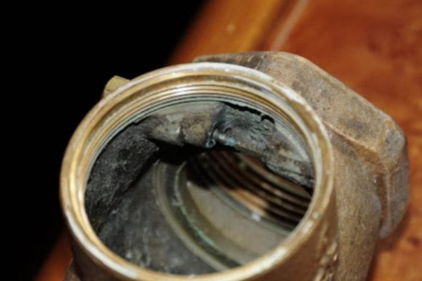
3. Preventing Corrosion and Scaling

Corrosion and scaling can lead to reduced performance and eventual valve failure. This is particularly common when the valve is used in harsh chemical environments or with hard water.

Solution: Choose corrosion-resistant materials like stainless steel or PVC when dealing with corrosive fluids. Regularly clean the valve and inspect it for early signs of corrosion or scale buildup.

4. Repair vs. Replacement: When to Make the Call

Deciding whether to repair or replace a valve depends on the extent of damage.

Repair: If the issue is minor, such as worn seats or seals, replacing these parts can extend the valve’s life.

Replacement: If the valve body is corroded or severely damaged, replacement is usually more cost-effective and safer in the long run.

Conclusion

By carefully evaluating your system’s requirements and considering the unique benefits and limitations of different ball valve designs, you can choose a valve that best fits your specific application, leading to improved efficiency and reduced downtime. For further assistance in selecting the ideal ball valve for your system or to address any specific questions, feel free to reach out to our team of experts.


FAQ

What is a ball valve used for?

Ball valves are used to control the flow of liquids and gases in various systems. They are commonly found in plumbing, industrial fluid systems, and hydraulic applications due to their simple operation and reliability.

How does a ball valve work?

A ball valve operates by rotating a spherical ball with a hole through it. When the hole aligns with the pipeline, fluid flows through. A 90-degree turn closes the valve, blocking the flow.

What materials are ball valves made from?

Ball valves are typically made from materials like brass, stainless steel, and PVC. The material selection depends on the application, fluid type, and environmental conditions.

What is the difference between a full-port and a reduced-port ball valve?

A full-port ball valve allows full flow with no restriction, matching the diameter of the pipe, while a reduced-port ball valve has a smaller opening, slightly restricting flow.

Can ball valves be used for throttling?

Although ball valves can be partially opened for throttling, they are primarily designed for on/off control. Prolonged throttling can lead to wear and tear.

How do I know when to replace a ball valve?

Replace a ball valve if it shows signs of leaking, corrosion, or stiff operation that can’t be resolved through maintenance. Severely damaged valves should be replaced rather than repaired.

Top Types of Check Valves and Their Applications Explained banner

Top Types of Check Valves and Their Applications Explained

The importance of check valves lies in their ability to maintain system integrity by preventing reverse flow, which can cause equipment failure, contamination, or process disruption. In industries where fluid dynamics are critical, such as oil and gas, chemical processing, and HVAC systems, check valves protect pumps, pipelines, and other equipment from damage caused by backflow. Additionally, they ensure that systems operate at optimal efficiency by regulating flow direction, contributing to overall operational safety and cost-effectiveness.

How Check Valves Work

Basic Operation Mechanism

Check valves are automatic valves designed to permit fluid flow in one direction and prevent reverse flow in a system. The basic working principle involves a mechanism that opens the valve when there is forward flow and closes it when the flow reverses. In normal operation, when fluid moves in the intended direction, pressure pushes the valve’s disc (or other closing mechanism) away from the seat, allowing the fluid to pass. If the flow reverses, the backpressure causes the disc to return to its seated position, sealing off the passage and preventing backflow.

This one-way operation is critical in ensuring the protection of sensitive equipment like pumps, compressors, and pipelines from damage due to reverse flow. It also helps maintain the efficiency and safety of the system by preventing contamination, fluid loss, and pressure surges.

Check Valve Selection

Components of a Check Valve

Check valves are simple devices with several key components that work together to regulate fluid flow:

Body: The outer casing of the valve, is typically made from materials such as stainless steel, brass, or plastic, depending on the application and fluid type.

Disc: The movable part that controls the flow. In different types of check valves, this may be a ball, diaphragm, or plate, depending on the design.

Seat: The part of the valve where the disc rests when closed. It ensures a tight seal to prevent backflow.

Hinge or Spring Mechanisms: Depending on the valve type, either a hinge (as in a swing check valve) or a spring (as in a spring-loaded check valve) helps control the movement of the disc. Springs are used to assist the closure of the valve, especially in vertical installations, while hinges work in gravity-based designs.

Inlet and Outlet Ports: The two ends of the valve through which fluid enters and exits, respectively. These ports are connected to the pipeline, ensuring the check valve fits into the system seamlessly.

Why Choosing the Right Type Matters

Selecting the appropriate type of check valve is crucial to ensure efficient and reliable operation. Different types of check valves are designed for specific applications, flow characteristics, and system conditions. Using the wrong check valve can lead to several problems:

Inefficiency: A check valve that doesn’t match the system’s pressure or flow requirements can create excessive pressure drops, reducing the overall efficiency of the system. For example, a valve that requires too much pressure to open might restrict fluid flow, leading to wasted energy.

Equipment Failure: If a check valve fails to close properly or operates too slowly, it can cause reverse flow, potentially damaging pumps, compressors, or other equipment. Water hammer, a high-pressure surge caused by sudden valve closure, can also occur if the wrong type of check valve is used.

Leakage: If the valve components such as the seat or disc are not designed to handle the system’s fluid properties, leaks can occur. This can result in contamination, loss of fluid, or even system failure, particularly in sensitive industries like chemical processing or food production.

Thus, choosing the right check valve for the specific fluid type, system pressure, and flow rate is essential to ensure system safety, efficiency, and long-term reliability.

Top Types of Check Valves

Swing Check Valve 

Design and Function

A swing check valve operates using a hinged disc (or flapper) that swings open to allow flow in the forward direction and closes when the flow reverses, preventing backflow. The valve’s design allows fluid to pass through with minimal resistance, and when the flow decreases or reverses, gravity or backpressure pushes the disc back into its seat, sealing the valve and stopping reverse flow. The swinging mechanism makes it ideal for horizontal installations.

Advantages

Low-pressure drop: The swing check valve allows fluid to pass with minimal resistance, reducing pressure loss in the system.

Ideal for low-velocity flows: The design is well-suited for systems where the flow rates are low and consistent, such as in water distribution systems.

Limitations

Not suitable for pulsating flows: The valve may wear out faster in systems with rapid flow changes, leading to improper sealing.

Potential for water hammer: In high-velocity systems, the valve’s rapid closure can cause water hammer, leading to pressure surges that can damage equipment.

Common Applications

Water and wastewater systems: The low-pressure design of swing check valves makes them ideal for water distribution and wastewater systems.

HVAC systems: They are commonly used in heating, ventilation, and air conditioning systems to regulate fluid flow and prevent backflow.

Oil and gas pipelines: In these industries, swing check valves help maintain the efficiency and safety of the pipeline systems by preventing backflow in low-velocity applications.

Ball Check Valve 

Design and Function

A ball check valve uses a spherical ball that moves within the valve body to block reverse flow. When fluid flows forward, the pressure lifts the ball off the seat, allowing the fluid to pass. When the flow reverses, the ball is forced back into the seat, creating a tight seal that prevents backflow. The simplicity of its design ensures that the valve works effectively in a range of fluid types, especially those containing particulates or debris.

Advantages

Simple design, low maintenance: The lack of complicated moving parts makes ball check valves easy to maintain and ideal for systems that need reliability.

Effective in systems with contaminated media: The ball’s ability to handle particulate matter makes this valve ideal for slurry or viscous fluids, where debris could hinder other types of valves.

Limitations

May cause higher pressure drops: Due to the design, ball check valves may result in slightly higher pressure drops compared to other types of check valves.

Not suitable for low-pressure systems: In low-pressure applications, the ball may not seat properly, leading to leakage or inefficient operation.

Common Applications

Pump discharge applications: Ball check valves are commonly used at the outlet of pumps to prevent reverse flow and maintain system integrity.

Slurry and viscous fluid systems: In industries such as mining or wastewater treatment, where fluids may contain particulates, ball check valves excel.

Food processing industries: Their ability to handle fluids with varying viscosity makes ball check valves a good choice for food and beverage applications.

check valve types

Lift Check Valve

Design and Function

In a lift check valve, the disc or piston moves vertically within the valve body to allow forward flow and closes when the flow reverses. As forward flow pressure increases, it lifts the disc off the seat, allowing fluid to move through. When the flow decreases or reverses, gravity or backpressure causes the disc to fall back into place, sealing the valve and stopping reverse flow. Lift check valves are well-suited for horizontal and vertical installations, provided there is sufficient pressure.

Advantages

Suitable for high-pressure applications: Lift check valves are robust enough to handle high-pressure systems, making them ideal for heavy-duty industrial processes.

Effective in horizontal and vertical piping: The design allows the valve to work in both horizontal and vertical orientations, providing flexibility in system design.

Limitations

Not ideal for dirty or slurry media: The tight clearance between the disc and the seat can become blocked or damaged by particulate matter, leading to valve failure.

Requires proper alignment for optimal functioning: Proper installation is critical to ensure that the disc lifts and seats correctly.

Common Applications

Steam and gas systems: Lift check valves are often used in steam and high-pressure gas systems due to their ability to withstand high temperatures and pressures.

High-pressure water applications: They are commonly used in high-pressure water pipelines where forward and reverse flow needs to be carefully controlled.

Chemical and petrochemical industries: The valve’s ability to withstand high pressures makes it suitable for use in chemical and petrochemical processing plants.

Diaphragm Check Valve

Design and Function

A diaphragm check valve uses a flexible rubber or elastomer diaphragm that flexes open under forward flow pressure and closes when the flow reverses. The diaphragm acts as both the disc and the seal, creating a smooth, tight closure that prevents backflow. These valves are commonly used in systems where maintaining sanitary conditions or avoiding contamination is critical.

Advantages

Suitable for sanitary applications: Diaphragm check valves are designed to meet hygiene standards, making them ideal for food, beverage, and pharmaceutical industries.

Prevents contamination, ideal for sensitive media: The diaphragm design ensures a tight seal, preventing contaminants from entering the system and protecting sensitive fluids.

Limitations

Limited use in high-pressure environments: Diaphragm check valves are not suitable for very high-pressure systems, as the diaphragm may fail under intense pressure.

Susceptible to wear from abrasive fluids: Abrasive media can damage the diaphragm, leading to leaks and reduced valve efficiency over time.

Common Applications

Pharmaceutical and food processing: Diaphragm check valves are widely used in these industries due to their ability to maintain sanitary conditions and avoid contamination.

Medical equipment: Their ability to handle sensitive media makes them suitable for use in medical devices that require precise fluid control.

Chemical dosing systems: Diaphragm check valves are commonly used in low-pressure chemical dosing systems where contamination must be avoided.

Wafer Check Valve

Design and Function

Wafer check valves are compact, thin valves that use a dual-plate or single-disc design to regulate flow. The discs swing open when fluid flows forward and close when the flow reverses, creating a compact and efficient sealing mechanism. The wafer-style design allows the valve to be installed between two flanges, making it ideal for systems where space is limited.

Advantages

Space-saving, compact design: The thin, lightweight design of wafer check valves allows for installation in tight spaces, reducing the overall size and weight of the system.

Low weight and easy to install: Wafer check valves are simple to install and require minimal support due to their lightweight construction.

Limitations

Not suited for high-viscosity fluids: The design may struggle to accommodate thicker, more viscous fluids, as the lightweight discs may not close effectively.

Limited to smaller pipelines: Wafer check valves are typically used in smaller-diameter pipes due to their compact size and design.

Common Applications

Power plants and energy systems: Wafer check valves are often used in power generation systems, where space is a premium, and compact designs are needed.

HVAC systems: These valves are ideal for HVAC systems, providing reliable flow control in tight spaces.

Industrial piping systems: Wafer check valves are used in a variety of industrial applications, particularly where space constraints and flow efficiency are key considerations.

Spring-Loaded Check Valve

Design and Function

A spring-loaded check valve uses a spring mechanism to assist the closure of the valve. In this design, the valve disc or piston is connected to a spring that automatically closes the valve when forward flow stops. The spring ensures a quick, reliable closure, preventing backflow and water hammer in systems with pulsating flows or high-pressure conditions.

Advantages

Prevents water hammer: The spring mechanism ensures a smooth, controlled closure that prevents the pressure surges that lead to water hammer.

Reliable operation even in vertical installations: Spring-loaded check valves are effective in both horizontal and vertical installations, providing flexibility in system design.

Limitations

Higher pressure drop due to the spring: The presence of the spring can cause a higher pressure drop, reducing system efficiency in certain applications.

Regular maintenance required in high-use systems: Over time, the spring may wear out or lose tension, requiring periodic maintenance to ensure reliable operation.

Common Applications

Water pumping systems: Spring-loaded check valves are commonly used in water pumping systems, where preventing backflow is critical.

Compressed air systems: These valves are also widely used in compressed air applications to maintain system pressure and prevent reverse flow.

Chemical processing plants: The quick closure and reliability of spring-loaded check valves make them ideal for use in chemical processing, where fluid control is crucial.

How to Select the Right Check Valve

Considerations Based on Application

Media Type (Liquids, Gases, Slurries)

The type of fluid flowing through the system plays a significant role in selecting the right check valve. Some check valves are designed to handle clean liquids, while others are better suited for gases or slurries containing particulates.

Liquids: For clean water or other liquid systems, swing or lift check valves are commonly used. However, for contaminated or viscous liquids, such as those in wastewater or food processing, a ball check valve may be more effective, as it can handle particles without jamming.

Gases: Systems carrying gases require valves with minimal leakage. Lift check valves or spring-loaded check valves are good choices for gas systems due to their ability to provide a reliable seal.

Slurries: In slurry systems, where the fluid contains suspended solids, the diaphragm or ball check valves are often preferred. These designs are less prone to clogging or wear from abrasive particles.

Pressure and Temperature Ranges

The operating pressure and temperature of the system should also guide valve selection. Different check valve types are designed to withstand varying pressure and temperature levels.

High-pressure systems: Lift and spring-loaded check valves are ideal for high-pressure applications because of their robust design and ability to handle extreme conditions.

Low-pressure systems: For low-pressure systems, a swing check valve may be sufficient, as it offers low resistance and minimal pressure drop.

Temperature considerations: In high-temperature environments, such as steam or chemical processing, material compatibility becomes critical. Metal-bodied valves, such as stainless steel or brass, are generally more suited to high temperatures, while plastic or rubber-based valves may degrade quickly.

Flow Rates and System Design

Flow rate is another important consideration when selecting a check valve. Valves must be chosen based on the desired flow capacity to avoid unnecessary pressure drops or system inefficiencies.

Low-velocity flows: Swing check valves are ideal for low-flow systems, as they open easily with minimal pressure. However, in systems with fluctuating or pulsating flow, this valve type may not seal effectively, leading to water hammer or system damage.

High-velocity flows: Spring-loaded check valves or lift check valves are better suited for systems with higher flow rates or pressure fluctuations. Their design ensures quick closure to prevent reverse flow, even at high velocities.

Piping configuration: System layout is also important. Wafer check valves, for instance, are compact and ideal for space-constrained systems. They can be installed between flanges in tight piping configurations.

Factors to Consider When Choosing a Check Valve

Pressure Drop

Pressure drop refers to the reduction in fluid pressure as it passes through the valve. Different valve designs cause varying degrees of pressure loss, which can impact the system’s efficiency.

Swing check valves: These valves generally cause a low-pressure drop due to their larger flow passage and smooth operation. They are ideal for systems where maintaining minimal resistance is critical.

Ball check valves: While effective in many applications, ball check valves may result in higher pressure drops compared to other types because of the smaller flow area created by the ball.

Spring-loaded check valves: These valves tend to introduce more pressure drop due to the spring mechanism resisting flow. However, they offer reliable performance in high-pressure systems.

It’s important to balance the need for preventing reverse flow with the impact the valve will have on overall system pressure.

Installation Orientation

The orientation of the valve within the system, whether horizontal or vertical, can influence valve performance.

Horizontal installation: Swing check valves and ball check valves are more effective in horizontal systems where gravity helps keep the valve disc or ball in position when closed.

Vertical installation: For vertical systems, particularly those with upward flow, lift check valves and spring-loaded check valves are better suited, as they use gravity or spring tension to ensure a secure seal even when fluid is not flowing. Installing a swing check valve in vertical piping can lead to operational issues if the disc doesn’t close properly.

Material Compatibility

The material of the check valve must be compatible with the media to avoid corrosion, wear, or contamination. Different materials offer varying levels of resistance to chemicals, temperature, and abrasion.

Metal valves: Stainless steel, brass, and cast iron valves are commonly used in systems involving high temperatures, chemicals, or pressure. Stainless steel, in particular, offers excellent corrosion resistance, making it suitable for aggressive chemicals or corrosive fluids.

Plastic valves: Plastic valves made from materials like PVC or polypropylene are suitable for lower-pressure, non-corrosive applications such as water systems. However, they are less durable under high temperatures or when exposed to harsh chemicals.

Elastomers and rubber: Diaphragm check valves often use elastomer components, such as EPDM or PTFE, to handle sensitive fluids without contamination. Care must be taken to ensure these materials are compatible with the chemicals being transported, as some chemicals can cause degradation.

Check Valves fail

Maintenance and Lifespan of Check Valves

Regular maintenance is essential for ensuring the long-term performance and safety of check valves. While check valves are designed for durability, they are not immune to wear and tear. Maintenance practices vary depending on the valve type and the environment in which it operates.

Inspection Frequency

Establishing a routine inspection schedule is important to catch early signs of wear, corrosion, or malfunction. Regular inspections help identify issues like valve sticking, leakage, or degradation before they lead to system failure.

Swing check valves: The hinge or disc may wear down over time, especially in high-use or abrasive applications. Regular inspection of these components is essential to prevent operational issues.

Spring-loaded check valves: Over time, the spring may lose tension or become corroded. Regular checks of the spring mechanism can help prevent valve malfunction, particularly in high-pressure systems.

Diaphragm check valves: Diaphragms should be inspected frequently in systems where they come into contact with abrasive or corrosive media. They can wear down or become brittle, leading to leakage or valve failure.

Cleaning and Debris Removal

In systems transporting slurries or fluids containing particulates, debris can accumulate in the valve, causing clogging or improper sealing. Ball check valves, in particular, are susceptible to clogging in systems with high levels of contamination. Regular cleaning or flushing of the system can extend the life of the valve and maintain performance.

Valve Replacement

Even with regular maintenance, check valves have a finite lifespan. Knowing when to replace a check valve is important to prevent leaks, system damage, or inefficient operation. Monitoring signs like increased pressure drops, leakage, or sluggish operation can help determine when a valve has reached the end of its useful life.

Conclusion

Selecting the correct check valve is essential for maintaining system efficiency and preventing costly issues such as reverse flow, water hammer, or equipment failure. It is important to match the valve type to the media, pressure, flow rate, and system design to ensure reliable performance and longevity. Additionally, regular maintenance and inspection are key to extending the life of the valve and keeping your system running smoothly.


FAQ

What is a check valve?

A check valve is a one-way valve that allows fluid to flow in one direction and prevents reverse flow.

How does a check valve work?

Check valves use a disc, ball, or diaphragm that opens when fluid flows forward and closes when the flow reverses, preventing backflow.

What are the main types of check valves?

Common types of check valves include swing check valves, ball check valves, lift check valves, diaphragm check valves, wafer check valves, and spring-loaded check valves.

Where are check valves used?

Check valves are widely used in industries such as oil and gas, water systems, HVAC, chemical processing, and pharmaceuticals.

Can a check valve be installed vertically?

Yes, certain types of check valves, like lift check valves and spring-loaded check valves, can be installed vertically, but proper orientation must be ensured for effective operation.

What causes a check valve to fail?

Common causes of check valve failure include debris buildup, wear and tear of internal components, improper installation, or using the wrong valve type for the system.

How Ball Valves Work banner

How Ball Valves Work: A Simple Guide to Their Functionality

Ball valves are essential components in fluid control systems, designed to regulate the flow of liquids and gases with remarkable efficiency. Their simplicity, reliability, and ability to completely shut off or allow flow make them popular choices across various industries, from plumbing and water management to oil, gas, and chemical processing. Unlike other types of valves, ball valves stand out for their quick operation and minimal wear, making them ideal for a wide range of applications where precision and durability are critical.

What Is a Ball Valve?  

Definition

A ball valve is a mechanical device used to control the flow of fluids—liquids or gases—by using a rotating spherical ball inside the valve body. The ball has a hole, or port, through its center, which allows fluid to pass when aligned with the valve openings. When rotated 90 degrees, the ball blocks the flow, effectively shutting off the passage. Ball valves are widely known for their reliability, quick operation, and ability to provide a complete shut-off, making them a popular choice for various industries, including water, gas, and chemical systems.

Ball valves can handle high pressures and temperatures, making them versatile for different applications. Their simple operation, along with the ability to withstand wear, makes them a go-to valve type for situations where frequent opening and closing are required.

Ball Valve component

Key Components

Body

The body of a ball valve is the outer shell that houses all internal components. It is typically made from materials such as brass, stainless steel, or PVC, depending on the application. The material choice determines the valve’s durability, corrosion resistance, and ability to handle different types of fluids and environmental conditions. For industrial applications, metals like stainless steel are preferred due to their strength and resistance to harsh chemicals or high temperatures.

Ball

At the heart of the ball valve is a spherical ball, which is designed with a hollow center or port. When the hole in the ball aligns with the valve’s inlet and outlet, the fluid can flow through without restriction. Rotating the ball 90 degrees turns the solid side of the ball toward the flow, stopping it entirely. The precision with which the ball rotates ensures that ball valves offer an excellent seal, making them highly effective for on/off flow control.

Seats

The seats in a ball valve are soft or metal rings that fit tightly around the ball, providing a seal between the ball and the valve body. These seats prevent fluid from leaking when the valve is closed. Depending on the valve design, materials for the seats can vary, with common choices being Teflon, rubber, or metal. The seats play a critical role in ensuring the valve’s tight closure and long-term functionality by reducing wear on the ball and maintaining sealing integrity.

Stem

The stem connects the ball to the actuator or handle. When the actuator or handle is turned, the stem rotates, which in turn moves the ball. Stems are designed to withstand the torque exerted during operation and are typically made from the same material as the valve body to ensure durability. A properly functioning stem is crucial for smooth valve operation, as it allows the ball to rotate efficiently with minimal effort.

Actuator or Handle

Ball valves are operated manually using a handle or automatically using an actuator. Manual valves typically have a lever handle, which provides an easy, visual indication of whether the valve is open (aligned with the flow) or closed (perpendicular to the flow). For automated systems, electric or pneumatic actuators are used to control the valve remotely. This is especially useful in applications where manual control is impractical or unsafe.

Function Overview

In general, ball valves function by offering two main states: fully open or fully closed. In the open position, the ball’s port allows fluid to pass through freely, with minimal restriction. When closed, the solid part of the ball blocks the flow, creating a tight seal. Ball valves are primarily used for shut-off applications, where their reliable and quick operation is essential. Because they do not throttle flow, ball valves are less suitable for fine-tuning fluid control, but they are ideal for applications that require complete on/off control.

How Ball Valves Work

Basic Mechanism

At the core of a ball valve’s functionality is a rotating spherical ball with a hollowed-out center (or “bore”). The most common mechanism involves turning the ball 90 degrees to open or close the valve. When the ball is rotated so that its bore aligns with the flow path of the fluid, the valve is in the “open” position, allowing the fluid to pass through. Conversely, when the ball is turned so that the solid part of the ball faces the flow path, the valve is in the “closed” position, blocking the fluid from flowing.

This 90-degree rotational movement is the fundamental operation of a ball valve, and it can be easily controlled using a handle or an actuator. In manual systems, the handle is turned 90 degrees to open or close the valve, providing a quick and clear visual indicator of the valve’s status. When the handle is parallel to the pipe, the valve is open; when it’s perpendicular, the valve is closed.

Bore Alignment and Flow

The ball inside the valve has a bore or opening that runs through it. When this bore is aligned with the valve’s inlet and outlet ports, the fluid flows freely. In this position, the cross-sectional area available for the fluid to pass through is almost identical to that of the connected pipe, ensuring minimal flow restriction.

However, when the ball is rotated 90 degrees, the bore is no longer aligned with the ports, and the solid part of the ball blocks the flow entirely. The quick transition from open to closed is one of the main reasons ball valves are used in applications where complete shut-off is needed.

Flow Control Mechanism

Ball valves are mainly used for simple on/off control of fluid flow. Unlike other types of valves, such as globe valves or needle valves, ball valves are not designed to throttle or regulate flow. This is because the flow control mechanism of a ball valve does not allow for precise adjustments in fluid flow. Instead, it excels in providing a reliable, leak-proof seal when closed and an unobstructed flow when open.

The binary nature of flow control (either fully open or fully closed) makes ball valves ideal for situations that demand rapid and complete shut-off. In scenarios where throttling or fine flow control is required, ball valves are generally not recommended because partial opening can lead to damage or wear on the seats and ball, resulting in leaks over time.

Ball Valves uses

Full Port vs. Reduced Port

There are two primary configurations of ball valves: full port and reduced port.

Full Port Ball Valves:

In a full port ball valve, the bore inside the ball has the same diameter as the connected pipe. This ensures that there is no restriction in flow, and the fluid passes through as if the valve wasn’t there at all. Full port ball valves are used in applications where maintaining the maximum flow rate is critical, such as in high-demand industrial processes.

Reduced Port Ball Valves:

In reduced port (or standard port) ball valves, the bore is smaller than the diameter of the connected pipe. This creates a slight restriction in the flow, leading to some pressure drop as the fluid moves through the valve. Reduced port ball valves are used in situations where the highest flow rate is not essential, but the need for reliable shut-off remains.

The choice between full port and reduced port valves depends on the specific application. Full port valves are ideal for systems requiring high flow rates and minimal pressure loss, while reduced port valves are more suitable for systems where cost savings and compact size are more important considerations than maintaining the full flow rate.

Directional Flow

Ball valves are versatile in terms of the directional flow they can accommodate, making them suitable for a wide range of fluid control applications.

Single-Direction Flow

In many systems, ball valves are used for single-direction flow, meaning that the fluid is intended to move in one direction through the valve. These valves are designed to allow fluid to pass when the valve is open and block the fluid entirely when the valve is closed. Single-direction ball valves are commonly used in applications such as plumbing systems or industrial fluid control, where controlling flow in one direction is essential.

Multi-Directional Flow

Ball valves can also be designed to handle multi-directional flow, providing even greater versatility. Multi-port ball valves typically feature two or more ports, allowing them to direct fluid flow in different directions or switch between different flow paths. These valves are ideal for applications that require fluid diversion, mixing, or distribution.

For example:

Two-Way Ball Valves: These are the most common type, allowing fluid to flow in or out of two ports. A two-way valve has a simple on/off function that controls fluid flow in one path.

Three-Way Ball Valves: These valves have an additional port, which enables them to direct flow from one inlet to either of two outlets or vice versa. They are commonly used in systems that need to divert or mix fluid flow. The ball inside the valve can be designed in an L or T shape, providing different flow configurations based on the needs of the system.

Accommodating Different Flow Types

The design of ball valves allows them to handle a variety of flow types, whether it’s a simple one-way flow or a more complex multi-directional flow setup. The ball’s ability to rotate easily and block or permit flow in specific directions makes it possible to use ball valves in highly specialized applications where precise control of fluid movement is required.

For instance, in systems requiring alternate flow paths or fluid distribution, a multi-port ball valve can efficiently switch between different outlets, reducing the need for multiple valves and simplifying the piping layout.

Types of Ball Valves  

Based on Bore Size

The size of the bore, or the opening inside the ball, directly affects how fluid flows through the valve. There are three common types of ball valves based on bore size:

Full Port Ball Valves

Description:

Full port (or full bore) ball valves have a bore that matches the diameter of the connected pipe. This design ensures that there is no restriction to fluid flow, allowing the maximum flow rate through the valve without any pressure drop. The ball inside the valve has a larger opening, providing an uninterrupted flow of fluid.

Advantages:

Maximum flow with minimal friction loss.

No significant pressure drop.

Ideal for applications where maintaining the flow rate is critical, such as in pipelines or systems that require high-volume flow.

When They Are Used:

Full port ball valves are commonly used in industries where maintaining high flow efficiency is essential, such as in gas pipelines, water distribution systems, and processing plants. They are also favored in systems where fluid characteristics (such as particle size) demand that the flow path remains unobstructed.

Reduced Port Ball Valves

Key Features:

In reduced port ball valves (also known as standard port ball valves), the bore is smaller than the pipe diameter, leading to a reduction in flow capacity. This design results in a slight pressure drop because the fluid flow is constricted as it passes through the valve.

Applications:

Suitable for applications where a slight reduction in flow is acceptable.

Cost-effective due to smaller ball size and body dimensions, which reduce material usage.

Commonly used in water distribution systems, chemical processes, and HVAC systems where full flow is not always required.

V-Port Ball Valves

How They Offer Better Flow Control:

V-port ball valves are designed with a “V” shaped notch in the ball, allowing for more precise flow control. This feature makes them suitable for throttling applications, where controlling the rate of fluid flow is critical. As the valve opens, the V-notch creates a more controlled, gradual increase in flow compared to standard ball valves.

Precise Regulation:

Allows for accurate flow regulation by controlling the fluid at different stages of valve opening.

More resistant to wear in throttling applications due to the gradual opening and closing process.

When They Are Used:

V-port ball valves are ideal for applications requiring precise flow control, such as chemical processing, water treatment, and systems where fluids need to be delivered at a specific rate or pressure.

Based on Valve Design

Ball valves can also be categorized based on their internal design, particularly in how the ball is supported within the valve body.

Floating Ball Valve

How It Works:

In floating ball valves, the ball is suspended inside the valve body by the seats, without any additional support mechanisms. The ball is free to move slightly in response to fluid pressure, which helps to create a tight seal when the valve is in the closed position.

Features:

Simple design and lower cost.

The floating ball pushes against the downstream seat to create a reliable seal.

Best suited for lower to medium pressure applications.

Applications:

Floating ball valves are commonly used in industries such as water distribution, oil and gas, and manufacturing systems. They are especially effective in low- to medium-pressure environments where a tight shutoff is needed.

Trunnion Ball Valve

Working Principle:

Trunnion ball valves feature an additional mechanical anchoring system for the ball. The ball is supported by a trunnion, which is a shaft that holds the ball in place and reduces the stress on the seats. This design allows the valve to operate under higher pressures without excessive wear on the seats.

Suitability for Higher Pressure Systems:

Handles higher pressures more effectively than floating ball valves.

Less torque required to operate the valve, which makes it easier to automate.

Ideal for high-pressure applications in oil and gas, power generation, and petrochemical industries.

Applications:

Trunnion ball valves are typically found in large-scale systems where high pressure and flow control are essential, such as in gas transmission pipelines, power plants, and large-scale water systems.

2-way high pressure ball valves manufacturer

Based on Material

The material of the valve body is another key factor in determining its suitability for different applications. The most common materials used for ball valves are brass, stainless steel, and PVC.

Brass Ball Valves

Durability and Resistance:

Brass is a durable material that offers good resistance to corrosion and wear, making it suitable for various fluid types, including water, gas, and certain chemicals. Brass ball valves are widely used in plumbing and low- to medium-pressure applications due to their cost-effectiveness and durability.

Applications:

Residential and commercial plumbing.

HVAC systems.

Low-pressure industrial processes.

Stainless Steel Ball Valves

Strength and Corrosion Resistance:

Stainless steel ball valves are highly resistant to corrosion, high temperatures, and pressure. They are ideal for use in harsh environments and systems that require the handling of aggressive chemicals, such as in the food and beverage industry, marine applications, and oil and gas systems.

Applications:

Chemical processing.

Oil and gas production.

Marine systems and seawater applications.

PVC Ball Valves

Lightweight and Cost-Effective:

PVC (polyvinyl chloride) ball valves are lightweight, inexpensive, and resistant to corrosion. They are commonly used in systems that handle non-corrosive fluids, such as water or certain chemicals. However, they are not suited for high-pressure or high-temperature applications.

Applications:

Irrigation systems.

Swimming pool equipment.

Water distribution in residential and commercial settings.

Based on Operation Mechanism

Ball valves can be manually operated, or they can be automated using electric or pneumatic actuators. Each method of operation has its own advantages depending on the system’s needs.

Manual Ball Valves

Handle-Operated Ball Valves:

Manual ball valves are the simplest type, operated by turning a lever or handle to rotate the ball inside the valve. This type of valve is commonly used in systems where ease of operation and immediate feedback on the valve’s status (open or closed) are essential.

Applications:

Plumbing systems.

HVAC systems.

Low-pressure industrial applications.

Electric Ball Valves

Automation and Electric Actuation:

Electric ball valves are automated using electric actuators that turn the valve on and off remotely. These valves are often used in systems that require precise control over the valve’s operation or where manual operation is impractical due to the location of the valve.

Applications:

Automated manufacturing processes.

Remote pipeline control.

Building automation systems.

Pneumatic Ball Valves

Compressed Air for Valve Operation:

Pneumatic ball valves are operated using compressed air to move the actuator, allowing for rapid opening and closing. Pneumatic valves are typically used in industrial systems where speed and reliability are critical. They are especially useful in hazardous environments where electric components could pose a risk.

Applications:

Oil and gas systems.

Chemical plants.

Industrial automation.

Limitations and Considerations

While ball valves are highly versatile and reliable for on/off flow control, they do have some limitations that should be considered when selecting them for specific applications.

Not Suitable for Throttling

Ball valves are primarily designed for quick, complete shut-off or opening, but they are not ideal for flow regulation or throttling. The key reason lies in the design of the valve. Unlike globe or needle valves, which are specifically engineered to allow gradual adjustment of flow, ball valves operate in a binary manner — they are either fully open or fully closed.

Why They Aren’t Used for Flow Regulation:

Precision: Ball valves cannot provide the fine control needed for throttling. Partial opening of the ball creates an uneven flow path, which can cause turbulence and irregular flow rates.

Wear and Tear: Attempting to use a ball valve for throttling can cause the ball and the seats to wear prematurely. The high velocity and pressure of fluids passing through a partially open valve can erode the components, leading to leaks or valve failure over time.

Cavitation: In some cases, throttling with a ball valve can cause cavitation, where rapid pressure changes create vapor bubbles that can damage the valve’s internal parts. This can reduce the valve’s lifespan and effectiveness.

For applications requiring precise control over fluid flow, it’s advisable to use valves specifically designed for throttling, such as globe or needle valves.

Potential for Wear and Tear

Ball valves are known for their durability, but they are not immune to wear and tear, especially in demanding environments. Over time, certain components of the valve, particularly the seals and seats, can degrade due to continuous use, leading to reduced performance and potential failure.

Common Issues:

Wear on Seals and Seats: The seats and seals inside the valve are critical for creating a tight, leak-free seal when the valve is closed. However, with repeated operation, these components can wear out, especially if the valve is exposed to abrasive or corrosive fluids. This can lead to leaks or difficulty in fully closing the valve.

Erosion: In systems where high-pressure fluids flow through the valve at high speeds, the ball and seats can experience erosion. Over time, this erosion weakens the valve’s sealing ability, leading to leaks or failure to operate effectively.

Sticking or Seizing: In environments where the valve is exposed to harsh conditions, such as extreme temperatures or corrosive chemicals, the ball may stick or seize within the valve body. This makes it difficult or impossible to turn the valve without excessive force, potentially damaging the stem or handle.

To minimize wear and tear, regular maintenance and inspections should be carried out, and worn components such as seals and seats should be replaced as needed.

Pressure Limitations

While ball valves are highly effective in many low- to medium-pressure applications, they may not always be the best choice for extremely high-pressure systems. The design of ball valves — particularly floating ball valves — can create challenges in maintaining a reliable seal in high-pressure environments.

When to Consider Alternative Valve Types:

Floating Ball Valves: In high-pressure systems, floating ball valves may struggle to maintain a tight seal due to the increased pressure pushing the ball against the seats. This can result in leaks or difficulty operating the valve.

Trunnion Ball Valves: While trunnion ball valves are designed to handle higher pressures more effectively, even they have limits, particularly in systems where pressures exceed their rated capacity.

In systems with very high pressure, alternative valve types like gate valves or globe valves may provide more reliable performance. These valves are designed to withstand higher pressures without sacrificing sealing ability or durability.

Conclusion

Selecting the right type of ball valve is crucial for ensuring optimal performance in any system. Whether you need a full port valve for maximum flow, a trunnion valve for handling high pressure, or a brass or stainless steel valve for corrosion resistance, understanding the specific requirements of your application will guide you to the best choice. If you have any questions or need assistance in choosing the correct ball valve for your system, don’t hesitate to reach out.


FAQ

What is a ball valve used for?

A ball valve is used to control the flow of liquids or gases by opening, closing, or partially obstructing a flow path.

How does a ball valve work?

A ball valve works by rotating a ball with a hollow center inside the valve body. Turning the handle or actuator 90 degrees opens or closes the valve.

Can ball valves be used for throttling?

No, ball valves are not ideal for throttling as they are designed for full on/off control, not for precise flow regulation.

What materials are ball valves made of?

Ball valves can be made from materials like brass, stainless steel, and PVC, each suited for different types of fluids and environments.

What is the difference between a full port and a reduced port ball valve?

A full port ball valve has a bore equal to the pipe diameter, allowing maximum flow, while a reduced port valve has a smaller bore, causing some flow restriction.

Are ball valves suitable for high-pressure applications?

Some ball valves, like trunnion-mounted ball valves, are designed for high-pressure applications, while floating ball valves may not perform as well under extreme pressure.

Check Valves Types banner

Check Valves Types: Uses, and Key Selection Tips

Check valves are essentially mechanical devices designed to allow the flow of fluid or gas in one direction while preventing reverse flow. These valves operate automatically without the need for external control, relying on the pressure of the fluid or gas to open or close. Found in a wide range of applications, check valves are critical components in systems where backflow could cause damage, contamination, or inefficiency. Their primary role is to ensure that the media in a system flows smoothly in one direction, preventing any backward movement that could disrupt processes or damage equipment.

How Check Valves Work

Definition and Purpose

A check valve is a mechanical device that allows fluid or gas to flow in one direction while automatically preventing flow in the opposite direction. The main function of a check valve is to stop backflow, which can cause contamination, equipment damage, or process inefficiency. This ability to restrict reverse flow is crucial for maintaining the integrity and performance of fluid or gas systems in various industries. Check valves are used across many sectors to protect vital components like pumps, compressors, and pipelines from damage caused by backflow or pressure changes.

The role of check valves is especially important in systems where backflow can result in significant damage. For example, in pump systems, reverse flow can cause the pump to spin backward, leading to seal damage or overheating. In water treatment facilities, backflow can result in contamination of clean water with dirty or hazardous liquids. Therefore, the installation of check valves is vital for system reliability, safety, and protection against costly repairs or downtime.

Basic Mechanism

Check valves operate automatically without the need for manual control or external power. Their operation is dependent on the pressure differential between the forward (upstream) and reverse (downstream) flows. The valve opens when the forward pressure exceeds the reverse pressure, allowing fluid or gas to pass through. As long as the forward pressure is greater, the valve remains open, ensuring that the flow moves in the desired direction.

When reverse pressure increases and surpasses the forward pressure, the check valve closes. This closure happens due to gravity, spring force, or a pressure differential acting on the valve’s internal components, such as a disc, ball, or diaphragm. Once the valve is closed, it forms a tight seal, preventing any reverse flow. This simple yet effective mechanism ensures that the system is protected from backflow-related issues, without requiring constant monitoring or manual intervention.

Check Valves Design

Applications Overview

Check valves are employed in a wide variety of industries, making them a critical component in numerous applications. In the oil and gas industry, check valves are used to prevent backflow in pipelines that transport crude oil, gas, and other petrochemicals, protecting against dangerous leaks or contamination. Chemical processing plants rely on check valves to maintain unidirectional flow and prevent the mixing of chemicals that could lead to hazardous reactions or equipment corrosion.

In water systems, check valves prevent the backflow of potentially contaminated water, ensuring the safety and purity of drinking water supplies. They are often installed in wastewater treatment systems to avoid mixing clean water with sewage or industrial waste. Similarly, in HVAC systems, check valves prevent backflow in heating, ventilation, and air conditioning units, protecting compressors and other essential components from damage due to reverse flow.

Additionally, check valves are widely used in marine applications, food and beverage industries, and pharmaceutical production, where controlling the flow of fluids is critical for maintaining safety, quality, and regulatory compliance. In all these applications, check valves ensure smooth operation, equipment longevity, and system efficiency by preventing reverse flow and protecting the integrity of the process.

Types of Check Valves  

Ball Check Valves

Ball check valves are among the simplest and most commonly used types of check valves. They use a spherical ball to block the flow of fluid or gas in one direction and allow it to flow in the other. The ball sits on a seat, and when forward pressure is applied, the ball lifts to allow fluid to pass. When the pressure drops or reverses, the ball returns to the seat, sealing the valve and preventing backflow.

Uses: Ball check valves are typically found in low-pressure systems such as water pumps and wastewater applications. They are particularly effective in systems that handle clean liquids and gases with moderate flow rates.

Pros:

Simple design with few moving parts.

Durable and reliable for low-pressure applications.

Minimal maintenance is required.

Cons:

Prone to wear over time, especially in systems with particulate matter or high flow rates.

Not ideal for high-pressure or high-temperature environments.

Swing Check Valves

Swing check valves feature a disc that swings on a hinge or pivot to allow fluid to flow in one direction and close when the flow reverses. The swinging motion of the disc provides a full, unobstructed opening for fluid flow, making this type of valve suitable for systems with higher flow rates.

Uses: Swing check valves are widely used in moderate to high-flow systems such as HVAC (Heating, Ventilation, and Air Conditioning), water treatment plants, and large-scale fluid systems.

Pros:

Suitable for handling large volumes of fluid or gas.

Low pressure drop due to the full opening of the disc.

Cons:

The hinge mechanism can wear over time, requiring regular maintenance.

The valve may not close quickly in low-flow systems, potentially allowing some backflow.

Vulnerable to water hammer in high-pressure applications.

check valve types

Lift Check Valves

Lift check valves operate using a piston or disc that lifts vertically when forward pressure is applied, allowing flow. The valve closes when reverse pressure occurs, as the disc or piston is pushed back into its seat by gravity or system pressure.

Uses: Lift check valves are ideal for high-pressure applications, such as steam systems and compressed air pipelines. Their robust design makes them well-suited for handling aggressive conditions like high pressure and temperature.

Pros:

Excellent for high-pressure systems.

Can handle high temperatures, making them suitable for steam and industrial processes.

Cons:

Not ideal for viscous fluids as the piston may have difficulty lifting.

More complex design compared to other types, leading to higher maintenance needs.

Diaphragm Check Valves

Diaphragm check valves use a flexible diaphragm that opens and closes to control the flow of fluid. The diaphragm flexes under forward pressure, allowing the flow to pass, and seals the valve when the pressure drops or reverses. These valves are highly suited for handling sensitive or corrosive fluids.

Uses: Diaphragm check valves are frequently used in systems that handle corrosive or chemical fluids, especially in low-pressure environments. They are popular in industries like pharmaceuticals, food processing, and chemical production.

Pros:

Excellent for handling corrosive fluids and chemicals.

The flexible diaphragm prevents leaks and ensures a tight seal, even with sensitive fluids.

Cons:

Less suitable for high-pressure systems due to potential diaphragm damage.

Diaphragms may require replacement after extended use, especially in harsh chemical environments.

Wafer Check Valves

Wafer check valves are compact and designed to fit between two flanges in a pipeline. They are typically much thinner and lighter than other valve types, making them ideal for space-constrained applications. Wafer check valves often use a disc or plate that moves forward and backward to control the flow of fluid.

Uses: These valves are commonly used in pipelines where space is limited, such as industrial systems, water distribution, and marine applications. They are also favored for their ease of installation and cost-effectiveness.

Pros:

Lightweight and compact, making them ideal for tight spaces.

Easier and faster to install compared to other check valves.

Cost-effective for applications with limited space or budget.

Cons:

Not suitable for all pressure ranges, particularly in high-pressure systems.

Limited durability in applications that experience frequent pressure fluctuations.

Piston Check Valves

Piston check valves use a cylindrical piston that moves vertically inside the valve body to control fluid flow. As forward pressure increases, the piston lifts, allowing flow. When reverse pressure occurs, the piston moves downward to close the valve. This design provides excellent sealing for high-pressure systems.

Uses: Piston check valves are commonly used in high-pressure applications, including steam and industrial fluid systems. Their robust construction makes them highly suitable for handling extreme conditions.

Pros:

Reliable in high-pressure environments.

Provides a tight seal, preventing any backflow in critical systems.

Cons:

Regular inspection and maintenance are required to ensure optimal performance.

The piston mechanism can wear out over time, especially in harsh conditions.

Silent or Spring-Loaded Check Valves

Silent, or spring-loaded, check valves incorporate a spring mechanism that ensures quick closure when reverse flow is detected. The spring forces the valve shut almost immediately when the forward pressure drops, preventing backflow. These valves are particularly effective in systems where minimizing noise and preventing water hammer (the shockwave caused by sudden valve closure) is critical.

Uses: Silent check valves are used in systems requiring quick backflow prevention, such as HVAC systems, fuel lines, and applications where water hammer prevention is essential.

Pros:

Fast-acting closure prevents water hammer and other pressure-related issues.

Quiet operation, making them ideal for environments sensitive to noise.

Cons:

Higher initial cost compared to standard check valves due to the inclusion of the spring mechanism.

The spring may weaken over time, requiring replacement for continued effectiveness.

Key Uses for Check Valves in Different Industries

Water and Wastewater Systems

In water and wastewater systems, check valves play a critical role in maintaining clean and efficient operations. The primary function of check valves in these systems is to ensure unidirectional flow, preventing contamination from backflow. In potable water systems, it is crucial to avoid any reversal of flow that could introduce contaminants into the clean water supply. Check valves are installed at key points in the system to protect against potential backflow events caused by pressure fluctuations or pump failure.

In wastewater systems, check valves help maintain proper flow control, ensuring that sewage or industrial waste does not flow backward into the treatment plant or contaminate clean water supplies. Check valves in these applications are often used in combination with pumps to prevent damage from reverse flow when the pumps are not running. They ensure the consistent movement of water and wastewater, keeping treatment processes efficient and preventing environmental harm.

Oil and Gas Pipelines

In the oil and gas industry, pipelines carry valuable and often hazardous materials over long distances. Ensuring the safe and efficient transport of these materials is a top priority, and check valves play a vital role in preventing backflow, which could cause leaks, contamination, or even explosions. Check valves are commonly installed in both upstream and downstream operations to protect pumps and compressors from the risk of reverse flow, which could damage equipment or disrupt the entire system.

In oil and gas pipelines, check valves also prevent the mixing of different media within the system. For instance, in gas separation processes, the valves ensure that only the desired gas flows forward while preventing the backward movement of liquids or other gases that could compromise the integrity of the process. The reliability and durability of check valves in high-pressure environments make them indispensable in this industry.

Chemical Processing

The chemical processing industry requires precise flow control and protection from backflow to maintain safety and product quality. Check valves are essential in these systems, especially in handling corrosive chemicals that could damage equipment or cause dangerous reactions if not properly contained. The correct selection of check valves is crucial in this context, as the materials used for the valve must be compatible with the chemicals in the system to avoid corrosion or degradation over time.

In chemical plants, check valves prevent the backward flow of chemicals into sensitive equipment such as pumps, reactors, and mixers. This ensures that chemical processes remain stable and efficient, while also protecting workers and the environment from potential exposure to hazardous substances. Diaphragm check valves are often used in these applications due to their ability to handle corrosive fluids while maintaining a tight seal to prevent leaks.

Check Valve Applications

HVAC Systems

In heating, ventilation, and air conditioning (HVAC) systems, maintaining proper airflow and fluid circulation is essential for efficient operation. Check valves are commonly used in these systems to prevent the reverse flow of air or refrigerants, ensuring that HVAC units operate as designed without energy loss or mechanical damage. Swing check valves are often installed in ductwork or piping systems to maintain unidirectional flow, allowing air or fluids to circulate freely in the correct direction while closing off when flow reverses.

Silent or spring-loaded check valves are also popular in HVAC systems due to their ability to close quickly and quietly, preventing the occurrence of water hammer or other pressure surges that could damage equipment. These valves are essential in preventing refrigerant from flowing backward in cooling systems, ensuring the compressor remains protected. The fast closure of silent check valves reduces system noise, making them a preferred choice in noise-sensitive environments such as offices or residential buildings.

Key Selection Tips for Check Valves

Pressure and Flow Considerations

When selecting a check valve, one of the most critical factors to consider is the system’s pressure and flow rate. Each type of check valve operates differently under varying pressure conditions, and choosing the right one ensures efficient and reliable performance.

Pressure: Check valves must withstand the system’s operating pressure without failure. For high-pressure systems, such as steam applications or hydraulic lines, robust valves like pistons or lift check valves are more suitable due to their ability to handle high pressure. In contrast, low-pressure systems, such as water pumps or HVAC systems, can utilize ball or swing check valves, which are typically more cost-effective and designed for moderate pressure conditions.

Flow Rate: The flow rate of the system determines how easily the fluid or gas will pass through the check valve. Valves like swing check valves are ideal for systems with higher flow rates since they allow full, unobstructed flow. On the other hand, ball and piston check valves can handle moderate to lower flow rates but may restrict flow more than other types. Ensure that the valve selected does not cause a significant pressure drop in the system by impeding flow.

To properly size the valve, evaluate the system’s flow rate and pressure requirements in conjunction with the valve’s specifications. If the flow rate is too high for a given valve, it could result in damage or inefficient operation, while choosing a valve with a lower capacity could lead to restricted flow or premature failure.

Material Compatibility

The material of the check valve is another crucial consideration, especially when dealing with corrosive or abrasive environments. The valve’s material must be compatible with the fluid or gas it will control to avoid corrosion, wear, or degradation over time.

Stainless Steel: Stainless steel valves are highly resistant to corrosion, making them ideal for handling aggressive fluids, such as chemicals, seawater, or acidic solutions. Stainless steel check valves are commonly used in chemical processing plants, marine applications, and food processing industries where sanitary conditions and corrosion resistance are vital.

Brass: Brass check valves are widely used in plumbing and water systems due to their affordability, good corrosion resistance, and durability. They are effective in moderate-temperature environments but may not perform well with highly corrosive fluids.

Plastic (PVC or Polypropylene): For lower-pressure systems and applications handling mildly corrosive fluids, plastic check valves can be a cost-effective solution. They are often used in wastewater treatment, aquariums, and certain chemical processing applications. However, plastic valves are not suitable for high-temperature or high-pressure environments due to their lower heat and pressure tolerance.

Other Materials: In some cases, other specialized materials like bronze, carbon steel, or alloy materials may be required based on specific industry needs. For example, bronze valves are often used in marine applications for their superior resistance to seawater corrosion.

Selecting the correct material ensures the longevity of the valve and prevents potential leaks or failures due to corrosion or chemical incompatibility. Always check the chemical compatibility of the material with the system fluid.

Valve Type Selection

Selecting the right valve type depends on the characteristics of the system, including flow rate, pressure, and the desired function of the valve. Each type of check valve offers unique benefits, and choosing the wrong one can lead to inefficiency or system failure.

Ball Check Valves: Ball check valves are simple, reliable, and best for low-pressure systems with clean fluids. However, they may not be suitable for systems with high flow rates or viscous fluids, as the ball mechanism can create resistance.

Swing Check Valves: Swing check valves are ideal for high-flow systems, such as HVAC or water treatment plants. Their disc swings open fully, allowing unrestricted flow. However, they may require more frequent maintenance due to the wear on the hinge or pivot.

Lift Check Valves: Lift check valves, with their piston or disc mechanism, are designed for high-pressure environments, such as steam or compressed air systems. They are excellent for handling high-pressure fluids but are less effective for viscous or particulate-laden fluids.

Diaphragm Check Valves: For handling corrosive or sensitive fluids, diaphragm check valves are an excellent choice. Their flexible diaphragm design prevents leaks and can handle abrasive or chemically aggressive fluids, making them ideal for chemical processing.

Wafer Check Valves: Wafer check valves are compact and suitable for space-constrained applications like pipelines, but they are not always suitable for very high-pressure systems.

Silent or Spring-Loaded Check Valves: These valves are best suited for systems requiring quick backflow prevention, such as HVAC or fuel lines. They close rapidly and quietly, preventing water hammers but come at a higher cost.

Installation Space

Space constraints can significantly influence the choice of check valves. In many industrial systems, particularly pipelines or marine environments, there may be limited space for valve installation. Compact valve types, such as wafer check valves or piston check valves, are ideal in such scenarios. Wafer check valves are thin and designed to fit between two flanges, minimizing the need for extra space while still offering reliable performance.

If space is not a constraint, more traditional valve designs like swing or ball check valves can be used. However, always consider how the valve’s size and shape will affect the installation and the system’s layout. Failure to account for space limitations can lead to installation difficulties or necessitate system redesigns.

Maintenance Requirements

Maintenance is an important factor to consider when selecting a check valve. Depending on the system and environment, some valve types may require more frequent maintenance, while others can offer longer service intervals.

Swing Check Valves: These valves often require more maintenance due to the wear and tear on the hinge or pivot. Regular inspection is needed to ensure the disc swings freely and seals properly.

Ball Check Valves: These are low-maintenance valves due to their simple design with few moving parts. However, over time, the ball or seat may experience wear, especially in systems with particulate matter.

Diaphragm Check Valves: The diaphragm may require replacement in chemical applications where exposure to harsh fluids can degrade the material. However, they offer excellent sealing and reduced maintenance in many low-pressure systems.

Silent Check Valves: Spring-loaded check valves are low-maintenance but may require occasional inspection to ensure the spring mechanism functions correctly. They are known for long service life with minimal intervention.

Selecting a valve that aligns with your system’s maintenance capabilities can reduce downtime and operating costs. If regular maintenance is challenging, selecting a low-maintenance valve type may be more advantageous.

Special Considerations for Vertical or Horizontal Installations

The orientation of the valve during installation is another critical factor. Some check valves are designed to function best in horizontal installations, while others are suitable for both vertical and horizontal orientations.

Horizontal Installations: Valves like swing check valves typically perform well in horizontal pipelines, as the disc can swing freely with gravity.

Vertical Installations: Lift check valves, ball check valves, and spring-loaded check valves are often more effective in vertical installations, where gravity or spring force assists with valve closure. In these installations, it is crucial to ensure that the flow direction corresponds with the valve’s design.

Conclusion

Understanding the specific function of each check valve type allows you to make informed decisions based on your system’s needs, whether dealing with corrosive chemicals, high-pressure environments, or space-constrained installations. Regular maintenance requirements should also be factored in, ensuring that the chosen valve is not only efficient but also manageable for ongoing serviceability.


FAQ

What is a check valve?

A check valve is a mechanical device that allows fluid or gas to flow in one direction while preventing reverse flow.

Where are check valves commonly used?

Check valves are used in industries like water treatment, oil and gas, chemical processing, HVAC systems, and food and beverage processing.

How does a check valve prevent backflow?

Check valves use a disc, ball, or piston that closes when reverse pressure is applied, stopping the flow from going backward.

What factors should be considered when choosing a check valve?

Key factors include system pressure, flow rate, material compatibility, valve type, installation space, and maintenance needs.

Can check valves be installed vertically or horizontally?

Yes, certain types of check valves, such as ball and lift check valves, can be installed vertically or horizontally, depending on the design.

What materials are check valves made from?

Check valves are made from materials like stainless steel, brass, plastic, and other alloys, chosen based on the fluid and environmental conditions they will handle.

Check Valve Selection banner

Check Valve Selection: How to Make the Best Choice 

Selecting the right check valve is essential to ensure the smooth operation of the entire system. A mismatched valve can lead to issues such as leaks, system failure, reduced efficiency, or increased maintenance costs. The material of the valve, its size, pressure rating, and compatibility with the media it handles are all critical factors that affect performance and reliability.

Types of Check Valves  

Swing Check Valve

Design, Mechanics, and Common Uses:

A swing check valve consists of a hinged disc that swings open when fluid flows in the correct direction and closes when the flow reverses. The disc’s movement relies on gravity or the flow’s pressure differential to control backflow. Swing check valves are typically used in systems with horizontal flow. They are commonly found in water treatment systems, oil and gas pipelines, and HVAC applications due to their simple yet effective design.

Advantages:

Simple design with fewer moving parts, resulting in lower maintenance requirements.

Suitable for applications involving large volumes of fluid.

Minimal pressure drop during normal operation.

Disadvantages:

The large disc swing can cause water hammer in fast-closing systems.

Not ideal for applications with low flow or frequent flow reversals.

Limited to horizontal installation, which can be a constraint in some systems.

Ball Check Valve

Construction, Function, and Typical Applications:

Ball check valves consist of a spherical ball that moves back and forth within a chamber to block or allow fluid flow. When the fluid flows in the correct direction, the pressure pushes the ball off its seat, allowing flow. When flow reverses, the ball returns to its seat, preventing backflow. These valves are compact, making them suitable for systems with limited space. Ball check valves are often used in applications like wastewater treatment, chemical processing, and small pumps.

Pros:

Compact design makes them ideal for tight spaces.

Effective in applications with low-pressure systems and low-flow conditions.

Simple operation with minimal maintenance needs.

Cons:

Limited ability to handle high-pressure applications.

More prone to wear if exposed to corrosive or abrasive media over time.

The ball can stick if not properly maintained, leading to malfunction.

Lift Check Valve

Operating Principles, Benefits, and Common Industry Uses:

Lift check valves use a disc that moves vertically within a guide. When fluid flows in the correct direction, the disc lifts to allow flow, and when flow reverses, gravity or a spring pushes the disc back into its seat to stop reverse flow. Lift check valves are ideal for applications with frequent flow changes or high-pressure systems such as steam, gas, and chemical pipelines.

Benefits:

Handles high pressure effectively.

The vertical design allows installation in systems with vertical piping.

Common Industry Uses:

Steam and gas pipelines, high-pressure water systems, and industrial process systems.

check valve types

Diaphragm Check Valve

How It Works, Specific Applications, and Pros/Cons:

A diaphragm check valve uses a flexible diaphragm to control flow. When fluid flows in the correct direction, the diaphragm deforms, allowing fluid to pass. When the flow reverses, the diaphragm returns to its normal position, blocking the reverse flow. These valves are used in systems handling corrosive media, slurry, or sanitary applications.

Pros:

Resistant to corrosion, making them ideal for chemical and sanitary applications.

Provides a tight seal with minimal leakage risk.

Works well with abrasive and viscous fluids.

Cons:

Limited to low-pressure applications.

Diaphragm materials may degrade over time, requiring replacement.

Piston Check Valve

Best Use Cases and Effectiveness in Certain Conditions:

Piston check valves utilize a piston that moves within a cylinder to block or allow flow. These valves are well-suited for systems where precise control of flow is needed, such as hydraulic and gas applications. The piston design allows for better sealing under high-pressure conditions, and it prevents reverse flow efficiently.

Best Use Cases:

Ideal for high-pressure hydraulic systems, natural gas processing, and petrochemical industries.

Why Effective:

Piston check valves provide exceptional sealing capabilities, preventing leakage even in high-pressure environments.

Suitable for applications where system integrity and pressure control are critical.

Wafer Check Valve

Slim Design, Installation Advantages, and Limitations:

Wafer check valves are known for their compact, slim design that allows them to fit into tight spaces within a pipeline. They have a thin, lightweight body, making them easy to install between flanges. This makes them an excellent choice for systems with limited space. Wafer check valves are often used in water, HVAC, and industrial fluid systems.

Advantages:

Space-saving design is suitable for compact systems.

Easy installation between existing pipe flanges without the need for additional support.

Minimal pressure drop during operation.

Limitations:

Limited range of media compatibility (not ideal for highly corrosive or abrasive substances).

Cannot handle extreme pressures or temperatures as well as other types.

Foot Valve

Role in Pump Applications and Benefits for Suction Lines:

A foot valve is essentially a type of check valve installed at the intake of a pump. It has a strainer that prevents debris from entering the pump while allowing fluid to flow in one direction only, preventing reverse flow. Foot valves are commonly used in water pumps and irrigation systems to maintain the pump’s prime and prevent backflow into the suction line.

Benefits:

Keeps pumps primed, reducing the need for re-priming and ensuring efficient operation.

Prevents the intake of debris, protecting the pump from damage.

Dual Plate Check Valve

Efficiency in High-Flow Applications and Pressure Relief Capabilities:

Dual plate check valves consist of two half-circle plates that pivot on a central hinge. When fluid flows in the correct direction, the plates open, allowing flow. When the flow reverses, the plates close, preventing backflow. These valves are known for their efficiency in high-flow and high-pressure applications, such as in the oil and gas industry, chemical processing, and power generation plants.

Efficiency in High-Flow Applications:

The two-plate design minimizes turbulence and pressure loss, making them highly efficient for high-flow systems.

They offer quick closing action, reducing the risk of water hammer.

Pressure Relief Capabilities:

Dual plate check valves are designed to handle high-pressure conditions effectively, making them ideal for systems with fluctuating flow rates or where pressure surges are common.

Key Factors in Check Valve Selection  

Selecting the right check valve is critical to ensuring optimal performance and longevity in hydraulic and industrial systems. When choosing a check valve, various factors come into play, including material selection, pressure and temperature ratings, flow rate, valve size, installation orientation, media type, and maintenance requirements. Each of these factors plays a significant role in determining which valve will best suit the application at hand.

Material Selection

Metallic Valves

Metallic check valves are commonly made from materials such as stainless steel, brass, and cast iron. Each metal offers specific advantages:

Stainless Steel: Known for its corrosion resistance, stainless steel is ideal for applications involving aggressive media, such as chemicals, seawater, or high-temperature fluids. Stainless steel valves are often used in food processing, chemical industries, and marine applications.

Brass: Brass valves offer a good balance between corrosion resistance and cost-effectiveness, making them popular in water systems, HVAC, and general-purpose fluid applications. Brass is easy to work with and provides adequate durability for low to moderate pressures.

Cast Iron: Cast iron check valves are typically used in larger systems that require durability but operate at lower pressures. They are commonly found in water and sewage applications where corrosion is not a significant concern.

Non-Metallic Valves

Non-metallic check valves are made from materials like PVC, plastic, and composite materials:

PVC: PVC check valves are lightweight and corrosion-resistant, making them an excellent choice for low-pressure applications such as irrigation, wastewater, and water treatment systems. They are also highly affordable and easy to install.

Plastic and Composite Materials: These valves offer superior corrosion resistance, especially in environments where aggressive chemicals or seawater are present. They are frequently used in industries such as chemical processing and pharmaceuticals where material compatibility is crucial.

Corrosion Resistance

The environment in which the valve operates heavily influences material selection. Factors such as acidity, alkalinity, or exposure to seawater can degrade certain materials faster than others. Stainless steel and non-metallic valves tend to offer the best resistance to corrosion. For highly corrosive environments, composite materials or PVC may be the best choice, while brass and cast iron may be more suitable for less aggressive environments.

Check Valve Applications

Pressure and Temperature Ratings

Understanding Pressure Ratings (PSI)

Every check valve has a specific pressure rating, typically measured in pounds per square inch (PSI). The pressure rating indicates the maximum pressure the valve can withstand without failing. It is essential to select a valve with a pressure rating that matches or exceeds the system’s maximum pressure to avoid leaks, damage, or system failure.

Low-Pressure Applications: PVC or brass check valves often suffice for low-pressure systems such as residential plumbing or irrigation systems.

High-Pressure Applications: For systems requiring high-pressure resistance, such as hydraulic systems or chemical processing plants, stainless steel or other high-strength materials should be used.

Importance of Temperature Tolerance

Temperature variations can significantly affect valve performance. Some materials expand under high temperatures or become brittle in cold conditions, leading to leaks or failure. It is crucial to consider the operating temperature range when selecting a valve:

Thermal Expansion: Materials like stainless steel and cast iron can withstand high temperatures, making them ideal for steam or hot water systems. However, plastic or PVC valves have lower temperature tolerances and should be avoided in such applications.

Material Limitations: Plastic valves can deform at high temperatures, while cast iron can become brittle in freezing conditions. Understanding the thermal limitations of the valve material is essential to avoid performance issues.

Flow Rate and Velocity

Calculating Appropriate Valve Size

The size of a check valve is directly related to the flow rate it can handle. A valve that is too small will restrict flow, causing pressure drops and inefficiencies, while an oversized valve may result in poor sealing and increased wear.

Sizing Formula: Flow rate is often expressed in gallons per minute (GPM) or liters per minute (LPM). Manufacturers typically provide charts to match the correct valve size to the system’s flow rate. A general rule of thumb is to size the valve based on the pipe diameter, but specific calculations may be needed for more complex systems.

Relationship Between Valve Size and Flow Performance

As flow velocity increases, so does the risk of wear and tear on the valve. A valve that is too small will experience higher pressure drops and potential cavitation, while an oversized valve may not close properly, leading to backflow. Therefore, matching the valve size to the system’s flow requirements is critical for optimal performance.

Valve Size

How Valve Size Affects Efficiency and Cost

The physical size of the valve affects both efficiency and installation costs. Larger valves are more expensive and can be more difficult to install, especially in systems with limited space. However, undersizing a valve can lead to pressure losses and inefficiencies that outweigh the initial cost savings.

Matching Valve Size with Piping Dimensions and System Demand

To ensure proper system performance, the valve must match the size of the piping it is installed in. Additionally, it should be able to handle the system’s demand for flow and pressure. Failure to size the valve correctly can result in operational inefficiencies and increased maintenance.

Installation Orientation

Vertical vs. Horizontal Installation

Many check valves are designed for horizontal installations, but some, like lift check valves, work better in vertical setups. The installation orientation can impact the valve’s effectiveness:

Vertical Installation: Typically used for systems where gravity assists with fluid movement, such as in pump discharge systems.

Horizontal Installation: Most common in pipeline systems, where flow moves horizontally. Valves like swing and wafer check valves are often used in these orientations.

Considerations for Space Constraints and Backflow Prevention

Space constraints may dictate the use of a compact valve, such as a wafer check valve, that can be installed between flanges. Additionally, valves must be installed in the correct orientation to prevent backflow effectively. For example, a swing check valve must be installed in a horizontal line to ensure proper closure.

Media Type

Compatibility with Different Media Types

The media passing through the check valve is a significant factor in valve selection. Valves must be compatible with the type of fluid (or gas) being transported, whether it be water, oil, gas, or chemicals. Media compatibility affects both the material selection and the overall longevity of the valve.

Water and Oil: Brass or stainless steel valves are suitable for water or oil systems, where corrosion is not a significant concern.

Chemicals: Systems that transport aggressive chemicals may require plastic, composite, or stainless steel valves to prevent corrosion and degradation.

How the Media Affects Valve Wear and Tear

Abrasive media can cause excessive wear on valve components, leading to early failure. In such cases, selecting a valve made from highly durable materials, like stainless steel or specialized composites, is necessary to ensure longevity and reduce maintenance costs.

Maintenance Requirements

Ease of Maintenance and Repair Over the Valve’s Lifespan

The ease with which a valve can be maintained or repaired significantly impacts its long-term costs. Valves that require frequent disassembly or replacement of parts can increase system downtime and maintenance costs.

Designing for Easy Access and Low-Cost Maintenance

Some valve designs allow for easier access to internal components, making it easier to conduct inspections and repairs without fully removing the valve from the system. Wafer check valves, for example, are relatively easy to maintain because of their compact design, while more complex valves like piston check valves may require more intricate maintenance procedures.

Common Mistakes When Selecting Check Valves

Selecting the right check valve is crucial to ensuring efficient system operation and preventing costly failures. However, several common mistakes can lead to performance issues and increased maintenance costs. Below are some of the most frequent errors made when choosing check valves.

Oversizing or Undersizing Valves

One of the most common mistakes is selecting a check valve that is either too large or too small for the application. Oversized valves may not close properly because the flow rate is too low, leading to backflow or leakage. This is especially problematic in low-flow systems where the valve cannot generate enough force to close completely.

Conversely, undersizing a check valve can cause excessive pressure drops and flow restrictions. A valve that is too small will restrict fluid movement, reducing system efficiency and potentially damaging equipment due to increased system strain.

Solution:

Always match the valve size to the flow rate and pipe diameter to ensure optimal performance. Using flow rate charts and consulting manufacturers’ guidelines can help prevent this mistake.

Ignoring Pressure and Temperature Limits

Each check valve has specific pressure and temperature limits, and exceeding these limits can result in catastrophic failure. For example, using a valve in a high-pressure system that is only rated for low pressures may cause the valve to burst or leak. Similarly, installing a valve that cannot withstand the operating temperature of the system can lead to thermal expansion, material degradation, or cracking.

Consequences:

Leaks and system failure due to overpressure.

Cracking or warping of valve components under extreme temperatures.

Solution:

Select a valve with pressure and temperature ratings that exceed the system’s maximum operating conditions to ensure safety and longevity.

Choosing the Wrong Material

Selecting a check valve made from incompatible materials is a common mistake that can lead to corrosion, cracking, or material deterioration. For example, using a brass valve in a system with corrosive chemicals can cause the valve to degrade rapidly. Similarly, a plastic valve might crack if used in a high-pressure or high-temperature environment.

Risks:

Material failure due to corrosion, especially in chemical or marine environments.

Shortened valve lifespan and increased maintenance costs.

Solution:

Match the valve material to the specific environmental and media conditions. For corrosive or aggressive fluids, use stainless steel, composite materials, or other corrosion-resistant options.

Check Valve use

Neglecting Media Characteristics

Another common error is neglecting the specific characteristics of the media flowing through the system. Different fluids have different properties, such as viscosity, abrasiveness, and chemical composition, which can affect valve performance. For example, using a valve designed for water in a system transporting abrasive fluids can cause premature wear and tear.

Problems:

Excessive wear due to abrasive fluids.

Valve malfunction when incompatible with media characteristics (e.g., chemical incompatibility).

Solution:

Understand the media’s characteristics and select a valve that can withstand those conditions. Consult with manufacturers for recommendations on valve types and materials suited to specific media.

Inadequate Consideration of Installation Environment

Failing to consider the environmental conditions in which the valve will be installed is another common mistake. Valves exposed to harsh conditions, such as extreme temperatures, high humidity, or corrosive environments, require materials and designs that can withstand these factors. For instance, a valve installed in an outdoor marine environment may require additional protection against corrosion and temperature changes.

Importance:

Exposure to environmental factors like moisture, salt, or extreme temperatures can degrade the valve and cause performance issues.

Solution:

Factor in the location and environmental conditions when selecting the valve. Choose materials that can withstand the installation environment to ensure reliable operation.

How to Make the Best Choice

Define Application and Media Requirements

The first step in selecting a check valve is to define the specific application and media requirements. Consider the nature of the system in which the valve will be used, such as whether it is a hydraulic system, water treatment plant, or chemical processing unit. Also, determine the type of media that will flow through the valve. Is it liquid, gas, abrasive, or corrosive? Understanding the application and the media characteristics will help narrow down the valve options and ensure compatibility.

Key Questions to Ask:

Is the system handling water, chemicals, oil, or gas?

Will the media be abrasive or corrosive?

Does the application require precise control or large-volume flow?

Assess System Pressure, Temperature, and Flow Needs

Next, evaluate the system’s pressure and temperature requirements. Ensure the check valve you select can handle the maximum operating pressure and temperature without compromising its integrity. Flow rate is another crucial factor; the valve should match the system’s flow rate to avoid issues like turbulence, cavitation, or excessive pressure drop.

Important Considerations:

Maximum system pressure and temperature.

Flow rate (measured in GPM or LPM) to determine valve size.

Pressure drop requirements for maintaining system efficiency.

Determine Material and Sizing Requirements

Once you’ve assessed the application, media, pressure, and temperature, you can choose the appropriate material for your valve. For instance, stainless steel might be ideal for high-pressure and corrosive environments, while PVC could work well in lower-pressure applications with non-corrosive media. Additionally, ensure the valve is sized correctly. An improperly sized valve can lead to performance issues, such as excessive wear or improper sealing.

Material Selection: Choose based on corrosion resistance, temperature tolerance, and media compatibility (e.g., stainless steel, brass, PVC).

Sizing: Match valve size to the system’s pipe diameter and flow rate requirements.

Identify Specific Check Valve Type Based on Application

Different check valve types are suited for specific applications. A swing check valve is ideal for systems with high flow rates and minimal turbulence, while a ball check valve works well in low-flow or compact systems. Diaphragm check valves are best for sanitary applications or when handling corrosive media. Carefully match the check valve type to your system’s operational needs.

Valve Types:

Swing Check Valve: Good for large-flow applications.

Ball Check Valve: Compact design for low-pressure systems.

Lift Check Valve: Works well in vertical installations.

Diaphragm Check Valve: Ideal for corrosive or sanitary environments

Conclusion

To make the best choice, apply the step-by-step valve selection process outlined in this guide. Define your application and media requirements, assess system parameters, and consult sizing and material charts to ensure compatibility. For more complex systems or uncertain scenarios, consult with industry experts or suppliers who can provide valuable insights and technical support.


FAQ

What is a check valve used for?

A check valve is used to allow fluid or gas to flow in one direction while preventing reverse flow, ensuring system integrity and preventing damage.

How do I choose the right material for a check valve?

The material should be chosen based on the type of media (e.g., water, chemicals, oil), the operating temperature, and the environment. Common materials include stainless steel, brass, and PVC.

What factors should I consider when sizing a check valve?

Consider the system’s flow rate, pipe diameter, and pressure requirements to ensure the valve size matches the system’s capacity and avoids inefficiencies.

What happens if a check valve is undersized?

An undersized check valve can cause flow restrictions, pressure drops, and inefficient system performance, potentially leading to equipment damage.

Can check valves be installed vertically?

Yes, some check valves, such as lift check valves, can be installed vertically, but others, like swing check valves, typically perform better in horizontal installations.

How often should a check valve be inspected?

Check valves should be inspected regularly as part of routine maintenance to ensure they are functioning correctly, especially in high-pressure or corrosive environments.

Check Valve Installation banner

Check Valve Installation: Tips for Preventing Backflow

A check valve, also known as a non-return valve, is a crucial component in fluid systems designed to allow fluid to flow in only one direction. These valves automatically prevent the reverse flow of fluids (backflow) using mechanisms such as discs, balls, or diaphragms. The primary purpose of a check valve is to protect equipment and ensure the system operates efficiently. They are widely used across various industries, including plumbing, hydraulic systems, and industrial applications, to maintain the desired flow and prevent potential damage caused by reverse flow.

Types of Check Valves

Swing Check Valves

Swing check valves are one of the most common types of check valves used in fluid systems. They consist of a disc that swings on a hinge or trunnion, allowing fluid to flow in one direction while automatically closing when the flow reverses. The key feature of swing check valves is their simple design, which provides low resistance to flow when fully open, making them ideal for applications with minimal pressure drop.

These valves are most effective in systems with steady, moderate flow rates, such as water distribution systems, sewage systems, and certain industrial fluid lines. They are also commonly found in applications that require a fully unobstructed flow path when the valve is open, such as in pipelines transporting liquids, including clean water or non-corrosive fluids. However, they are less effective in systems with fluctuating flow rates or pulsing fluids, as the swinging disc may wear out over time under these conditions.

Lift Check Valves

Lift check valves operate by lifting a disc or ball off its seat when fluid flows in the intended direction. The valve closes when the flow reverses, causing the disc to return to the seat, preventing backflow. These valves require a higher flow pressure to open and are generally used in applications with higher-pressure systems where the fluid has enough force to lift the disc.

Lift check valves are commonly installed in industries such as steam systems, gas pipelines, and high-pressure liquid applications. They are also frequently used in hydraulic systems where precise control over backflow is needed. Their ability to maintain a tight seal makes them ideal for preventing leakage in systems with high operating pressures. However, their performance depends on the system’s flow rate, and they may not be suitable for low-flow or variable-flow conditions.

check valve types

Ball Check Valves

Ball check valves use a ball to regulate fluid flow, which moves off its seat when the fluid flows in the forward direction and seals the valve when the flow reverses. The simplicity of the design ensures low maintenance, making ball check valves a popular choice for systems where reliability and durability are essential.

Ball check valves are highly effective in applications that involve viscous fluids, slurries, or fluids containing solid particles. These include wastewater systems, chemical processing plants, and food and beverage industries, where clogging or contamination could be an issue. The ball’s ability to form a tight seal provides excellent backflow prevention, making these valves ideal for fluid systems with varying flow rates.

Wafer Check Valves

Wafer check valves are designed to be compact and lightweight, offering a slim profile compared to other types of check valves. They feature a thin, disc-shaped closure element that swings open to allow forward flow and closes to prevent backflow. The main advantage of wafer check valves is their space-saving design, which makes them ideal for installations where space is limited.

These valves are often used in applications where weight and size constraints are critical, such as in HVAC systems, marine applications, and chemical processing plants. Their slim design also reduces installation costs and minimizes the need for large valve chambers, making them a cost-effective choice for many industries.

Diaphragm Check Valves

Diaphragm check valves use a flexible diaphragm that moves in response to fluid pressure, allowing flow in one direction and preventing it in the reverse direction. The diaphragm’s flexibility makes these valves highly suitable for handling corrosive, sensitive, or abrasive fluids. Since there are no metal parts in contact with the fluid, diaphragm check valves are also ideal for applications where contamination must be avoided.

These valves are commonly used in industries such as pharmaceuticals, chemical processing, and water treatment, where precise control over fluid handling is essential. Diaphragm check valves are particularly advantageous in applications that involve aggressive chemicals or fluids at risk of contamination, as their design minimizes the risk of leaks and material degradation.

Key Considerations Before Installation

Understanding Flow Direction

One of the most critical aspects of check valve installation is ensuring the valve is aligned with the system’s flow direction. Installing a check valve incorrectly can cause it to fail, leading to backflow, which defeats the valve’s purpose. Most check valves are designed to allow fluid to pass in only one direction, closing automatically if the flow reverses.

To avoid backflow, check valves are marked with an arrow or similar indicator that shows the correct flow direction. Before installation, it’s important to inspect the valve and ensure the flow indicator matches the intended flow of the system. Installing the valve in the wrong orientation can result in performance issues, including fluid not passing through the system or potential damage to the valve or system components.

Compatibility with System Pressure

Ensuring the check valve is compatible with the system’s pressure is another crucial consideration. Every check valve has a specific pressure rating, which indicates the maximum pressure the valve can handle without failing. If the system pressure exceeds the valve’s rated capacity, the valve may malfunction, leading to backflow, leaks, or even structural damage to the valve.

Additionally, pressure surges—often caused by rapid changes in flow or sudden valve closures—can stress the valve. To prevent these issues, it’s important to choose a valve with a pressure rating that provides a margin of safety above the system’s normal operating pressure. Installing pressure relief valves or dampeners can also help minimize pressure surges, prolonging the life of the check valve and ensuring reliable operation.

Material Compatibility

The material of the check valve must be compatible with the fluid it will handle and the environmental conditions it will be exposed to. Common materials for check valves include brass, stainless steel, and plastic, each with its advantages and limitations.

For example, brass is durable and corrosion-resistant, making it suitable for water and oil-based systems. Stainless steel offers high resistance to corrosion and extreme temperatures, which makes it ideal for chemical processing, high-pressure environments, or aggressive fluids. Plastic valves, such as those made from PVC or polypropylene, are often used in low-pressure, non-corrosive applications like wastewater treatment.

Choosing the correct material helps prevent premature valve failure due to corrosion, chemical reactions, or temperature fluctuations. The wrong material choice can result in leaks, contamination, or degradation of the valve over time.

Check Valve component

Pipe Size and Fitting Type

Selecting the correct size and fitting type for the check valve is crucial for ensuring proper installation and performance. Check valves come in a range of sizes, and the valve must match the diameter of the pipe it’s being installed on. Using a valve that is too small can restrict flow and cause pressure buildup, while using a valve that is too large may cause operational inefficiencies or incorrect sealing.

It’s also essential to ensure the valve’s fittings are compatible with the system’s pipe threads. There are different thread types, such as NPT (National Pipe Thread) or BSP (British Standard Pipe), and using incompatible threads can result in leaks, poor connections, or difficulties during installation. Properly matching the valve’s fittings to the pipe threading ensures a secure, leak-free installation.

Installation Process: Step-by-Step Guide

Preparation

Before installing a check valve, proper preparation is essential to ensure a smooth and safe installation. The following preparatory steps should be followed:

Shutting Off the System and Relieving Pressure

Begin by shutting off the fluid flow in the system where the check valve will be installed. If you’re working on a pressurized system, make sure to relieve the pressure completely to avoid potential hazards. Pressurized systems can cause fluid to discharge unexpectedly, which may result in injury or equipment damage. Ensure that all valves upstream and downstream of the check valve are closed to isolate the section of the pipe being worked on.

Tools Required for Installation

Gather all necessary tools before beginning the installation process. Depending on the type and size of the check valve, common tools may include:

Pipe wrenches or adjustable wrenches

Pipe cutters or saws

Thread sealant or Teflon tape (for threaded valves)

Torque wrench (to avoid over-tightening)

Cleaning brush or cloth (to clean pipe ends)

Pressure testing equipment (for post-installation leak testing) Having the right tools on hand will make the installation faster, safer, and more efficient.

Step 1: Inspect the Valve

Before installing the check valve, it’s crucial to thoroughly inspect the valve for any signs of damage or manufacturing defects. Damaged valves can compromise the integrity of the system and lead to failure or backflow. Check for the following issues:

Cracks or deformities in the valve body.

Damaged or missing internal components, such as seals or discs.

Cleanliness inside the valve (there should be no debris or contaminants inside the valve body). Ensure that the valve is clean and in good working condition before proceeding with the installation. If any issues are found, the valve should be replaced to prevent operational problems later on.

Step 2: Determine Correct Orientation

Identifying the correct flow direction is one of the most important steps in check valve installation. Installing the valve in the wrong orientation will prevent it from functioning properly and may lead to backflow, leaks, or damage.

Most check valves have an arrow or label on the body that indicates the direction of flow. Ensure that the valve is positioned so that fluid will flow in the direction indicated by the arrow. Install the valve with the flow direction pointing away from the source of fluid and toward the destination. If no markings are present, consult the manufacturer’s manual to determine the correct orientation based on the valve type.

Correct orientation is crucial, as reversing the valve will prevent it from sealing properly and could cause operational issues, including backflow into the system.

Step 3: Clean the Pipe Ends

Before installing the check valve, it is essential to clean the pipe ends thoroughly. Over time, pipes can accumulate dirt, debris, rust, or other contaminants, which can interfere with the valve’s operation or lead to leaks.

Importance of Removing Debris or Contaminants

Any debris that enters the valve or gets trapped in the connection points can affect the sealing of the valve and lead to improper function. Use a cleaning brush or cloth to remove all debris from the pipe ends. If there is significant rust or buildup, consider using a pipe cleaner or chemical cleaner to ensure the ends are smooth and clean before installation.

Additionally, for threaded pipes, inspect the threads to ensure they are in good condition. If the threads are damaged or corroded, it may be necessary to replace that section of the pipe to ensure a proper seal.

Check Valve Installation

Step 4: Secure the Valve

With the valve inspected and the pipes cleaned, the next step is to secure the check valve into place. Depending on the type of valve and the connections used, this step may vary slightly. Here are some general tips:

Methods to Properly Secure the Valve

For threaded valves, apply Teflon tape or thread sealant to the pipe threads to ensure a leak-free connection. Wrap the Teflon tape tightly around the male threads (typically 2-3 wraps) before inserting the valve. Using a wrench, gently tighten the valve onto the pipe until snug. Be careful not to over-tighten, as this can damage the threads or the valve body.

For flanged valves, align the valve with the bolt holes in the flanges and insert the bolts. Tighten the bolts evenly in a crisscross pattern to ensure the valve is secured uniformly and without misalignment.

For compression fittings, insert the pipes into the valve openings and tighten the compression nuts with a wrench. Again, avoid excessive tightening to prevent deformation or damage to the fittings.

Step 5: Testing for Leaks

Once the valve is installed and secured, it’s important to test the system for leaks. This step helps verify that the check valve is functioning correctly and that the installation was successful. Here’s how to perform a leak test:

Pressure Testing the System

Slowly turn on the fluid flow and allow the system to pressurize. Inspect the check valve and surrounding connections for any signs of leakage. If a leak is detected, shut off the system immediately and adjust the fittings or tighten the connections as necessary.

For more complex or critical systems, you may want to use a pressure testing gauge to confirm that the valve can withstand the system’s operating pressure without any leaks or failures. This step is particularly important for high-pressure applications, as undetected leaks can lead to serious system failures or hazards.

Step 6: Adjusting or Replacing if Necessary

If the valve does not function correctly after installation, it may require adjustments or replacement. Here are a few common troubleshooting scenarios:

Troubleshooting Flow Issues

If there is no flow or restricted flow through the valve, check to ensure the valve is installed in the correct orientation and that there is no debris or blockage inside the valve. In some cases, airlocks in the system can also cause flow problems, so bleeding the system may be necessary.

Dealing with Leaks

If leaks persist after tightening the connections, the issue may be due to improper threading, damaged gaskets, or misalignment. In such cases, disassemble the connection and inspect the valve and pipe ends. If the valve shows signs of wear or damage, it should be replaced with a new unit.

Ensuring Backflow Prevention

If the system experiences backflow despite the installation of the check valve, it may indicate that the valve’s sealing mechanism is defective. Inspect the valve’s internal components and replace the valve if necessary. Backflow prevention depends on a well-functioning seal, so any issues in this area should be addressed promptly.

Common Installation Mistakes to Avoid

Installing in the Wrong Flow Direction

One of the most common mistakes when installing a check valve is placing it in the wrong orientation, which results in the valve being unable to function properly. Check valves are designed to allow fluid to flow in only one direction, and installing them in reverse can lead to several issues.

Consequences of Reversed Installation

When a check valve is installed in the wrong direction, it will not allow fluid to pass through the system, causing a complete blockage. This could result in a significant drop in pressure, system shutdowns, or damage to other system components. Additionally, backflow may occur, which can lead to contamination, inefficiency, or even failure of the entire system.

Tips to Avoid This Mistake

To avoid this error, always check for directional arrows or markings on the valve body that indicate the correct flow direction. These arrows are typically etched or printed on the valve, making it easy to align the valve with the system’s flow. If the valve has no visible markings, refer to the manufacturer’s manual to confirm the orientation before installation. Double-checking the valve direction during installation is a simple but essential step to avoid this common mistake.

Incorrect Valve Sizing

Another frequent installation error is selecting a check valve that is either too large or too small for the system. Proper valve sizing is crucial to ensure the check valve functions efficiently and reliably.

Problems Caused by Using Too Large or Too Small Valves

If the valve is too small for the system, it will restrict flow, causing excessive pressure build-up upstream of the valve. This can lead to system inefficiencies, higher energy consumption, and, in some cases, damage to the valve or other components. Conversely, if the valve is too large, it may not close properly in low-flow situations, resulting in backflow and increased wear and tear on the valve’s internal components.

To prevent these issues, it’s essential to carefully measure the pipe size and select a check valve that matches the system’s requirements. Valve sizing charts, typically provided by manufacturers, can help ensure the right fit based on flow rate, pressure, and pipe size. Taking the time to select the appropriate valve size will lead to better system performance and a longer lifespan for the valve.

Ignoring Pressure and Temperature Ratings

Check valves are designed to operate within specific pressure and temperature limits. Ignoring these ratings during installation can lead to significant problems down the line.

How Exceeding the Valve’s Specifications Can Lead to Failure

When a check valve is subjected to pressure or temperature conditions that exceed its rated capacity, the valve may fail. Overpressure can cause deformation or cracks in the valve body, leading to leaks or even complete system failure. Similarly, exposure to temperatures outside the valve’s specifications can weaken the materials, making them brittle or causing them to warp. This can result in the valve’s sealing mechanism malfunctioning, allowing backflow to occur.

To avoid these issues, always check the valve’s pressure and temperature ratings before installation. Ensure that the valve is suitable for the system’s operating conditions, including any potential pressure surges or temperature fluctuations. Installing a valve with a margin of safety above the system’s normal operating conditions is always a good practice to ensure reliability and longevity.

Skipping Leak Testing

Skipping or rushing through the leak testing phase is another common installation mistake that can lead to problems down the road. After installation, it’s critical to test the valve and the system to ensure proper sealing and functionality.

Importance of Testing to Ensure a Successful Installation

Without a thorough leak test, small undetected leaks can become significant over time, leading to system inefficiencies, contamination, or even damage to surrounding equipment. Additionally, failing to perform a pressure test may result in unnoticed defects in the valve or installation errors that compromise its performance.

To avoid these problems, always conduct a comprehensive pressure and leak test after installing the check valve. Gradually pressurize the system and inspect all connection points for any signs of leakage. If leaks are detected, shut off the system, re-tighten fittings, or adjust the installation as needed before retesting. Proper leak testing is essential to ensuring the check valve performs correctly and preventing future issues.

Conclusion

The long-term benefits of correct installation are substantial. By investing time and effort in the proper setup of check valves, businesses can avoid costly repairs and system downtime. Ensuring that valves are correctly sized and installed for the system’s pressure and temperature conditions leads to improved safety and reduced risk of accidents. Additionally, a well-installed and maintained valve will contribute to the overall longevity of the system, reducing the need for frequent replacements and improving overall operational efficiency.


FAQ

What is a check valve and what does it do?

A check valve is a valve that allows fluid to flow in one direction only and is used to prevent reverse flow or backflow, thereby protecting the system from damage.

How do I determine the correct direction of flow for a check valve?

Most check valves are marked with an arrow on the body to indicate the correct direction of fluid flow. When installing, make sure the arrow is in the same direction of flow as the system.

Do check valves require regular maintenance?

Yes, checking valves requires regular inspection and maintenance, especially cleaning and checking the internal seals to ensure proper function and avoid leakage or backflow problems.

What applications can check valves be used for?

Check valves are widely used in water treatment systems, chemical pipelines, hydraulic systems and industrial fluid transfer systems to prevent reverse flow.

How do I choose the right material for a check valve?

According to the type of fluid in the system and environmental conditions, choose the appropriate material, for example, brass for water and oil, 304/316 stainless steel for high pressure and corrosive fluids.

Do check valves need to be tested after installation?

Yes, pressure and leakage tests must be carried out after installation to ensure that the valve is working correctly and to prevent any leakage or failure in the system.

Ball vs Needle Valves banner

Ball vs Needle Valves: Which Offers Better Flow Control?

Among the many types of valves available, ball valves and needle valves are two common options, each offering unique benefits for controlling flow. Ball valves are widely used for on/off control, providing a simple yet effective mechanism for quickly stopping or allowing fluid flow. In contrast, needle valves are engineered for fine control, offering precise flow regulation, especially in systems where incremental adjustments are necessary.

Understanding Ball Valves  

Structure and Functionality

Ball valves are widely recognized for their simple yet robust design, making them one of the most popular types of valves used in fluid control systems. The central component of a ball valve is a spherical ball that has a hole or bore, through its center. This ball is positioned between two seats, and the flow of fluid through the valve is controlled by rotating the ball.

The operation of a ball valve is straightforward. By turning the valve handle 90 degrees, the ball rotates within the valve body, aligning the bore with the pipeline to allow full flow or misaligning it to block the flow completely. When the bore is fully aligned with the piping, the valve is open, and fluid flows freely through the system. In contrast, when the ball is rotated so that the bore is perpendicular to the flow path, the valve is closed, preventing any fluid from passing through.

This 90-degree turn operation allows for quick and decisive control over fluid flow. Due to this design, ball valves offer either a fully open or fully closed position, meaning they are typically used for applications requiring rapid shutoff and not for throttling or flow modulation.

Ball Valves uses

Advantages of Ball Valves

High Durability and Reliability

Ball valves are known for their durability, making them ideal for applications where repeated cycling (opening and closing) is required. The design provides a tight seal even after extended periods of non-use, reducing the risk of leaks. Additionally, the simple internal mechanism results in fewer parts that can wear out, contributing to their longevity and reliability.

Quick On/Off Operation

The 90-degree turn required to operate a ball valve allows for rapid opening or closing, making them perfect for applications where fluid needs to be stopped or started quickly. This swift action is especially beneficial in emergencies, where an immediate shutoff is necessary to prevent damage or hazardous leaks.

Minimal Pressure Drop When Fully Open

When a ball valve is fully open, the fluid flows through the bore with little resistance. The smooth interior surface and the fact that the bore is typically the same size as the pipe (known as full-bore design) mean that there is minimal pressure drop across the valve. This feature is particularly advantageous in systems where maintaining consistent pressure and flow rates is critical.

Disadvantages of Ball Valves

Not Suitable for Fine-Tuned Flow Control

While ball valves excel at providing on/off control, they are not suitable for applications that require precise flow regulation. The design of the valve does not allow for fine adjustments to the flow rate, and partial opening can cause turbulence within the valve, leading to potential inefficiencies and pressure fluctuations.

Potential Wear and Tear in Throttling Applications

Although ball valves can technically be used for throttling (partial opening to regulate flow), they are not designed for this purpose. Over time, using a ball valve for throttling can lead to erosion of the seats and ball, resulting in leaks and reduced performance. For long-term use, a different valve type, such as a globe or needle valve, is recommended for throttling applications.

Common Applications of Ball Valves

Ball valves are highly versatile and can be found in a wide range of industries due to their reliability and fast operation. Some of the most common industries and applications where ball valves are used include:

Oil and Gas Industry

In oil and gas operations, ball valves are commonly used for the transport of hydrocarbons. Their ability to handle high-pressure environments and the need for quick shutoff makes them ideal for critical pipeline applications. For example, they are often installed in emergency shutoff systems to prevent the release of hazardous materials.

HVAC Systems

Ball valves are a staple in heating, ventilation, and air conditioning (HVAC) systems, where they control the flow of water or refrigerants. Their quick operation ensures that fluid can be diverted or shut off in the event of a malfunction, protecting the system from damage.

Water Treatment Facilities

In water treatment plants, ball valves control the flow of water in various stages of the purification process. Their corrosion resistance, combined with low maintenance requirements, makes them a cost-effective choice for these long-term, critical operations.

Chemical Processing

Ball valves are frequently used in chemical plants where they control the flow of aggressive chemicals. Their durable materials (such as stainless steel or brass) ensure that they can withstand exposure to corrosive fluids without significant wear or leaks.

Understanding Needle Valves

Structure and Functionality

Needle valves are specifically designed for applications requiring precise flow regulation. The defining feature of a needle valve is its long, tapered needle-like plunger, which moves in and out of a precision seat. This needle is connected to the valve stem, and as it is gradually turned, the needle moves incrementally, either opening or restricting the fluid flow through a small orifice.

The needle valve’s design allows for fine control over flow rates, making it ideal for throttling applications where adjustments must be small and gradual. Unlike ball valves, which provide either full flow or full shutoff with a simple 90-degree turn, needle valves can easily control the fluid flow. This control is achieved through the close fitting between the needle and the seat, which enables the valve to modulate the flow in tiny increments.

The slow, deliberate movement of the needle into or out of the seat offers excellent control over fluid volume, making needle valves particularly suited for low-flow situations where precision is critical.

component Needle Valves

Advantages of Needle Valves

Exceptional Precision for Accurate Flow Regulation

One of the primary advantages of a needle valve is its ability to offer highly precise control over fluid flow. The long, tapered needle allows for incremental adjustments, making it possible to fine-tune the flow to exact specifications. This level of precision is essential in applications where even small fluctuations in flow rate can affect the overall performance of a system.

Suitable for Low-Flow or High-Precision Applications

Needle valves excel in low-flow applications, such as those found in laboratory experiments, where accuracy and control are more important than high-flow rates. Additionally, their precision makes them suitable for systems where slight changes in flow can significantly impact the process, such as in chemical mixing, where different substances must be combined in exact proportions.

Capable of Handling Delicate Tasks Where Fine Control Is Essential

The ability to make tiny adjustments to the flow rate allows needle valves to handle delicate tasks in industries such as instrumentation and fluid sampling. For example, in systems that measure and monitor fluid levels or pressure, precise control over the flow is necessary to ensure accurate readings and prevent damage to sensitive equipment.

Disadvantages of Needle Valves

Slower Operation Compared to Ball Valves

While needle valves are excellent for precise control, their operation is much slower than that of ball valves. Adjusting the flow with a needle valve requires turning the valve multiple times to make fine adjustments, which can be time-consuming in situations where a quick shutoff or rapid changes in flow are necessary.

Not Suitable for High-Flow or Rapid Shutoff Scenarios

Needle valves are designed for low-flow applications, and their design limits the amount of fluid that can pass through the orifice at any given time. This makes them unsuitable for high-flow systems, where large volumes of fluid need to be controlled or shut off quickly. In addition, needle valves are not typically used in emergencies where immediate shutoff is required, as their slow operation can be a drawback.

Applications Needle Valves

Common Applications of Needle Valves

Needle valves are commonly used in industries where precision and control over fluid flow are paramount. Some of the key industries and applications that rely on needle valves include:

Chemical Processing

In chemical processing plants, needle valves are often used to control the flow of chemicals into reactors or mixing vessels. Because even small deviations in flow can affect the outcome of a chemical reaction, the precision offered by needle valves is essential for maintaining consistency and safety in the process.

Laboratories

In laboratory settings, needle valves are frequently used to regulate the flow of gases or liquids in experiments that require exact measurements and careful control. For example, in chromatography, a technique used for separating chemical substances, needle valves are used to ensure that the flow of carrier gas or liquid is precise, ensuring accurate results.

Instrumentation and Fluid Sampling

Needle valves are a critical component in systems that measure and control fluid levels, pressures, and flow rates. In instrumentation systems, they provide the fine adjustments needed to maintain accurate readings. Similarly, in fluid sampling applications, needle valves control the flow of small amounts of fluid into a sample container, ensuring that the sample is representative of the larger system.

Hydraulic Systems

While less common in high-flow hydraulic systems, needle valves are sometimes used in hydraulic applications where fine control over fluid pressure is required. For instance, they can be used in hydraulic pressure testing systems to slowly increase or decrease pressure, preventing sudden spikes that could damage equipment.

Ball Valves vs Needle Valves: Key Differences

Flow Control

Ball Valves: Ball valves are optimized for applications where quick on/off control is required. Their design ensures full, unrestricted flow when the valve is open, making them ideal for applications requiring fast fluid control.

Needle Valves: Needle valves, on the other hand, are designed for throttling and precise flow adjustments. They allow for fine control of the fluid flow by gradually moving the tapered needle into or out of the seat. This level of control is vital in applications where small variations in flow can impact the overall process.

Operation Speed

Ball Valves: Ball valves offer a fast, efficient mechanism for opening and closing with a simple 90-degree turn. This makes them perfect for situations where rapid response is required, such as emergency shutoffs.

Needle Valves: Needle valves operate more slowly, as the gradual turning of the valve stem adjusts the needle’s position within the seat. This deliberate adjustment is necessary for achieving precision, but it makes needle valves unsuitable for applications where fast shutoff is needed.

Durability and Maintenance

Ball Valves: Known for their durability, ball valves require minimal maintenance and have a long lifespan, especially in high-pressure environments. Their simple design minimizes wear and tear, making them a cost-effective choice for many industries.

Needle Valves: Needle valves, with their intricate design, are more delicate and require regular maintenance to ensure accuracy. The fine components are more prone to wear and may need more frequent replacements, particularly in systems with corrosive or abrasive fluids.

Pressure and Flow Rate Handling

Ball Valves: Ball valves are better suited for high-pressure, high-flow applications where large volumes of fluid must be controlled quickly. Their full-bore design ensures that there is minimal pressure drop when the valve is fully open.

Needle Valves: Needle valves perform best in low-pressure, low-flow situations where precise control over small volumes of fluid is essential. They are not designed for high-flow scenarios, as the narrow orifice limits the volume of fluid that can pass through.

Flow Control Efficiency: A Comparative Analysis

Efficiency of Ball Valves

Ball valves are known for their efficiency in systems where fluid flow needs to be controlled quickly and with minimal resistance. One of the primary advantages of ball valves is their simple and effective design. The spherical ball inside the valve has a bore, and when fully open, the bore is aligned with the piping system, allowing fluid to flow through the valve with very little resistance. This unobstructed flow path is particularly advantageous in high-flow systems where maintaining consistent flow rates with minimal pressure loss is critical.

The smooth interior surface of a ball valve, combined with the full-bore design (where the diameter of the bore matches the pipe diameter), ensures that the fluid passes through the valve without being disrupted by internal components. As a result, ball valves offer almost no resistance when fully open, contributing to their high efficiency in fluid transport. This is especially important in systems that deal with high volumes of fluid, such as oil and gas pipelines, water treatment facilities, and HVAC systems.

In industries like oil and gas, quick flow control is crucial to ensuring operational safety and efficiency. Ball valves excel in these environments because they allow operators to stop or start the flow of fluid almost instantaneously with a simple 90-degree turn. This capability reduces downtime and improves overall system efficiency. For example, in pipeline systems where the rapid shutdown of fluid is essential in emergencies, ball valves minimize the time it takes to stop the flow, preventing potential damage or hazardous situations.

Ball valves also help improve efficiency by reducing the energy required to pump fluids through a system. Since the valve offers minimal resistance when fully open, pumps do not have to work as hard to maintain the desired flow rate. This reduces energy consumption, which can lead to significant cost savings in large-scale industrial applications where energy efficiency is a priority.

Needle Valves types

Efficiency of Needle Valves

While ball valves are favored for their quick operation and low resistance in high-flow systems, needle valves offer unmatched precision in flow control, which is vital in systems that require exact flow rates and pressure regulation. Needle valves are designed for applications where fine adjustments to fluid flow are necessary, and their incremental control mechanism ensures that even the smallest changes in flow can be achieved with accuracy.

In industries such as chemical processing, laboratories, and instrumentation systems, precision is key to maintaining the quality and consistency of operations. Needle valves allow operators to make fine-tuned adjustments to the flow, ensuring that the system operates within the required parameters. For example, in chemical mixing processes, maintaining the correct flow rate is crucial to achieving the right chemical composition. A needle valve’s ability to control flow with high precision ensures that the mixture remains stable and consistent, preventing costly errors or product waste.

The design of the needle valve allows for small, incremental adjustments to the flow of fluid. The tapered needle moves gradually into or out of the valve seat, regulating the flow with a high degree of accuracy. This is particularly beneficial in delicate processes, such as laboratory experiments, where even slight fluctuations in fluid volume can affect the outcome of the experiment. Needle valves are also commonly used in gas systems, where accurate control of gas flow is essential for maintaining pressure and avoiding leaks.

While needle valves operate more slowly than ball valves, this slower operation allows for greater control over the flow rate. This precision can improve system efficiency by ensuring that the correct amount of fluid is delivered to the process, minimizing waste and reducing the risk of system imbalances. Needle valves are also ideal for systems that require constant adjustments to maintain the desired flow, as their incremental control ensures smooth and steady flow rates.

Energy Consumption Considerations

When comparing the energy efficiency of ball valves and needle valves, it’s important to consider the specific requirements of the system. Both valve types offer energy-saving benefits, but their efficiency depends on the nature of the application.

Ball Valves: Ball valves are highly energy-efficient in high-flow systems where minimal resistance is needed to maintain the desired flow rate. Because the ball valve offers little to no obstruction when fully open, the system requires less energy to pump fluids through the valve, reducing overall energy consumption. This makes ball valves an excellent choice for systems where high-volume fluid transport is essential, such as in water distribution or oil pipelines. By minimizing resistance, ball valves help pumps operate more efficiently, which can lead to significant energy savings, especially in large-scale operations.

Needle Valves: Although needle valves are not typically used in high-flow applications, their precision makes them highly efficient in systems that require constant adjustments to maintain the desired flow rate. In applications where flow rates need to be controlled with great accuracy, such as chemical dosing or gas regulation, needle valves help ensure that the system operates efficiently without excessive energy waste. By providing fine control over the flow, needle valves prevent over-delivery or under-delivery of fluids, which can result in wasted energy as the system compensates for these fluctuations.

Conclusion

When selecting between ball and needle valves, the specific needs of the system should be taken into account: if fast on/off control and high flow efficiencies are a priority, then a ball valve may be a better choice. If precise incremental flow control is required, especially in low-flow applications, needle valves are the best choice. For more complex systems or unique applications, you may wish to consult a more specialized technician.


FAQ

What is the main difference between ball valves and needle valves?

Ball valves provide quick on/off control, while needle valves offer precise flow regulation with fine adjustments.

Which valve is better for high-flow systems?

Ball valves are better suited for high-flow systems due to their full-bore design and minimal resistance when fully open.

Can needle valves be used for fast shutoff?

No, needle valves are designed for precision, not speed, and are not ideal for rapid shutoff applications.

Are ball valves energy efficient?

Yes, ball valves are energy efficient in high-flow systems because they minimize resistance and reduce the energy needed to pump fluids.

When should I use a needle valve?

Use a needle valve when precise flow control is required, such as in chemical processing, laboratory experiments, or instrumentation.

Do ball valves require frequent maintenance?

No, ball valves generally require minimal maintenance due to their simple design and durable construction.

What Is a Ball Valve banner

What Is a Ball Valve? Key Features and Applications

Valves play a crucial role in fluid control systems, acting as the gatekeepers of flow. Whether in industrial machinery, residential plumbing, or complex hydraulic systems, valves are essential for regulating the movement of liquids, gases, and other fluids. Their importance cannot be overstated, as they ensure that systems operate smoothly, safely, and efficiently. From controlling water in a municipal supply to managing fuel in an oil refinery, valves are integral to maintaining fluid pressure, preventing backflow, and ensuring proper distribution across a wide range of applications.

What Is a Ball Valve?

A ball valve is a type of quarter-turn valve that uses a spherical ball with a hole or port drilled through its center to control the flow of fluids, gases, or other media through a pipeline. The valve opens or closes as the ball rotates 90 degrees (a quarter turn) within the valve body, allowing for quick shut-off or flow initiation. This simple yet effective design makes ball valves a popular choice for applications requiring reliable isolation of flow with minimal effort. Ball valves are known for their durability, leak-proof performance, and ability to handle high pressures and temperatures, making them suitable for use in a wide variety of industries such as oil and gas, chemical processing, water management, and more.

Ball Valve component

Design and Structure

Ball valves are designed with a few key components that work together to control fluid flow:

Ball: The spherical component of the valve, typically made from metal or plastic, has a hole (called a port) through its center. When the port is aligned with the valve’s inlet and outlet, fluid flows through; when rotated 90 degrees, the flow is blocked.

Handle: The handle or lever is connected to the ball and allows the operator to manually rotate the ball within the valve body. The quarter-turn motion of the handle opens or closes the valve.

Body: The main outer casing that houses the ball and other internal components. The body is designed to withstand pressure and prevent leaks.

Seals: Typically made of materials like rubber, PTFE, or other elastomers, the seals ensure that the valve is leak-proof when closed by creating a tight seal around the ball.

How It Works

The working mechanism of a ball valve is straightforward:

Open Position: When the ball is rotated so that the port (hole) aligns with the pipeline, fluid is allowed to flow freely through the valve.

Closed Position: By turning the handle 90 degrees, the ball rotates to block the flow. In this position, the solid side of the ball prevents fluid from passing through the valve, effectively sealing the line.

Intermediate Position (Throttle Control): While ball valves are generally not designed for flow regulation, some applications may involve positioning the ball partially open to throttle or control flow. However, this can lead to increased wear and tear.

Types of Ball Valves Based on Design

Ball valves come in different designs, each optimized for specific uses and environments. Here are the main types based on design:

Floating Ball Valve:

In a floating ball valve, the ball is not rigidly connected to the valve stem. Instead, it is held in place by the compression of two elastomeric seats on either side of the ball. This design allows the ball to “float” slightly, meaning that when pressure is applied, the ball pushes against the downstream seat, creating a tight seal.

Applications: Commonly used in low- to medium-pressure systems, floating ball valves are suitable for water, air, oil, and gas applications.

Trunnion-Mounted Ball Valve:

In a trunnion-mounted design, the ball is supported by additional mechanical anchoring at both the top and bottom. This design reduces the torque required to operate the valve, making it ideal for larger or high-pressure applications.

Applications: Trunnion-mounted ball valves are frequently used in high-pressure systems and larger pipe diameters, such as in oil and gas pipelines.

Full-Port vs. Reduced-Port Ball Valves:

Full-Port Ball Valve: The port (opening) in the ball is the same size as the pipeline, meaning there is no restriction in flow when the valve is open. Full-port ball valves are preferred for applications where maintaining maximum flow is critical, such as in slurry or viscous fluids.

Reduced-Port Ball Valve: In reduced-port ball valves, the port is smaller than the pipeline. This creates some flow restrictions, but the design is more compact and typically less expensive. Reduced-port valves are suitable for systems where a slight reduction in flow is acceptable.

Key Features of a Ball Valve

Ball valves are widely used in various industries due to their distinct features that make them reliable and efficient for fluid control. Here, we explore the key features that set ball valves apart from other valve types and why they are a preferred choice for both high-pressure and general-purpose applications.

Durability

One of the standout features of ball valves is their durability. These valves are made from robust materials such as stainless steel, brass, or plastic, each suited for specific environments and applications. For instance:

Stainless Steel: Known for its excellent corrosion resistance and strength, stainless steel ball valves are ideal for harsh industrial environments, such as chemical plants and oil refineries, where exposure to corrosive fluids and extreme temperatures is common.

Brass: Brass ball valves are typically used in plumbing, water systems, and low-pressure applications due to their affordability and good corrosion resistance in non-corrosive fluids.

Plastic (PVC, CPVC): These ball valves are lightweight, resistant to chemical corrosion, and often used in chemical processing, water treatment, and food and beverage industries.

Regardless of the material, ball valves are designed to withstand tough conditions, providing a long service life and requiring minimal maintenance over time. The simple design, fewer moving parts, and use of high-quality materials help prevent wear and tear, making ball valves a cost-effective choice in the long run.

Tight Sealing

Ball valves are renowned for their leak-proof sealing capabilities, even in high-pressure systems. The ball within the valve rotates to open or close the flow, creating a tight seal between the ball and the seats (usually made of materials like PTFE or other elastomers). This design ensures there is minimal or no leakage, even under extreme pressures or temperature fluctuations.

The tight seal provided by ball valves makes them suitable for critical applications where even a small leak could lead to costly consequences or safety hazards, such as in:

Oil and gas pipelines: Preventing leakage in high-pressure fluid transmission systems.

Chemical processing: Ensuring the safe handling of hazardous or reactive chemicals.

Water supply systems: Maintaining the integrity of water distribution networks.

This feature is especially important in zero-leakage applications, where reliability is a top priority. The self-cleaning motion of the ball (rotating during operation) also helps reduce the buildup of particles that could potentially compromise the seal.

Applications Ball Valve

Low Torque Requirement

Another key feature of ball valves is the low torque requirement, which refers to the minimal effort needed to turn the valve handle and operate the valve. Ball valves require a quarter-turn (90-degree rotation) to go from fully open to fully closed, making them quick and easy to operate compared to other types of valves, like gate or globe valves that require multiple turns to fully open or close.

This low torque requirement reduces operator fatigue in manual systems and allows for the integration of automated systems, such as electric or pneumatic actuators. In large-scale industrial settings, the ability to automate ball valve operations with minimal power input can significantly improve efficiency and reduce costs. Moreover, in systems where valves must be frequently opened and closed, the low operational effort of ball valves is a practical advantage.

Quick Operation

Quick shut-off and opening is a major advantages of ball valves. Due to their quarter-turn design, they can instantly stop or allow fluid flow, making them highly efficient for applications where rapid response is required. This quick operation is critical in situations where immediate isolation of flow is needed to prevent accidents, damage, or contamination.

Some common scenarios where quick operation is vital include:

Emergency shut-offs: In industrial systems where fluid flow must be stopped immediately to prevent system failure or safety incidents.

Flow regulation in pipelines: In processes where timing is crucial, such as in chemical mixing or fuel distribution.

Ball valves’ swift action provides a reliable solution in both manual and automated systems, where time-sensitive control is necessary.

Versatility

One of the reasons ball valves are so widely used across industries is their versatility. These valves can handle a wide range of fluids, including liquids, gases, steam, and even slurries. This makes ball valves suitable for a broad spectrum of applications, from residential plumbing to industrial processing.

Key points of versatility include:

Handling Different Fluids: Ball valves can manage various types of media—water, oil, gas, chemicals, or even steam—without compromising performance.

Temperature and Pressure Ranges: They can withstand high pressures and extreme temperatures, depending on the material used in the valve body and seals.

Industrial Applications: In sectors like oil and gas, power generation, water treatment, chemical processing, food and beverage, and more, ball valves are valued for their adaptability.

This versatility allows operators to use ball valves in a variety of environments, ensuring reliable performance in both high-demand and everyday applications.

Compact and Lightweight

Ball valves are often compact and lightweight, making them ideal for installations where space is limited or weight is a consideration. This is particularly beneficial in industries like automotive, aerospace, or small-scale machinery where larger, heavier valves would be impractical.

Compact Design: The streamlined design of ball valves allows them to fit easily into tight spaces or systems where minimal disruption to flow is required. This compactness is especially useful in multi-valve systems, where space is at a premium.

Lightweight Construction: Plastic and certain metal ball valves offer the benefit of being lightweight while still maintaining high performance. This feature is particularly important in applications where weight is a key factor, such as in mobile equipment or piping systems that need to be flexible or portable.

How to Select the Right Ball Valve for Your Application

Choosing the right ball valve for your system involves several key considerations to ensure optimal performance and longevity. Ball valves are used in a wide range of applications, from simple residential plumbing to complex industrial systems, and selecting the appropriate valve depends on factors like pressure, temperature, fluid type, and system design.  

Key Considerations

Pressure Rating

The pressure rating of a ball valve refers to the maximum pressure it can withstand without failure. This is critical in applications where high pressure is involved, such as in oil and gas pipelines or industrial fluid systems. Be sure to choose a valve that can handle the maximum pressure of your system. Valves made from materials like stainless steel are often preferred for high-pressure applications due to their strength and durability.

Temperature Compatibility

The temperature of the fluid in your system plays a significant role in determining the right ball valve. For example, if your system handles extremely hot or cold fluids, you will need to select a valve made from materials that can withstand these conditions without losing integrity. Stainless steel or brass valves are typically used for high-temperature applications, while plastic valves (such as PVC) are better suited for lower temperature ranges.

Material Selection (Based on Media and Environment)

The material of the ball valve must be compatible with the media flowing through it to avoid corrosion, degradation, or contamination. Common materials include:

Stainless Steel: Best for corrosive environments or high-pressure applications.

Brass: Suitable for water, air, and non-corrosive fluids.

Plastic (PVC, CPVC): Ideal for chemical processing or water treatment in low-pressure systems.

Consider the working environment—if the valve is exposed to corrosive chemicals, saltwater, or extreme temperatures, material selection becomes even more critical.

Port Size and Design (Full Port vs. Reduced Port)

Full Port: The internal diameter of the valve matches the diameter of the pipe, ensuring maximum flow with no restriction. Full-port ball valves are ideal for applications requiring minimal pressure loss or where maintaining high flow rates is essential.

Reduced Port: The valve’s internal diameter is smaller than the pipe, which restricts flow slightly. Reduced-port valves are more compact and less expensive, making them suitable for systems where some reduction in flow is acceptable.

The choice between full port and reduced port depends on your system’s flow requirements and the type of media being handled.

End Connections (Threaded, Welded, Flanged)

Threaded: Common for small-diameter valves and systems where ease of assembly and disassembly is required. Suitable for low- to medium-pressure systems.

Welded: Provides a permanent, leak-proof connection, often used in high-pressure applications.

Flanged: Offers secure connections in high-pressure systems and allows for easy maintenance and removal. Commonly used in industrial applications.

The selection of end connections depends on your system’s assembly needs and whether disassembly for maintenance is required.

brass ball valve water treatment use

Tips for Matching the Right Ball Valve to Your System

Fluid Type

The nature of the fluid in your system is one of the most important factors when selecting a ball valve. For example, chemical compatibility is crucial in chemical processing systems to prevent corrosion. In the case of water or air systems, brass or PVC valves may suffice, while oil and gas applications typically require high-strength stainless steel valves.

Operational Frequency

Consider how often the valve will be operated. If the valve is part of a frequently used system, such as in industrial processes, it’s essential to choose a ball valve that offers smooth, low-torque operation and can withstand wear from frequent use. Automated or actuated valves may also be preferable for applications requiring frequent or remote operation.

Space Constraints

The installation space available can dictate the type and size of the ball valve you need. Compact or lightweight ball valves are ideal for systems with limited space, such as in mobile equipment or tight machinery setups. A three-piece valve might also be preferred in systems where easy maintenance is required without the need to remove the entire valve from the pipeline.

Conclusion

For those looking to explore ball valves further or seeking expert guidance on choosing the right one, feel free to reach out to us. We are here to help with any inquiries, offer advice on product selection, and provide top-quality solutions to meet your fluid control needs. Contact us today to learn more about how ball valves can enhance your systems!


FAQ

What is a ball valve?

A ball valve is a type of valve that controls the flow of fluid using a rotating ball with a hole through the center. It operates with a quarter-turn motion to open or close the valve.

What are the main materials used for ball valves?

Ball valves are typically made from materials such as stainless steel, brass, or plastic (PVC/CPVC), depending on the application and the fluids they handle.

What’s the difference between full-port and reduced-port ball valves?

A full-port ball valve has a larger port size that matches the pipeline, allowing for maximum flow. A reduced-port valve has a smaller port, restricting the flow slightly.

Can ball valves handle high pressure?

Yes, ball valves are designed to handle high-pressure systems, especially those made from durable materials like stainless steel.

Are ball valves suitable for controlling flow?

While ball valves are primarily used for on/off control, some specialized types like V-port ball valves can regulate flow with more precision.

How do I choose the right ball valve for my application?

Consider the fluid type, pressure and temperature ratings, material compatibility, port size, and required end connections to ensure the right match for your system.

No Crimp Hose Fittings banner

No Crimp Hose Fittings: Easy Assembly Guide for Low Pressure

Non-crimp hose fittings, also known as no-crimp fittings, are a crucial component in hydraulic systems, particularly for low-pressure applications. Unlike traditional crimp fittings, which require specialized tools for assembly, no-crimp fittings offer a straightforward push-on mechanism that simplifies the installation process. This ease of use makes them an attractive option for a variety of industries, including automotive, agriculture, and manufacturing.

What Are No Crimp Hose Fittings?

Definition and Basic Features

No-crimp hose fittings are designed for easy assembly without the need for crimping tools. These fittings utilize a simple push-on mechanism that allows the user to secure the fitting onto the hose with minimal effort. The design typically includes barbs or ridges that grip the inside of the hose, ensuring a tight seal without additional hardware.

Comparison with Crimp Fittings: Pros and Cons

When comparing no-crimp fittings to crimp fittings, several advantages and disadvantages emerge:

Pros of No-Crimp Fittings:

Ease of Installation: No specialized tools are required, making them user-friendly for quick assemblies.

Cost-Effective: Lower initial investment due to the lack of crimping equipment and lower labor costs.

Reusability: These fittings can be disassembled and reused, providing flexibility for adjustments or repairs.

Cons of No-Crimp Fittings:

Pressure Limitations: Generally suited for low-pressure applications, making them less ideal for high-pressure systems.

Potential for Leaks: If not properly installed, there may be a higher risk of leaks compared to crimp fittings, which offer a more permanent connection.

Common Applications in Low-Pressure Systems

No-crimp fittings are widely used in various low-pressure hydraulic applications. They are particularly suitable for:

Lubrication Lines: Facilitating the transfer of oils and lubricants in machinery.

Air Hoses: Connecting air supply lines in pneumatic systems, providing flexibility and ease of replacement.

Materials Used

No-crimp fittings are available in several materials, each offering distinct benefits:

Brass: Known for its corrosion resistance and durability, brass fittings are ideal for applications involving oils and low-pressure fluids.

Steel: Often used for its strength and cost-effectiveness, steel fittings are suitable for various industrial applications.

Stainless Steel: Provides excellent corrosion resistance, making it perfect for harsh environments or where sanitation is critical.

Understanding Hose and Fitting Compatibility

To ensure optimal performance and safety in hydraulic systems, understanding hose and fitting compatibility is essential, particularly when using no-crimp fittings. Proper sizing, material selection, and adherence to pressure ratings are key considerations for successful implementation.

Explanation of Hose Sizing for No-Crimp Fittings

No-crimp hose fittings are typically sized based on the inner diameter (ID) of the hose they are intended to fit. The sizing is generally expressed in fractions of an inch, such as 1/4″, 3/8″, or 1/2″. It is crucial to select a fitting size that matches the hose’s ID precisely to ensure a secure connection. The fitting’s barbs must align correctly with the hose’s inner wall to create a tight seal, preventing leaks and maintaining system efficiency.

When selecting a hose, it’s important to verify that it meets the manufacturer’s specifications for the no-crimp fitting you plan to use. Hose types compatible with no-crimp fittings include NC hoses designed for low-pressure applications, ensuring the fitting can securely grip the hose without additional clamping.

Selecting the Right Fitting Material for Specific Applications

Choosing the correct material for no-crimp fittings is crucial for both performance and longevity. Common materials and their typical applications include:

Brass: Often chosen for its excellent corrosion resistance, brass fittings are suitable for fluid transfer applications involving water, oils, or low-pressure hydraulic fluids. Brass is also ideal for use in environments where exposure to corrosive agents is possible but not extreme.

Steel: Steel fittings are strong and cost-effective, making them appropriate for general-purpose industrial applications. However, they may require protective coatings if used in corrosive environments.

Stainless Steel: For highly corrosive environments or where hygiene is critical (e.g., food processing or chemical industries), stainless steel fittings are the best option. They offer superior resistance to corrosion and maintain integrity under varying temperatures.

By selecting a fitting material compatible with the working fluid and environment, you can prevent premature wear and ensure the longevity of the hydraulic system.

Metric Hydraulic Hose Reusable Fittings Topa China

Pressure Rating Guidelines: 250 psi and 300 psi Applications

No-crimp fittings are typically rated for low-pressure applications. The most common pressure ratings for these fittings are 250 psi and 300 psi. Here’s a breakdown of how these ratings apply:

250 psi Rating: Suitable for standard air and lubrication lines where operational pressures remain within this limit. This rating provides enough flexibility for typical shop or industrial use without compromising safety.

300 psi Rating: Often used in systems that may experience slightly higher pressure variations or when a greater safety margin is needed. It is appropriate for more demanding low-pressure applications where slight fluctuations above 250 psi are anticipated.

When selecting fittings and hoses, always verify that both components share the same or compatible pressure ratings to maintain system safety and performance standards. It’s also essential to consider the maximum pressure rating of the entire assembly rather than just individual components.

Step-by-Step Assembly Guide for No-Crimp Fittings

Assembling no-crimp fittings is a straightforward process, but it requires careful attention to detail to ensure a secure and leak-free connection.  

Preparation

Tools Required:

Cutting Tools: A sharp utility knife or hose cutter is essential for making clean, straight cuts on the hose.

Light Oil: This will be used for lubrication to facilitate the insertion of the fitting into the hose.

Measuring Tape: Accurate measurement is crucial for cutting the hose to the right length and ensuring proper fitting size.

Measuring and Cutting the Hose Accurately:

Measure the required length of the hose based on your application needs. Consider any additional length needed for the fittings themselves.

Mark the hose clearly where you plan to cut, ensuring the measurement is precise.

Use your cutting tool to make a straight, square cut at the marked point. A clean cut will help the fitting seat properly and prevent leaks.

Assembly Process

Lubrication Guidelines for Smooth Fitting Insertion:

Apply a small amount of light oil to the inside of the hose and the outside of the fitting. This lubrication reduces friction and makes it easier to insert the fitting without damaging the hose.

Ensure that you do not use heavy oils or greases, as they can affect the fitting’s sealing capabilities.

Proper Technique to Push Fittings into Hoses and Secure Them:

Align the fitting with the hose’s opening, ensuring that it is positioned straight.

Gently push the fitting into the hose until the first barb of the fitting is inside the hose. You may need to twist it slightly to help it slide in.

Once the fitting is partially inserted, grip the hose approximately one inch from the end and apply steady pressure to push the fitting further in until the hose covers the yellow plastic cap at the fitting’s end.

Ensure the fitting is seated fully and securely, as this will help maintain a tight seal.

reusable Hydraulic Hose Assemblies

Safety Tips

Avoiding Heavy Oils/Grease and Using Only Recommended Lubricants:

Always use light oils or soapy water for lubrication. Heavy oils or greases can compromise the integrity of the fitting and lead to leaks.

Follow the manufacturer’s recommendations for lubricants to ensure compatibility and performance.

Ensuring Proper Fit and Seal Integrity:

After assembly, visually inspect the connection to ensure the fitting is fully seated and that there are no gaps or misalignments.

Perform a gentle tug on the hose to verify that it is securely attached to the fitting. If it detaches easily, it may not be properly seated, and reassembly may be necessary.

Before putting the assembly into service, conduct a pressure test (if applicable) to confirm that there are no leaks under operational conditions.

Troubleshooting Common Issues

Even with careful assembly, issues can arise when using no-crimp fittings. Here’s a guide to troubleshooting common problems, including leak prevention, hose detachment, and maintenance advice.

Leak Prevention

Causes of Leaks and How to Address Them:

Misalignment: If the fitting is not aligned properly with the hose during insertion, it can create gaps that lead to leaks. To prevent this, always ensure the fitting is straight and properly seated before pushing it into the hose.

Improper Lubrication: Insufficient lubrication can cause the fitting to bind, making it difficult to insert fully. Always use light oil or soapy water, as heavy oils can damage the seal. If leaks occur, check the fitting’s insertion depth and reapply lubricant as necessary.

Worn or Damaged Hose: Over time, hoses can wear out or develop cracks. Regularly inspect hoses for signs of wear and replace them if necessary. A damaged hose will not create a proper seal with the fitting.

Hose Detachment

Tips for Ensuring Secure Connections:

Proper Insertion Depth: Ensure the fitting is pushed into the hose until it reaches the specified depth indicated by the manufacturer. A fully inserted fitting reduces the risk of detachment.

Correct Fitting Size: Always match the hose and fitting sizes correctly. Using an incorrectly sized fitting can compromise the connection and lead to detachment.

Identifying Signs of Improper Assembly:

Look for gaps between the fitting and the hose. If visible, the fitting may not be seated properly.

Check for any movement or looseness at the connection point; if the fitting can be easily pulled out, it requires reassembly.

Observe for any fluid leaking from the connection, indicating a need for immediate inspection and possible reinstallation.

Maintenance Advice

Routine Checks and Adjustments to Maintain Sealing Effectiveness:

Regular Inspections: Periodically check all connections for signs of leaks, wear, or damage. Visual inspections can help catch issues before they escalate.

Tightening Connections: If you notice any loosening of fittings, recheck their assembly. While no-crimp fittings do not require crimping, they should still be snug.

Environmental Considerations: If hoses and fittings are exposed to harsh chemicals or extreme temperatures, ensure they are compatible with such conditions. Regularly replace any components that show signs of degradation.

Documenting Maintenance: Keep a log of inspections and maintenance performed. This helps in tracking performance and identifying recurring issues that may need further attention.

Comparing No-Crimp Fittings to Crimp Fittings

When choosing between no-crimp and crimp fittings, it’s essential to understand their distinct features, applications, and requirements. This section provides an overview of crimp fittings, compares the two types directly, and offers guidance on selecting the appropriate option based on system needs.

Overview of Crimp Fittings and Their Use in High-Pressure Systems

Crimp fittings are a type of hydraulic fitting that requires crimping or compressing the fitting onto the hose using specialized equipment. This method provides a robust and secure connection, making crimp fittings ideal for high-pressure hydraulic systems, where durability and leak-proof performance are critical. They are commonly used in industrial applications, heavy machinery, and high-pressure fluid transfer systems such as those found in construction or agriculture.

Applications: Crimp fittings are primarily used where system pressures exceed the capabilities of no-crimp fittings, providing a higher level of safety and reliability in these demanding environments.

Materials: Crimp fittings are typically made from durable metals like steel or stainless steel to withstand higher operational pressures and environmental stresses.

Direct Comparison Between No-Crimp and Crimp Fittings

a. Installation Process: Tools, Time, and Skill Level Required

No-Crimp Fittings:

Tools: Minimal tools required; typically, a cutting tool and light oil for lubrication.

Time: Installation is quick and straightforward, suitable for users without specialized skills.

Skill Level: Designed for ease of use, making it accessible for quick repairs and low-pressure applications.

Crimp Fittings:

Tools: Requires specialized crimping equipment, such as a hydraulic or manual crimping tool.

Time: Takes longer due to the need for precise crimping and preparation of the hose and fitting.

Skill Level: More technical expertise is needed to ensure proper crimping and secure attachment, as incorrect crimping can lead to leaks or failure under pressure.

b. Pressure Capabilities and Sealing Effectiveness

No-Crimp Fittings:

Pressure Capability: Best suited for low-pressure systems (e.g., 250-300 psi). They rely on the hose’s elasticity and the barb design for sealing.

Sealing Effectiveness: Adequate for low-pressure environments; however, they may not provide the same reliability in high-pressure conditions, where a tighter, more secure seal is necessary.

Crimp Fittings:

Pressure Capability: Suitable for high-pressure systems (e.g., several thousand psi). The crimping process compresses the fitting onto the hose, forming a leak-proof connection capable of withstanding high-pressure and heavy-duty use.

Sealing Effectiveness: Superior sealing performance, as the crimping process ensures a permanent, tight seal that minimizes the risk of leaks even under extreme conditions.

When to Choose Each Type Based on System Requirements

No-Crimp Fittings:

When to Use: Ideal for low-pressure applications where ease of assembly, quick installation, and reusability are priorities. They are suitable for use in shop air lines, lubrication systems, or any scenario where the system’s operational pressure remains below 300 psi.

Advantages: Cost-effective, requiring minimal tools and setup time, making them a convenient solution for users who need to perform frequent hose replacements or repairs.

Crimp Fittings:

When to Use: Recommended for high-pressure systems where reliability and safety are paramount, such as in construction equipment, agricultural machinery, and heavy-duty hydraulic circuits.

Advantages: Provides a secure, leak-proof connection that can withstand high pressure and harsh environmental conditions, ensuring long-term system integrity.

Best Practices for Selecting and Maintaining No-Crimp Fittings

Selecting and maintaining no-crimp fittings properly is essential for ensuring the longevity and performance of hydraulic systems. Here are some best practices to follow.

Criteria for Selecting the Right Fittings

Material:

Choose the right fitting material based on the application. For instance:

Brass is excellent for general lubrication and non-corrosive environments.

Steel is cost-effective and durable but may require protection against corrosion.

Stainless Steel is ideal for harsh environments where corrosion resistance is critical.

Size: Ensure that the fitting size matches the hose’s inner diameter (ID) precisely. Refer to manufacturer specifications to confirm compatibility and ensure a secure fit.

Pressure Rating: Select fittings rated for the specific pressure levels of your application. Ensure that both the fittings and hoses are rated for the same or higher pressures than those expected during operation to prevent leaks or failures.

Guidelines for Regular Maintenance

Routine Inspections: Regularly check fittings and hoses for signs of wear, leaks, or damage. Look for cracks, abrasions, or corrosion that could compromise the seal.

Lubrication Checks: Periodically reapply light oil or the recommended lubricant to ensure ease of assembly and prevent wear. This is especially important if the fittings have been in service for an extended period.

Pressure Testing: If applicable, conduct pressure tests to confirm the integrity of the fittings under operational conditions. Address any leaks immediately to maintain system performance.

Tips for Storing and Handling Hoses and Fittings

Storage Conditions: Store hoses and fittings in a cool, dry place away from direct sunlight and extreme temperatures. UV exposure can deteriorate rubber materials over time.

Avoid Crushing: Ensure that hoses are not bent or crushed during storage. Use appropriate reels or hangers to keep them organized and prevent kinks or twists that could lead to damage.

Handle with Care: When installing or removing fittings, avoid using excessive force that could damage the hose or fitting. Follow proper assembly techniques to ensure a secure connection without causing harm.

Conclusion

To maximize the safety and efficiency of no-crimp fittings, proper assembly, and regular maintenance are crucial. Ensuring that fittings are properly aligned, securely seated, and compatible with the hose type and pressure rating will help prevent leaks and system failures. Routine inspections and adherence to best practices for storage and handling are also essential for extending the lifespan of the fittings and hoses.


FAQ

What are no-crimp hose fittings?

No-crimp hose fittings are connectors that can be easily assembled without the need for crimping tools. They are designed for low-pressure applications, offering quick and straightforward installation.

What materials are used for no-crimp fittings?

Common materials include brass, steel, and stainless steel. The choice of material depends on the application and environmental conditions, such as corrosion resistance.

How do I know the right size fitting for my hose?

Select a fitting that matches the inner diameter (ID) of your hose precisely. Always refer to manufacturer specifications for compatibility.

What pressure ratings are suitable for no-crimp fittings?

No-crimp fittings are typically rated for low-pressure applications, usually up to 300 psi. Ensure both the hose and fitting share the same pressure rating.

How can I prevent leaks in no-crimp fittings?

To prevent leaks, ensure proper alignment during assembly, use the recommended lubricants, and regularly inspect for wear or damage.

What is the best way to maintain no-crimp fittings?

Regularly inspect fittings and hoses for signs of wear, reapply lubricants as needed, and conduct pressure tests to ensure sealing effectiveness. Store fittings in a cool, dry place to avoid damage.

Contact Topa

Save 30% on maintenance costs with our easy-install hydraulic fittings. Contact Now!