Hydraulic quick couplings are designed for speed and efficiency, yet they can become a major source of operational delays. When a connection fails, it halts crucial work, raising concerns about component integrity and system health.
The primary reason a quick coupling fails to connect is trapped hydraulic pressure, followed closely by contamination of the mating surfaces. Other significant causes include physical damage or wear, partial or false connections, mismatched coupling standards, and the effects of extreme temperatures on system components.
Is Trapped Pressure the Undisputed Culprit?
A hydraulic line feels impossible to connect, resisting all manual force. This standstill suggests a serious mechanical fault, causing costly downtime and operator frustration while searching for a complex solution.
Yes, this is almost always caused by trapped pressure. Even low residual pressure, often created by thermal expansion, generates immense force within the hose, making manual connection physically impossible until it is relieved.
The Mechanics of Pressure Lock
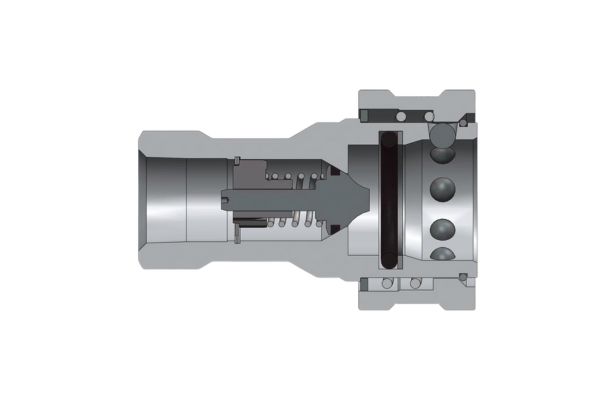
Trapped pressure is the invisible barrier responsible for the majority of quick coupling connection issues. To understand why it has such a powerful effect, one must consider basic hydraulic principles. The force exerted by trapped fluid is calculated as Pressure multiplied by Area (F=P*A). The area is the cross-section of the coupling’s internal valve. Even a modest pressure of 500 PSI, which can easily be generated by thermal expansion, acting on a valve with a surface area of just 0.5 square inches, creates 250 pounds of resistive force. This is far more than an operator can overcome manually. This pressure lock typically originates from two distinct sources:
1. Residual System Pressure
This occurs when a hydraulic circuit is actuated while the lines are disconnected. The control valve sends pressurized fluid down the line, but with nowhere to go, it becomes trapped between the valve and the quick coupling half. The check valve inside the coupler functions perfectly, holding this pressure indefinitely. The solution is procedural. Before attempting to connect, the machine must be turned off, and the hydraulic control lever for that specific circuit should be moved back and forth through its full range of motion. This action opens a path for the trapped oil to return to the hydraulic reservoir, instantly relieving the pressure.
2. Thermal Expansion Pressure
This phenomenon is common in mobile equipment left outdoors. When a disconnected hose and its attached implement are exposed to direct sunlight, the hydraulic fluid inside warms up. Like all liquids, oil expands when heated. Contained within a sealed hose, this expansion results in a significant pressure increase. An implement disconnected in the cool morning can become impossible to reconnect in the heat of the afternoon. The solution here requires safely relieving this pressure. Many modern tractors and implements have built-in pressure-relief mechanisms on the couplers themselves. If not, the male tip can be carefully pressed against a hard, clean surface (like a block of wood) to briefly open the valve and release a small amount of fluid. It is critical to use a rag to catch the oil and to wear appropriate personal protective equipment (PPE), as the released fluid can be hot and under pressure.
Could Contamination Be Blocking the Connection?
The coupling parts look aligned but feel gritty upon connection and refuse to seat. This resistance hints at an internal obstruction that could score seals and contaminate the entire hydraulic system.
Absolutely. Even microscopic contaminants like dust, grit, or metal shavings can prevent a proper connection. This debris obstructs the precise movement of locking mechanisms and compromises the integrity of sealing surfaces.

The Impact of Foreign Debris
Hydraulic quick couplings are precision-engineered components with tight internal tolerances. Their reliability is contingent on maintaining a clean operating environment, which can be challenging in the dusty and dirty conditions of construction sites and farms. Contamination is the second most common cause of connection failure and a leading cause of long-term component damage.
Types of Contaminants and Their Effects:
- External Debris: Dust, mud, sand, and wood chips are common culprits. When present on the face of a coupler, this debris can be forced into the hydraulic system during connection, leading to premature wear of pumps, valves, and cylinders. It can also become lodged in the locking sleeve of the female coupler, preventing it from moving freely.
- Internal Debris: Small metal shavings from component wear, tiny pieces of old seals, or rust particles can flow through the system and get caught in the small orifices and springs within a quick coupling. This can cause the internal poppet or flat-face valve to stick in a partially open or closed position.
Prevention as the Best Solution:
The most effective strategy against contamination is preventative.
- Use Dust Caps: Always install the protective dust caps on both the male and female halves of a coupler as soon as they are disconnected. We, as a supplier, stress the importance of these seemingly simple accessories because they are the first and most effective line of defense.
- Clean Before Connecting: Before every connection attempt, both halves of the coupling should be thoroughly wiped clean with a lint-free cloth. Pay special attention to the face of the male nipple and the area inside the female sleeve.
- Choose the Right Coupler Type: For applications in particularly dirty environments, ISO 16028 flat-face couplers are a superior choice. Their design presents a smooth, flat surface with no deep recesses, making them exceptionally easy and quick to wipe clean compared to the recessed areas of traditional poppet-style couplers.
| Coupler Type | Contamination Risk | Ease of Cleaning | Primary Weak Point |
| ISO 7241-A (Poppet) | High | Difficult | Recessed poppet area collects dirt. |
| ISO 7241-B (Poppet) | High | Difficult | Deep recesses around the valve. |
| ISO 16028 (Flat Face) | Very Low | Excellent | Smooth, wipeable surface. |
Are You Dealing with Damaged or Worn Components?
Pressure has been relieved and the parts are clean, yet the coupling still binds or leaks. The issue may lie with the physical integrity of the coupling itself, indicating wear or damage.
Yes, physical damage or excessive wear can prevent a proper connection. Dents in the sleeve, worn locking balls, or degraded seals can create mechanical obstructions or misalignments that block a secure fit.
Diagnosing Physical Integrity
When the usual suspects of pressure and contamination have been ruled out, a thorough physical inspection of the coupling components is the next critical step. Couplings used on mobile machinery are subject to harsh conditions and can be easily damaged.
Common Forms of Damage and Wear:
- External Damage: The most obvious form of damage is often external. Dropping a hose on a hard surface or accidentally running over it can dent the female coupler’s retractable sleeve. Even a minor dent can prevent the sleeve from moving smoothly, making connection or disconnection difficult or impossible. The male nipple can also be deformed, preventing it from seating correctly in the female body.
- Brinelling: This is a form of wear that occurs over thousands of connection cycles. The hardened steel locking balls in the female half create small indentations, or “brinells,” on the surface of the male nipple’s locking groove. When these indentations become severe, they create a rough surface that can cause the locking balls to catch, leading to a sticky or difficult connection.
- Seal Degradation: The internal O-rings and seals are made of elastomeric materials that degrade over time, especially with exposure to extreme temperatures, UV light, and aggressive hydraulic fluids. A seal can become hardened, cracked, or swollen. A swollen seal can create significant friction, making it very difficult to insert the male nipple fully.
- Corrosion: In humid or marine environments, or where road salt is used, the steel components of a coupling can corrode. Rust can form on the springs or locking ball mechanism, causing them to seize up and fail to operate correctly. This is why many high-quality couplings, including those we supply, feature enhanced corrosion-resistant plating like Zinc-Nickel.
A careful visual and tactile inspection can reveal most of these issues. Any component showing clear signs of dents, deep scoring, or significant corrosion should be replaced promptly to avoid sudden failure under pressure.
Have You Caused a Partial or False Connection?
The coupling seems to connect, but the hydraulic function is weak or non-existent. This situation can be confusing and dangerous, as the connection is not secure and may be restricting flow.
This indicates a partial or false connection. The locking sleeve may not have fully engaged, leaving the internal valves only partially open, which restricts flow and creates a serious risk of disconnection under pressure.
The Dangers of Incomplete Engagement
A false connection is a hazardous and often misunderstood failure mode. It occurs when the operator believes a connection has been made, but the locking mechanism has not fully and securely engaged. This can happen for several reasons: the operator failed to push the sleeve all the way forward, the sleeve is stuck due to dirt or damage, or there is an internal misalignment.
The Consequences of a False Connection:
- Restricted Flow and Heat Generation: In a partial connection, the internal valves (poppets or flat faces) are only slightly open. This creates a significant restriction, or orifice, in the fluid path. As high-pressure hydraulic fluid is forced through this small opening, its velocity increases dramatically, and the pressure drops. This process generates an immense amount of localized heat, which can quickly degrade the hydraulic fluid and damage the coupler’s internal seals. System performance will be sluggish, and actuators will move slowly or with reduced force.
- The Risk of Violent Disconnection: This is the most severe danger. A partially engaged coupling is not securely locked. When the hydraulic circuit is pressurized, the force can overcome the partially seated locking balls and cause the coupling to fly apart violently. This phenomenon, known as “hydraulic whip,” can cause serious injury to anyone nearby and results in a massive loss of hydraulic fluid.
Ensuring a Full Connection
After making a connection, it is crucial to verify that it is secure.
- Audible and Tactile Click: A properly seating coupler will often produce a satisfying “click” as the locking balls fall into place and the sleeve moves fully forward.
- Visual Inspection: Visually confirm that the sleeve on the female coupler has returned to its fully forward, locked position.
- The “Tug Test”: After connecting, give the hose a firm tug. If the connection is secure, it will not come apart. If it separates, it was a false connection, and the cause must be investigated before re-attempting and pressurizing the system.
Could You Be Using Mismatched Couplings?
Two couplings appear similar in size but will not connect, or connect with extreme force. This incompatibility can damage both components and highlights the lack of universal standardization across all coupling types.
Yes, this is a frequent issue in a global market. Different standards (e.g., ISO-A, ISO-B, European profiles) have subtle dimensional differences that make them physically incompatible, even if they look alike.

The Challenge of Interchangeability
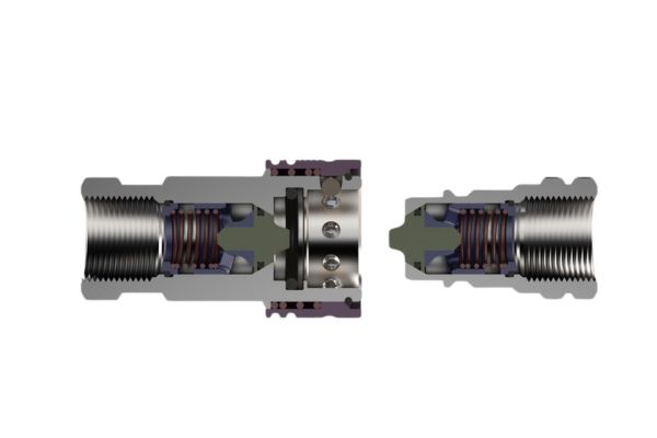
While “quick coupling” sounds like a generic term, it encompasses a wide variety of designs and standards that are not interchangeable. This is a common point of failure for our clients who source machinery and attachments from different regions of the world. An implement from Europe may not connect to a tractor purchased in North America without an adapter. Attempting to force a connection between mismatched standards will damage the components and will never create a safe, reliable seal.
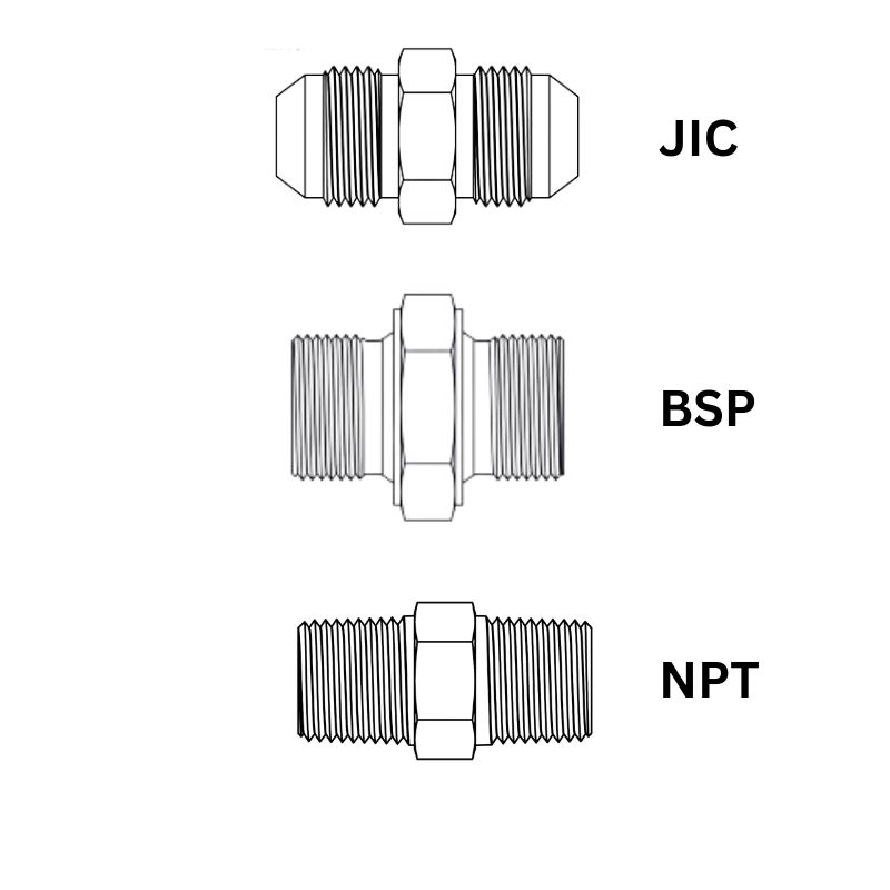
Key Hydraulic Coupling Standards:
- ISO 7241-A: This is a very common poppet-style standard, often referred to as the “AG” standard for its prevalence in agriculture. It has a distinctive poppet supported by a three-legged retaining ring.
- ISO 7241-B: Primarily an industrial poppet-style standard, common in the United States. It is dimensionally different from ISO-A and they will not interchange.
- ISO 16028: This is the international standard for flat-face, no-drip couplers. It is the modern choice for construction equipment and applications where preventing spills and contamination is critical.
- ISO 5675: An older agricultural ball-seat standard that is still present on legacy equipment.
- Proprietary Designs: Many manufacturers have also developed their own specific coupling designs, which will only mate with their own corresponding parts.
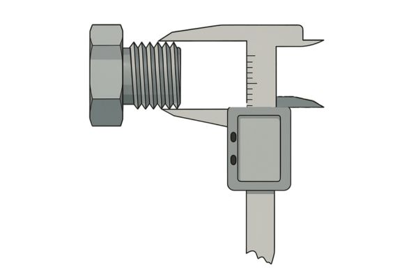
How to Identify Your Coupling:
Identifying the standard is crucial before ordering a replacement.
- Look for Markings: Many couplings are stamped or etched with the manufacturer’s name, a part number, or the standard (e.g., “ISO 16028”).
- Measure Critical Dimensions: Using calipers, measure the diameter of the male nipple tip and the diameter of the female sleeve. These measurements can be compared against technical data sheets.
- Inspect the Profile: Look closely at the shape of the male nipple’s tip and the design of the internal poppet. The visual differences can be subtle but are a key identifier.
| Standard | Sealing Type | Primary Application | Key Visual ID | Not Interchangeable With |
| ISO 7241-A | Poppet | Agriculture, General | Poppet with 3-leg support | ISO-B, ISO 5675 |
| ISO 7241-B | Poppet | US Industrial | Poppet with winged support | ISO-A, ISO 5675 |
| ISO 16028 | Flat Face | Construction, High-End | Smooth, flat mating surface | All poppet types |
When in doubt, sending clear photographs and measurements to a knowledgeable supplier like us is the surest way to get a positive identification and the correct replacement part.
Does Temperature Affect the Coupling Connection?
On a very cold morning, a clean and depressurized coupling is extremely stiff and difficult to connect. This stiffness, not present in warmer weather, suggests a temperature-related material issue.
Yes, extreme temperatures directly impact connections. Severe cold makes seals hard and less pliable, while also increasing oil viscosity, making internal valves sluggish and connection physically harder.
The Influence of Thermal Dynamics
Temperature plays a dual role in coupling performance, with both heat and cold presenting unique challenges. While thermal expansion creating pressure is a common issue related to heat, extreme cold introduces a different set of physical problems that can hinder a smooth connection.
The Effects of Extreme Cold:
- Seal Stiffening: Most standard hydraulic seals are made from Nitrile (NBR). As temperatures approach and fall below freezing (0°C / 32°F), Nitrile becomes progressively harder and less flexible. A stiff, unpliable seal creates significantly more friction, making it very difficult to insert the male nipple into the female body. The seal may also fail to seat correctly, leading to leaks once the system warms up. For applications in consistently frigid climates, we supply couplers with low-temperature seal materials like special NBR compounds or Viton.
- Increased Oil Viscosity: Hydraulic fluid becomes much thicker in the cold. This high-viscosity oil moves sluggishly and can make the internal valves of the quick coupling difficult to move. The force required to push the poppet or flat-face valve open during connection increases substantially. A slow, gentle warm-up of the hydraulic system before attempting to connect attachments is often the best approach.
- Metal Contraction: While a minor factor compared to seal and oil issues, the metal components of the coupling will contract slightly in extreme cold. This can make the already tight tolerances of the coupling even tighter, adding to the overall resistance during connection.
The Effects of Extreme Heat:
Beyond the pressure-lock issue, very high operating temperatures (above 82°C / 180°F) can cause seals to soften excessively, making them prone to damage, extrusion, or “nibbling” during connection and disconnection. Consistently high operating temperatures indicate a potential problem with the hydraulic system’s cooling capacity and will drastically shorten the life of all seals, not just those in the couplings.
Conclusion
Troubleshooting a stubborn quick coupling follows a logical path: first, verify an absence of pressure. Next, ensure absolute cleanliness. Then, inspect for physical damage and confirm it is a fully engaged, matched pair. If you have a problem with your quick couplings and need to replace them, contact Topa directly, we are always ready to provide you with the best quality products!