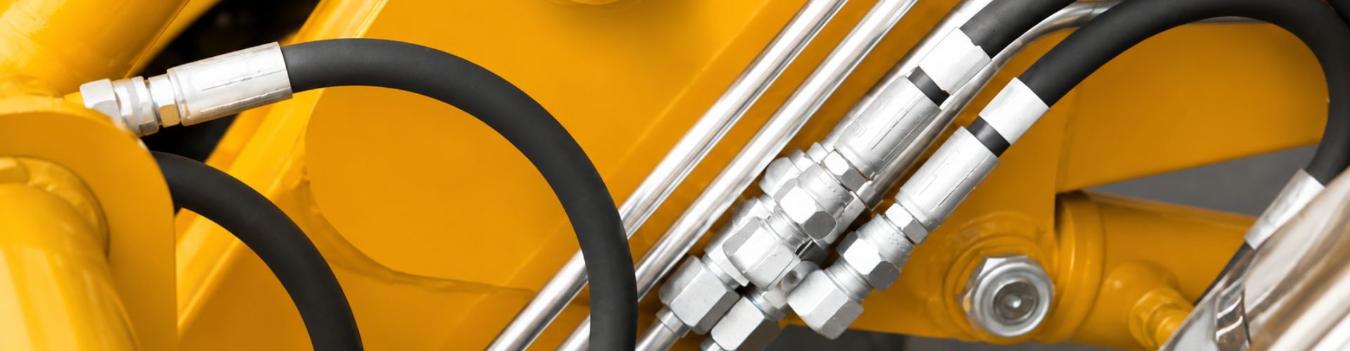
How Is a One-Piece Hydraulic Fitting Pressure Rating Determined

How Is a One-Piece Hydraulic Fitting Pressure Rating Determined?

A fitting pressure rating is determined for an exact design and condition, then limited in use by every component in the connected assembly and circuit. A one-piece hydraulic fitting pressure rating cannot be assigned from the fitting body’s appearance or family name alone. Size, connection, geometry, material, hose, ferrule, crimp specification, adapter, port, seal, temperature, fluid, pressure impulses, spikes, installation, and applicable product data all matter. Working, proof, burst, and impulse conditions describe different questions and must not be exchanged. The usable working limit is no higher than the lowest applicable rating in the complete configuration, under the actual operating and environmental conditions.

What a Fitting Pressure Rating Represents

A published rating applies only within the scope defined by its source. It may be tied to an exact part, size, connection, material, test method, temperature condition, or assembly combination, so the number has no safe meaning when those boundaries are removed.
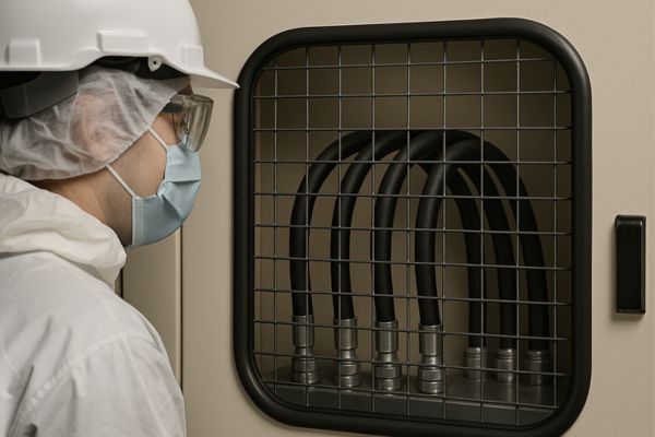
Burst Pressure test

Rating belongs to a defined configuration

Identify the fitting part and revision, connection standard, size, shape, wall geometry, material, finish, and sealing form. An elbow, swivel, flange, or reduced passage may have a different controlling geometry from a straight item in the same series. Do not assume one family has one universal rating or transfer data between sizes.

Published value and usable limit differ

The fitting may have a stated limit, but the connected hose, crimped interface, adapter, port, seal, valve, or equipment requirement may be lower. Temperature, impulse duty, fluid, vibration, corrosion, and installation can add conditions or derating. The system should use the lowest applicable approved limit, not the highest number found in the document set.

Separate Working, Proof, Burst, and Impulse Conditions

These terms are related to pressure evaluation but are not interchangeable operating ratings. Their exact definitions and acceptance criteria must come from the applicable current standard, manufacturer, or equipment data.

Working and proof pressure answer different questions

Working pressure is the approved operating boundary under stated conditions. Proof pressure is generally a controlled verification condition and is not permission to operate continuously at that level. A passed proof event also does not establish unlimited fatigue life, compatibility, or suitability for a different assembly.

Burst and impulse are not working pressure

Burst testing examines failure under a defined increasing-pressure procedure, while impulse testing evaluates repeated pressure cycling under stated conditions. Burst pressure must never be used as normal working pressure. An impulse result must be linked to waveform, temperature, cycle conditions, hose, fitting, crimp, sample identity, failure mode, and acceptance criteria before it supports a decision.

Keep these records separate:

The Complete Assembly Controls the Usable Rating

The hose assembly is a chain of pressure-containing and sealing elements. Its usable limit is controlled by the lowest-rated applicable component and the validity of the exact combination.

Hose and crimp are configuration specific

Matching dash size does not prove that a hose and fitting can be assembled safely. Verify hose manufacturer or accepted specification, series, construction, ID, reinforcement, fitting series, ferrule design, crimping equipment, die set, preparation, insertion, crimp diameter, and inspection procedure. Use current data for the exact combination; an approximate crimp measurement is not approval.

Interfaces can lower the boundary

Adapters, quick couplings, tubes, valves, ports, seals, and equipment connections may have different ratings or conditional limits. A highly rated fitting cannot raise a lower port or hose rating. Likewise, adding an adapter to solve a thread mismatch creates another rated component and sealing interface that must be reviewed.

Size, Material, Connection, and Temperature Matter

Pressure capability can change across sizes and connection forms because geometry, wall sections, stress paths, and sealing designs change. Material and temperature must also be evaluated at the product level rather than through generic assumptions.
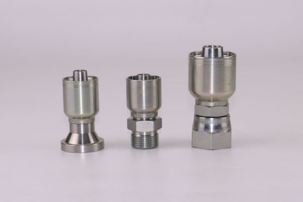
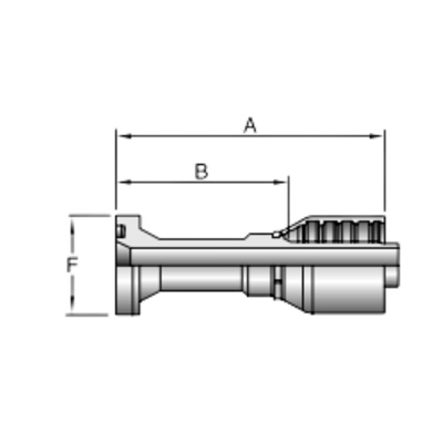
Parker reference Fitting

Size and connection alter the design

Larger or smaller versions do not necessarily scale proportionally. Threads, seats, flange interfaces, bends, swivels, and internal transitions create different critical sections. A visual cross-reference or shared series name cannot establish equivalence; use the exact part’s current pressure data and drawing.

Material and temperature change the condition

Carbon steel, stainless steel, and other materials include different grades and conditions, and none is universally higher rated. Temperature may affect metal properties, O-rings, hose tube and cover, fluid, coating, and crimped behavior. Apply only documented temperature-related limits or derating for the exact component and assembly; do not create a local universal value.

Ports, adapters, and seals also matter because pressure containment and sealing are separate but connected functions. A component may withstand pressure structurally yet leak or become unsuitable because the wrong thread, seat, O-ring, or seal is used.

Confirm connection and sealing identity

Distinguish thread form, diameter, pitch or TPI, straight or tapered form, gender, seat angle, sealing face, and O-ring location. JIC, SAE flare, NPT, NPTF, BSPP, BSPT, ORFS, ORB, metric, and flange systems must not be interchanged by appearance. Thread sealant cannot correct a wrong standard, damaged face, incorrect seat, cross-threading, or wrong port.

Review every pressure boundary

The port may be part of a valve, pump, cylinder, manifold, or adapter with its own material, geometry, condition, and installation procedure. Seals need verified fluid and temperature compatibility as well as correct dimensions and support. Confirm the connected equipment’s rating and assembly instructions rather than assuming a port accepts whatever the fitting can withstand.

Account for Static Pressure, Impulses, and Spikes

A system that normally operates below a stated limit can still impose damaging transient or cyclic loads. Pressure duty should be described over time, not by one steady gauge reading.

Static readings can hide dynamic demand

Valve shifts, load changes, actuator stops, pump behavior, and trapped pressure can create spikes or repeated impulses. The instrument, sampling rate, measurement location, and operating state influence what is observed. Use approved diagnostic methods and equipment data; do not infer that no spike exists because a slow gauge did not display one.

Duty cycle affects validation

Frequent cycling, vibration, temperature changes, and hose movement can make an application more demanding than occasional steady operation. An impulse test report is relevant only when its configuration and conditions support the intended comparison. It does not prove suitability for every machine or authorize operation beyond the approved working limit.

Pressure-duty review should include:

Verify Pressure Suitability Before Use

A documented hierarchy prevents a convenient high number from overriding the actual weakest component. Complete the review before purchasing, assembly, or replacement and repeat it when the configuration changes.

Build the component hierarchy

List the hydraulic fitting, hose, ferrule, crimp data, adapter, coupling, port, valve, tube, cylinder, seals, and equipment limit. Record each source, revision, condition, and any temperature or duty restriction. The selected working boundary is the lowest applicable approved value after all conditions are aligned.

Conflicting documents need resolution rather than selection of the most favorable number. A catalog, drawing, crimp table, test report, and equipment manual may describe different scopes or revisions. Identify which source controls the exact assembly and ask the responsible technical authority to resolve inconsistencies. Preserve the resolution with the part record so receiving and maintenance teams do not recreate the dispute during an urgent replacement.

pressure drop

Validate identity and assembly

Compare purchase description, drawing, markings, labels, and reports with the received components. Confirm critical dimensions, material and finish evidence, hose compatibility, and the approved crimp procedure. A sample result supports only the exact configuration evaluated and should not approve other sizes, shapes, materials, or the entire series.

Installation and inspection also need controlled boundaries. Follow the specified port preparation, seal installation, tightening or assembly procedure, routing, support, and cleanliness requirements. Misalignment, damaged sealing faces, side loading, contamination, or incorrect torque procedures can cause leakage or failure below an otherwise valid component rating. After safe commissioning, inspect according to the equipment plan and investigate abnormal pressure, movement, heat, noise, or leakage without touching an energized line.

Common Pressure-Rating Mistakes

The common errors are using burst as working pressure, assigning one rating to a series, ignoring ports and adapters, and approving a replacement by appearance.

Reject number shopping

Do not choose the largest value from unrelated catalogs, tests, or components. Check what the value means, which configuration it covers, and which conditions apply. Proof, burst, and impulse evidence can support defined evaluations but cannot replace the approved working-pressure limit.

Do not bypass safety for downtime

Never install a mismatched fitting temporarily, reuse a damaged component, or check a pinhole leak by hand. Stop equipment, isolate the hydraulic system, release pressure and stored energy, secure suspended loads, and follow lockout, equipment, hose, and fitting procedures before inspection or replacement.

Conclusion

Pressure suitability is established for an exact configuration and operating condition, not for a fitting family by appearance. Keep working, proof, burst, and impulse information separate, and never use burst pressure as an operating limit. Verify the fitting size, connection, geometry, material, temperature condition, hose, ferrule, crimp, adapters, ports, valves, and seals. Then include spikes, cycling, fluid, vibration, corrosion, routing, and equipment requirements. The lowest applicable approved component or condition controls the usable assembly limit. Before accepting a one-piece hydraulic fitting pressure rating, prepare current part-specific sources, the complete pressure hierarchy, verified assembly instructions, and a traceable duty profile so later substitutions or operating changes trigger review instead of inheriting an unsupported value, and keep that limit visible during maintenance.

FAQ

Does every fitting in one series have the same pressure rating?

No, size, connection, geometry, material, and design can change the rating. Use current data for the exact part and stated condition.

Can burst pressure be divided to estimate working pressure?

Not without an applicable approved rule and product data. Burst and working pressure answer different questions, so a local calculation cannot replace the stated operating limit.

Does a proof test approve repeated operation at proof pressure?

No, a proof test is a controlled verification condition. Repeated operation must remain within the approved working and duty limits for the complete assembly.

Can a higher-rated fitting raise a hose assembly rating?

No, the assembly remains limited by its lowest-rated component and exact combination. Hose, crimp, ports, adapters, seals, temperature, and duty all require verification.

Is a matching thread enough to confirm pressure suitability?

No, thread engagement does not confirm seat, sealing method, material, wall geometry, hose compatibility, crimp data, temperature condition, or pressure rating.
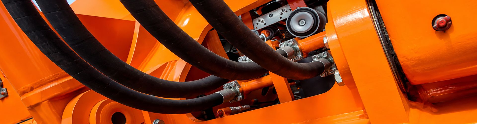
How One-Piece Fitting Internal Bore Affects Hydraulic Flow

How One-Piece Fitting Internal Bore Affects Hydraulic Flow

The internal bore affects hydraulic flow by setting the passage area and shaping local transitions that influence velocity and pressure loss. A one-piece fitting internal bore can be mechanically compatible with a thread and hose yet still be hydraulically restrictive when its effective area, elbow path, or internal step is smaller or sharper than the surrounding circuit. The result may include added pressure drop, heat, slower actuator response, or more demanding inlet conditions, depending on flow, fluid, temperature, and system design. Thread size alone cannot answer the question. Selection requires verified internal geometry and operating data for the hose, port, fitting, adapters, and complete flow path.

Thread Size Does Not Define Flow Area

Connection size identifies an interface, not the smallest usable passage through the fitting. The thread, seat, wall thickness, hose tail, swivel, and manufacturing transitions can leave an internal area that differs from the nominal port or hose size.

16A43 Crimp Hydraulic Hose Fittings Drawing

Find the controlling passage

Review the complete internal path from port entry to hose tail and identify its smallest effective section. A drawing should distinguish thread dimensions from flow dimensions and show whether internal features, seats, steps, or inserts reduce the passage. A single outside measurement or catalog dash number cannot reveal that boundary.

Compare exact configurations

Straight and elbow fittings within one family may not share identical internal geometry, and sizes do not scale in one universal ratio. A replacement should therefore be compared by exact part revision, connection, hose side, and flow drawing. Visual similarity or successful thread engagement proves neither passage area nor hydraulic equivalence.

Manufacturing details also need an appropriate control boundary. Drilling, forming, intersections, and deburring can affect the realized passage, but an article cannot define acceptable variation without a drawing or specification. If bore geometry is a critical characteristic, state where and how it is measured, which revision controls it, and how receiving evidence relates to the delivered lot. A nominal catalog description without a measurement reference is not enough for a pass/fail decision.

Useful data includes:

Bore and Transitions Change Velocity

For a given flow, velocity rises where effective area becomes smaller. Exact evaluation requires verified dimensions and fluid data, but the qualitative rule helps identify where a fitting can become a local restriction.

Area changes create local acceleration

Fluid accelerates into a reduced section and slows as the passage expands. Abrupt contractions or expansions can create greater local loss than gradual transitions. The effect depends on geometry and operating condition, so it should not be estimated from outside diameter or thread size.

Smoothness is not the only criterion

A visually smooth passage can still be too small for the required flow, while a larger passage can weaken an unsuitable design or conflict with sealing geometry. The largest bore is not automatically best. The selected fitting must meet verified mechanical, pressure, connection, and manufacturing requirements as well as the system’s hydraulic targets.

Elbows and Local Geometry Add Loss

Elbows redirect flow and can add local loss through curvature, turns, area changes, and internal features. Two 90-degree fittings with similar external envelopes may have different effective paths, so angle alone does not establish performance.

Bend shape matters

Centerline radius, cross-section, surface condition, entry transition, and downstream recovery influence flow behavior. A compact elbow may solve clearance but create a more restrictive path than a longer arrangement. This tradeoff should be reviewed with verified product data rather than a universal elbow penalty.

Orientation affects system layout

Adding adapters to obtain the needed direction can create more interfaces and restrictions than a suitable angled fitting, but replacing several parts with one elbow is not automatically better. Check installation envelope, hose routing, bend radius, service access, sealing interfaces, and total flow path together.

Restriction Can Contribute to Heat and Performance Problems

Pressure energy lost across a restriction can become heat, but a fitting should not be blamed without system evidence. Pumps, valves, undersized hoses, filters, fluid condition, and control settings may create similar symptoms.

Crimp Fitting dia

Look for system-level consequences

Excessive local loss may reduce available pressure downstream, slow motion, change actuator response, or raise required pump output. In suction or inlet paths, restrictive conditions may contribute to poor filling or cavitation risk. The actual result depends on circuit location, flow, viscosity, temperature, and duty cycle.

Diagnose rather than assume

Compare temperatures and pressures using approved measurement methods at meaningful operating states. Review whether the symptom changes with flow, fluid temperature, or actuator demand. Never touch a suspected hot or leaking component under pressure, and do not replace a fitting with a visually larger passage without confirming all mechanical and safety requirements.

Diagnosis should begin with a safe baseline of the circuit configuration and operating command. A partly closed valve, loaded filter, damaged hose liner, incorrect adapter, or control setting can create a restriction that appears to belong to the fitting. Record measurement locations and instrument condition so readings taken at different points or duties are not compared as equivalents. The purpose is to locate the loss, not to prove a preferred component is responsible.

Hose ID, Port Size, and Bore Work Together

The flow path is only as effective as its combined restrictions. A large hose cannot remove a small port restriction, and a large fitting bore cannot correct an undersized hose or valve passage.

Avoid dash-size shortcuts

Hose dash, port dash, and fitting connection size describe related but different identities. The hose’s actual ID varies by construction and series, while port and fitting passages depend on design. Record each separately so a nominal match does not conceal a smaller effective section.

Review transitions between components

Adapters, reducers, swivel ends, and hose tails can introduce steps even when each component is individually acceptable. Map the installed sequence and check the smallest area, transition quality, number of turns, and cumulative loss. Also verify pressure rating, sealing, torque or assembly procedure, and clearance for every interface.

Routing can change the practical result after a component comparison. A theoretically lower-loss fitting may require a tighter hose bend, extra length, poorer support, or an adapter to fit the available envelope. Those changes may remove the expected benefit or create a different reliability problem. Evaluate the installed option, including motion and service access, rather than ranking isolated fittings on bore size alone.

Review Bore Data Before Selection

A repeatable review starts with operating requirements and ends with a documented comparison of complete configurations. Missing geometry should remain an engineering unknown rather than being replaced with an unsupported flow claim.

Define the required condition

Record normal, minimum, peak, and transient flow conditions; fluid identity and viscosity at relevant temperatures; acceptable pressure loss; circuit location; duty cycle; and performance consequences. Suction, return, pressure, pilot, and drain lines may have different design priorities, so a result from one location should not be transferred automatically.

crimp hydraulic fitting material selection

Obtain configuration-specific evidence

Request a drawing or verified flow-passage data for the exact part and revision. Where quantitative evaluation is required, use an approved engineering method with actual geometry, fluid properties, and operating data. A generic family curve, another size, or an unexplained coefficient should not be treated as proof.

If comparative test data is used, check the test medium, temperature, flow range, pressure measurement locations, setup, specimen identity, and reported uncertainty or limitations. Results from a different port arrangement or hose connection may include losses that are absent from the proposed installation, or omit losses that are present. A plotted curve is useful only when its axes, configuration, and scope are clear enough to support the intended decision.

The review should also consider future operating changes. Higher production demand, a different actuator speed, colder fluid, a revised valve, or added filtration can change the flow condition through the same fitting. Preserve the approved duty and calculation inputs with the component record. When the system changes, revisit the flow path rather than assuming the original conclusion contains unlimited margin.

Review steps include:

Common Bore-Selection Mistakes

Common mistakes include choosing by thread size, assuming larger is always better, comparing outside dimensions, and ignoring cumulative local losses.

Do not confuse mechanical fit with hydraulic fit

A connection can thread correctly and seal while restricting the circuit. Conversely, a generous passage does not approve thread, seat, material, wall strength, or pressure capability. Both hydraulic and mechanical checks must pass for the exact application.

Avoid unsupported calculations

Do not invent bore diameters, flow coefficients, or universal flow limits. Simplified equations can be useful only when their assumptions and inputs match the geometry and flow regime. If verified data is unavailable, state what must be measured or supplied and keep the performance conclusion open.

Neutral Flow-Review Checklist

The final record should make the flow decision reproducible and preserve the separate assembly approvals.

Information to prepare

If the passage data is missing, a sample can be measured under an approved method, but the result should not be generalized to other sizes or revisions.

Keep the approved drawing, measurement record, calculation inputs, and installed configuration together so later purchasing or maintenance changes do not erase the original flow decision.

Conclusion

Internal bore influences flow through its smallest effective area, transitions, turns, and relationship with the surrounding circuit. Thread size, outside appearance, and hose dash cannot define that passage. Map the complete route through ports, adapters, fittings, elbows, and hose; then use verified geometry, flow, fluid, viscosity, temperature, and duty information to evaluate velocity, local loss, heat, and response. The largest bore is not automatically the correct choice because pressure strength, sealing geometry, installation space, and hose compatibility still matter. Before approving a one-piece fitting internal bore for hydraulic flow, prepare exact drawings and system criteria, document unknowns, and complete separate pressure, material, seal, hose, crimp, and safety checks for the selected configuration, and preserve that boundary throughout the equipment lifecycle.

FAQ

Does a larger thread always provide more flow?

No, thread size does not identify the smallest internal passage. Seats, walls, hose tails, swivels, ports, and adapters can control effective flow area.

Are elbow fittings always too restrictive?

No, their effect depends on bend geometry, passage area, flow, fluid, and system criteria. Use verified data for the exact elbow rather than a universal rule.

Can pressure drop be calculated from bore diameter alone?

No, exact evaluation also needs passage length, transitions, turns, surface and flow behavior, fluid properties, temperature, and operating flow.

Can a fitting restriction cause hydraulic heat?

It can contribute because pressure loss can become heat, but other circuit components may be responsible. Diagnose the complete system under approved procedures.

Does a mechanically compatible replacement have the same flow capacity?

Not necessarily. Internal geometry, elbow shape, transitions, hose tail, and passage area may differ even when threads and external dimensions appear to match.

SAE 100R1 vs 100R2 vs 100R16 How to Choose

SAE 100R1 vs 100R2 vs 100R16: How to Choose

Choosing between SAE 100R1 vs 100R2 vs 100R16 requires more than comparing pressure ratings and the number of wire-braid layers. Hose inside diameter, fitting bore, flow rate, temperature, minimum bend radius, pressure impulses, routing, and crimp compatibility all affect system performance.

R1, R2, and R16 Are Not Three Quality Levels

SAE 100R1, SAE 100R2, and SAE 100R16 should not be treated as low-, medium-, and high-quality versions of the same hose.

Each type is designed around a different combination of pressure capability, reinforcement, outside diameter, flexibility, and installation requirements.

SAE 100R1 hydraulic hose Topa

What Is SAE 100R1 Hose?

SAE 100R1 hose typically uses one high-tensile steel wire braid for reinforcement. Many products in this category may also meet corresponding 1SN requirements, but compliance must always be confirmed from the specific hose data sheet.

Its main advantages include:

R1 is often suitable for medium-pressure hydraulic lines when the selected size meets the actual working pressure, surge pressure, temperature, and fluid compatibility requirements.

Its main limitation is that its pressure capability is generally lower than that of a comparable R2 hose. However, when R1 already meets the application requirements, replacing it with a stiffer two-wire hose may provide no practical benefit.

What Is SAE 100R2 Hose?

SAE 100R2 hose typically uses two high-tensile steel wire braids. Many products may also carry a 2SN designation, but the two standards should not be assumed to be identical without product-specific confirmation.

R2 is commonly selected for:

Its advantages include higher pressure capability across many common sizes and increased reinforcement for demanding hydraulic service.

However, R2 is usually heavier and less flexible than R1. This can create installation problems when:

A hose can meet the pressure requirement and still fail prematurely because of mechanical stress.

What Is SAE 100R16 Hose?

SAE 100R16 is generally considered a compact high-pressure hydraulic hose. Depending on the size and construction, it may use one or two wire braids.

R16-high pressure coil hose manufacture in china

Its typical advantages include:

R16 is especially useful where a conventional high-pressure hose cannot be routed naturally without interfering with the frame, guards, moving parts, or adjacent components.

Its compact shape does not make it universally interchangeable with R1 or R2. The selected hose must be assembled with approved fittings, ferrules, and crimp specifications. Crimp dimensions from another hose series should never be copied simply because the outside diameters appear similar.

Why Can a Higher-Pressure Hose Make a Machine Slower?

A higher pressure rating only shows that the hose can withstand a specified pressure under defined conditions.

It does not show how efficiently the hose can carry the required flow.

If a replacement assembly has a smaller effective flow diameter, fluid velocity will increase. Higher velocity can increase pressure loss through the hose, fittings, elbows, adapters, and quick couplings.

The basic relationship is:

Flow rate = Flow area × Fluid velocity

For example, assume a hydraulic circuit carries 60 L/min.

Reducing the effective diameter from 19.0 mm to 12.7 mm more than doubles the fluid velocity.

The actual pressure loss depends on several factors:

The hose series alone does not determine pressure loss. If two assemblies have the same effective inside diameter, fitting bore, length, and routing, choosing a higher-pressure hose does not automatically make the machine slower.

The problem begins when the replacement changes the effective flow path.

How Pressure Loss Becomes Heat

SAE 100R1 hydraulic hoses Topa

Hydraulic power lost across a restriction is converted primarily into heat.

A useful simplified relationship is:

Power loss (kW) = Pressure drop (bar) × Flow rate (L/min) ÷ 600

If a hose assembly carries 60 L/min and produces an 8 bar pressure drop:

8 × 60 ÷ 600 = 0.8 kW

Approximately 0.8 kW of hydraulic power is continuously converted into heat.

If the machine operates for six hours:

0.8 × 6 = 4.8 kWh

That is approximately 4.8 kWh of energy lost through heat generation.

The 8 bar value is only an example. Actual pressure loss must be measured or calculated for the specific hose, fluid, temperature, fittings, and operating conditions.

Installing a larger oil cooler may remove some of the additional heat, but it does not correct the restriction that created the heat.

A Fitting That Screws On May Still Be Too Restrictive

Thread size does not define the complete flow path.

A customer may request:

“One-half-inch hose, BSP fittings on both ends, one metre long, two wire braids.”

This information describes only part of the assembly. It does not confirm that the hose is suitable for the machine.

The following dimensions can be different even when the thread connection is the same:

The smallest internal passage can become the main restriction in the circuit.

For example, a correctly sized hose may still perform poorly if it is connected through:

If one fitting, adapter, or coupling becomes noticeably hotter than the surrounding hose, it may indicate concentrated pressure loss at that location. Temperature alone is not a complete diagnosis, but it is a useful reason to investigate further.

When possible, measure pressure before and after the suspected restriction under the same load, flow, and oil-temperature conditions.

Is a Two-Wire Hose Always Safer Than a One-Wire Hose?

No. If a one-wire hose does not meet the required working pressure or pressure-impulse conditions, a suitable two-wire hose may be necessary.

However, if the selected R1 hose already satisfies the application requirements, installing R2 without checking the routing may introduce new risks.

Increased Side Load on the Port

A stiffer hose resists bending. If the fitting and port are not aligned, the hose may continuously pull against the connection.

This can increase stress on:

Insufficient Installation Space

A larger outside diameter may no longer fit the original clamps, guards, or routing channels.

Forcing the hose into the existing space can cause:

Sharp Bending Behind the Ferrule

The area immediately behind the ferrule should not be forced into a sharp bend.

A hose may have sufficient pressure capacity but still fail near the fitting because of repeated bending, tension, or incorrect routing. Over time, this can contribute to:

The correct decision is not simply “one wire or two wires.”

The correct sequence is:

Pressure, Return, Suction, Drain, and Pilot Lines Need Different Selection Logic

Not every hydraulic line should be selected in the same way.

Hydraulic Hoses structure Topa

Pressure Lines

Pressure lines must withstand normal working pressure, transient pressure, pressure impulses, fluid temperature, and external mechanical loads.

Both pressure rating and flow capacity are important.

Return Lines

Return lines may operate at relatively low average pressure, but they can carry high flow.

An undersized return hose, restrictive fitting, or small quick coupling can create backpressure, heat, seal problems, and reduced actuator performance.

A low pressure reading at the pump does not rule out a return-line restriction.

Suction Lines

Pump suction lines require special attention to vacuum resistance and collapse resistance.

A hose that has a high positive-pressure rating is not automatically suitable for suction service. A hose can be strong under internal pressure but still collapse under vacuum.

Suction applications generally require a hose specifically designed for vacuum or suction conditions.

Case-Drain and Leakage Lines

Hydraulic motor and pump case-drain lines often carry limited flow, but they may be highly sensitive to backpressure.

A restrictive drain hose or fitting can increase housing pressure and contribute to:

Pilot Lines

Pilot circuits may use relatively small hoses, but pressure response and contamination control can be critical. Hose selection must match the control system requirements, not only the thread size.

Three Situations Where You Should Not Order Yet

1. You Know the Thread but Not the Line Function

Knowing that the assembly uses a particular thread does not reveal whether it is a pressure, return, suction, drain, or pilot line.

Identify the function first.

2. You Know the Maximum Pressure but Not the Flow

Pressure determines whether the hose can carry the load safely.

Flow and effective inside diameter influence velocity, pressure loss, and heat generation.

Without flow information, it is difficult to determine whether the selected hose and fittings are large enough.

3. The Hose, Fitting, Ferrule, and Crimp Data Have Not Been Confirmed

A hose assembly is a complete system consisting of:

Components should not be mixed solely because they appear to fit together.

An incorrect crimp may pass an initial visual inspection and remain dry during a short test. It may later fail under pressure impulses, vibration, temperature cycles, or hose movement.

A Practical R1, R2, and R16 Selection Process

Use the following sequence before choosing a hose.

Step 1: Identify the Line Function

Determine whether the hose is used for pressure, return, suction, case drain, pilot control, or another function.

Step 2: Confirm the Fluid

Check compatibility with the hydraulic oil, water-based fluid, biodegradable fluid, or other medium used in the system.

Step 3: Confirm the Temperature

Record both fluid temperature and surrounding temperature. Also check for nearby exhaust components, engines, furnaces, or other heat sources.

Step 4: Record Working and Peak Pressure

Do not select a hose based only on the pressure observed during light operation.

Consider:

Step 5: Determine Continuous and Peak Flow

Use the maximum expected flow for the specific line. Return flow may differ from pump delivery because of cylinder area ratios, accumulators, or combined circuit operation.

Step 6: Select the Required Inside Diameter

Choose the inside diameter according to flow, acceptable velocity, line function, fluid viscosity, and allowable pressure loss.

Do not assume that two hoses with the same thread size have the same internal flow area.

Step 7: Check the Complete Flow Path

Review the bore of every component:

The smallest passage may control the pressure loss.

Step 8: Check Routing and Minimum Bend Radius

Confirm that the hose can follow its natural curve without twisting, stretching, flattening, or bending sharply behind the ferrule.

Step 9: Confirm the Approved Assembly System

Use compatible hose, fittings, ferrules, and crimp specifications. Record the correct crimp diameter and assembly procedure.

Step 10: Verify the Installed Assembly

After installation:

Final Conclusion

The correct hydraulic hose must satisfy more than pressure. It must also provide the required flow, remain compatible with the fluid and temperature, fit the available space, follow the machine’s movement, and use a verified fitting and crimp system.

A hose that does not burst can still be wrong. If it restricts flow, creates backpressure, bends below its minimum radius, or transfers excessive force to the port, it can reduce machine performance and shorten component life.

Frequently Asked Questions

Can R2 Directly Replace R1?

Sometimes, but not automatically. The R2 hose must have the correct inside diameter, pressure rating, temperature range, fluid compatibility, bend radius, fitting system, and routing space. Its additional stiffness and outside diameter may create installation problems.

Can R16 Replace R2?

It may be possible when the selected R16 size meets all pressure, temperature, flow, impulse, and compatibility requirements. The fittings and crimp dimensions must be approved for the selected R16 hose.

Does the Same Thread Size Mean the Same Hose Size?

No. Thread size describes the connection. Hose inside diameter and fitting bore must be checked separately.

Can R2 Be Used as a Suction Hose?

A high positive-pressure rating does not prove that a hose can withstand vacuum without collapsing. Use a hose specifically rated for the required suction conditions.

Why Does a Fitting Become Hotter Than the Hose?

A local temperature increase may indicate concentrated pressure loss caused by a small bore, partial blockage, sharp flow transition, or restrictive coupling. Confirm the cause through inspection and pressure measurements.

Is a Larger Hose Always Better?

No. An unnecessarily large hose increases cost, weight, oil volume, and installation space. The goal is to choose a size that provides acceptable velocity and pressure loss while meeting all mechanical and safety requirements.

How to Size a Hydraulic Cylinder A Complete Calculation Guide

How to Size a Hydraulic Cylinder: A Complete Calculation Guide

Hydraulic cylinder sizing should not begin with the question, “What bore size should I use?” The first question is: How much force must the cylinder produce under actual operating conditions?

A cylinder that looks adequate on paper may still fail to move the load if the calculation ignores return-line backpressure, friction, acceleration, pressure loss or side loading. An oversized cylinder can also create problems by increasing oil consumption, installation space, moving mass and system cost.

Why a 40 mm Cylinder at 160 Bar Cannot Push an 8-Ton Load

Construction Equipment hydraulic Cylinder

Consider a machine fitted with a hydraulic cylinder that has:

The piston area is: A=πD²/4

Where:

A pressure of 160 bar equals 16 MPa. The theoretical extension force is therefore:

F=P*A

F=16,000,000×0.001257≈20,100 N

That is approximately 20.1 kN, or 2.05 metric tons-force.

An 8-ton-force load is approximately: 8,000×9.81≈78,500 N

The cylinder can therefore produce only about one-quarter of the required force—even before accounting for friction, backpressure and pressure losses.

Under ideal conditions, the theoretical bore required to produce 78.5 kN at 160 bar is: D=√4F/πP ≈ 79mm

However, 79 mm is only a theoretical minimum. It is not a final cylinder specification. The actual bore may need to be larger after considering:

Information Required Before Sizing a Hydraulic Cylinder

Collect the operating data before performing any calculations.

Step 1: Calculate the Required Cylinder Force

The cylinder must overcome more than the nominal load. Depending on the application, the total force requirement may include static load, acceleration, friction, backpressure and other external resistance.

Static load

Static load is the primary resistance when acceleration is not considered. Examples include:

For a vertical load: Fg = m × g

Where:

Engineering documents should distinguish between mass and force. For example, 8,000 kg is a mass, while approximately 78.5 kN is its weight under normal gravity.

Acceleration force

When the cylinder must accelerate a moving mass, include the inertial force: Fa = m × a

A short cycle time or rapid acceleration can significantly increase the required force.

Shock loading requires additional evaluation. A sudden stop, collision or rapidly changing load cannot always be represented accurately by a simple constant-acceleration calculation.

Friction and mechanism resistance

Possible sources of resistance include:

Using one fixed friction percentage for every application is unreliable. Whenever possible, use measured values, component data or a calculation based on the actual mechanism.

Return-line backpressure

During extension, pressure in the cap end pushes the piston forward. Pressure in the rod end creates an opposing force.

The approximate net extension force is:Fext = PA × Ap − PB × Aa − Ff

Where:

This equation is more realistic than using only: F = P × A

Backpressure may be created by:

A cylinder may fail to extend even when the cap-end pressure appears high enough if rod-side backpressure has not been included.

Design margin

A design margin may be necessary when the load is uncertain, shock is present or failure would have serious consequences.

There is no single safety factor suitable for every hydraulic cylinder application. The required margin should be based on:

Avoid applying several overlapping allowances for friction, shock and safety without understanding what each one covers.

Step 2: Determine the Actual Available Pressure

The pump pressure rating is not automatically the pressure available at the cylinder.

The actual cylinder inlet pressure may be lower because of:

The relevant value is the pressure available at the cylinder port while the machine is performing the required operation.

Where possible, measure pressure close to both cylinder ports during the actual loaded cycle. Measuring both chambers helps identify whether return-side backpressure is reducing the net force.

It is also important to distinguish between:

Hydraulic hose connection at cylinder

Step 3: Calculate the Required Cylinder Bore

Once the required force and effective pressure are known, calculate the theoretical piston area: A = F / P

Then calculate the bore: D = √(4F / πP)

Where:

Example: 50 kN at 200 bar

Assume the cylinder must produce a theoretical force of 50,000 N and the available pressure is 200 bar.

A pressure of 200 bar equals 20 MPa:

A = 50,000 / 20,000,000 = 0.0025 m2

This equals:

0.0025 m2 = 25 cm2

The theoretical bore is:

D = √[(4 × 0.0025) / π] ≈ 0.0564 m

Therefore, the calculated minimum bore is approximately 56.4 mm.

The next suitable standard bore may be 63 mm, depending on the selected cylinder series.

A 63 mm bore has a piston area of approximately 31.17 cm2. At 200 bar, its theoretical extension force is:

F ≈ 62.3 kN

This value must still be reduced by rod-side backpressure, friction and other system losses.

Why the calculated bore must be checked again

Rounding up to a standard bore does not complete the selection. Verify:

A larger bore increases force but also increases oil consumption and may reduce speed if pump flow remains unchanged.

Standard Bore Does Not Mean Standard Pressure Rating

A 63 mm bore is available in several cylinder families, but bore size alone does not define the product’s pressure capability.

For example:

These standards primarily define mounting dimensions and interchangeability. They do not mean that every cylinder with a listed bore is suitable for the same pressure, mounting load or duty cycle.

Always confirm the specific product’s:

A standard bore should make sourcing and replacement easier, but it does not replace engineering verification.

Step 4: Check Extension and Retraction Separately

A single-rod double-acting cylinder does not have the same effective area in both directions.

Extension Area

During extension, pressure acts on the full piston area:

Ap = πD2 / 4

Ignoring backpressure and friction:

Fext = PA × Ap

Retraction Area

During retraction, the piston rod occupies part of the pressurized area. The effective annular area is:

Aa = π(D2 − d2) / 4

Where:

D is cylinder bore.

d is piston rod diameter.

Ignoring cap-end pressure and friction:

Fret = PB × Aa

Because the annular area is smaller than the full piston area, a single-rod cylinder usually has:

Step 5: Select the Stroke and Check Mounting Geometry

Stroke is the distance the piston travels, but cylinder stroke should not be selected from linear distance alone.

Calculate the required movement

For a direct linear mechanism, confirm:

Additional stroke should not be used as a substitute for proper end cushioning or mechanical stops.

Check linkage geometry

If the cylinder operates a lever, linkage or pivoting arm, calculate stroke from the full mechanism geometry.

The relationship between cylinder travel and machine movement may change throughout the stroke. Measuring only the distance between two approximate mounting positions can result in insufficient travel, overtravel or an incorrect force angle.

Check retracted and extended length

Confirm that:

Where installation length is limited but long travel is required, possible solutions include a telescopic cylinder, a revised mounting position or a redesigned linkage.

Step 6: Select the Piston Rod and Check Buckling

The piston rod must satisfy more than the retraction-force requirement. It may also need to resist:

Hydraulic Cylinder Types Features

Why stroke-to-bore ratio is not enough

Ratios such as stroke divided by bore or stroke divided by rod diameter can be used as early warning indicators. They cannot provide a final buckling decision.

Buckling depends on:

The basic Euler buckling relationship is:

Fcr = π2EI / (KL)2

Where:

The ideal Euler result should not be used directly as the allowable working load. Actual cylinder selection should follow the manufacturer’s rod selection chart or an approved engineering calculation that includes the required safety margin.

Ways to improve buckling resistance

If the calculated rod capacity is insufficient, consider:

A larger bore alone does not guarantee that the piston rod is safe.

Step 7: Calculate Cylinder Speed and Required Flow

Cylinder speed is determined by flow and effective area:

Q = A × v

Using common hydraulic units:

Q (L/min) = A (cm2) × v (cm/s) × 0.06

Example: 63 mm Bore at 200 mm/s

A 63 mm bore has a piston area of approximately 31.17 cm2.

If the required extension speed is 200 mm/s, or 20 cm/s:

Q = 31.17 × 20 × 0.06

Q ≈ 37.4 L/min

The cylinder therefore requires approximately 37.4 L/min of theoretical cap-end inlet flow.

Actual system flow may need to account for:

Calculate all four flow conditions

A complete calculation should include:

Return flow can be higher than pump inlet flow because the two cylinder chambers have different areas.

If the valve and return piping are selected only from pump flow, the system may develop excessive backpressure, heat and speed loss.

Do not select a valve from nominal flow alone

Check the valve’s pressure-drop-versus-flow curve under the relevant oil viscosity and temperature.

Valve selection should consider:

High pressure loss wastes energy as heat and also reduces the pressure available to move the load.

Step 8: Check Seals, Temperature and Duty Cycle

A hydraulic cylinder that meets the force and speed requirements can still fail early if its materials and seals do not match the application.

Fluid compatibility

Specify the hydraulic fluid, such as:

Seal compatibility should be confirmed for the exact fluid and temperature range.

Operating temperature

Temperature affects:

The cylinder should be checked for both cold start and maximum stabilized operating temperature.

Duty cycle

A cylinder operating several times per day has different requirements from one cycling continuously in an automated production line.

Provide the supplier with:

Cushioning

A fast-moving cylinder may contain significant kinetic energy near the end of its stroke.

Without suitable deceleration, the system may experience:

Depending on the application, the solution may include cylinder cushioning, external flow control, proportional control or mechanical deceleration.

Common Hydraulic Cylinder Sizing Mistakes

Using pump nameplate pressure

Pump rated pressure does not equal the actual pressure available at the cylinder. Use the pressure measured or calculated at the actuator during the loaded operation.

Hydraulic Cylinder in mining

Ignoring return backpressure

Rod-side backpressure reduces extension force. Check the return valve, filter, hoses, piping and any counterbalance or flow-control valves.

Calculating extension only

A cylinder may have enough extension force but insufficient retraction force. Calculate both directions separately.

Assuming a larger bore is always safer

A larger bore increases force, but it also increases:

The correct bore is the one that meets the force requirement while remaining compatible with pressure, flow, speed and installation constraints.

Ignoring piston rod buckling

Long-stroke cylinders under compression require a proper rod stability check. Bore size alone does not determine buckling resistance.

Allowing the cylinder to carry side load

Hydraulic cylinders are designed primarily for axial loading. The machine structure should provide the required external guidance.

Selecting valves from rated flow only

A valve may pass the required flow but create excessive pressure loss. Check the manufacturer’s pressure-drop curve.

Ignoring temperature and duty cycle

High temperature and continuous cycling can increase leakage, reduce viscosity and shorten seal life. Provide realistic operating conditions when specifying the cylinder.

Conclusion

Before ordering a standard or custom hydraulic cylinder, prepare a complete application data sheet covering load, actual pressure, backpressure, stroke, speed, mounting and operating environment. The final specification should then be reviewed against the selected manufacturer’s cylinder data and application limits.

Frequently Asked Questions

What bore is required to produce 8 tons at 160 bar?

Under ideal conditions, 8 metric tons-force is approximately 78.5 kN. At 160 bar, the theoretical minimum bore is about 79 mm.

The final bore will normally need to be larger after accounting for backpressure, friction, dynamic loading, pressure losses and the required design margin.

What safety factor should be used for a hydraulic cylinder?

There is no universal value for every application. The appropriate margin depends on load uncertainty, shock, mounting, duty cycle, applicable standards and the consequences of failure.

Safety-critical lifting or personnel-related equipment requires formal engineering and compliance with applicable regulations.

Is a larger hydraulic cylinder bore always better?

No. A larger bore produces more force but requires more oil flow, occupies more space and may reduce speed. It can also increase cost and return-line flow.

Why is cylinder retraction force lower than extension force?

During retraction, the piston rod reduces the effective pressure area. The resulting annular area is smaller than the full piston area used during extension.

How can piston rod buckling be prevented?

Check rod diameter, effective compression length, mounting constraints and maximum load. Possible solutions include a larger rod, a different mounting style, a stop tube, improved external guidance or a larger cylinder series.

Can a smaller cylinder solve a low-speed problem?

A smaller bore moves faster at the same flow, but it also produces less force. Changing bore size requires a complete force, pressure, rod and stability review.

Contact Topa

Save 30% on maintenance costs with our easy-install hydraulic fittings. Contact Now!