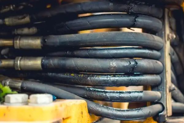
In high-pressure industrial settings, hydraulic oil leaks remain a major issue, causing 70% of system failures and significant financial loss. Conventional maintenance—replacing seals and tightening hydraulic fittings—often falls short, as hidden design flaws go unaddressed. These flaws lead to recurring leaks, safety risks, environmental harm, and costly downtime. Only by targeting the root design issues can facilities achieve lasting reliability and reduce the ongoing burden of hydraulic failures.
I. The Microscopic Precision Gap: Seal Groove Design Flaws
At the heart of many hydraulic oil containment failures lies an easily overlooked detail: the precision of seal groove dimensions. These seemingly minor design elements play an outsized role in system reliability, yet they frequently receive insufficient attention during the design phase.
The Critical Tolerance Factor
The relationship between hydraulic cylinder seal groove tolerance specifications and leak prevention is more critical than engineers often realize. In high-pressure hydraulic systems, even microscopic deviations can create significant problems. Consider a real-world case from a manufacturing facility where a hydraulic cylinder experienced persistent leakage despite multiple seal replacements. Upon detailed investigation, engineers discovered that the seal groove axial tolerance exceeded specifications by merely 0.1mm—a deviation invisible to the naked eye. This minor imperfection caused the O-ring to experience uneven compression under 21MPa pressure, resulting in side extrusion and a substantial leak rate of 0.8L/min.
Surface Finish: The Invisible Leak Path
Beyond dimensional accuracy, surface roughness represents another crucial factor in hydraulic oil containment that often escapes proper scrutiny. Research demonstrates that when surface roughness exceeds Ra1.6μm, seal contact stress distribution uniformity decreases by approximately 42%, creating microscopic channels through which pressurized fluid can escape.
These findings highlight the importance of hydraulic seal surface roughness requirements in preventing oil leakage. Modern hydraulic systems operating at pressures above 20MPa require surface finishes of Ra≤0.4μm on sealing surfaces to ensure reliable containment. This level of finish eliminates the microscopic valleys that can form potential leak paths under pressure.
Advanced Solutions for Precision Sealing
Preventing hydraulic oil leaks with FEA optimization has emerged as a best practice among leading equipment manufacturers. Finite element analysis allows engineers to simulate seal behavior under various pressure conditions, optimizing compression ratios between 15-25% to balance sealing effectiveness against excessive compression that could damage the seal material.
Implementation of these precision-focused approaches requires attention to both design and manufacturing processes:
- Utilize computational modeling to determine optimal groove dimensions based on specific seal materials and operating conditions
- Implement hard anodizing treatments on aluminum components to achieve surface hardness above 60 HRC while maintaining precise dimensions
- Establish rigorous quality control protocols that verify both dimensional accuracy (±0.05mm) and surface finish (Ra≤0.4μm) before assembly
- Document seal groove specifications comprehensively in engineering drawings, including not just dimensions but also surface finish requirements
By addressing these microscopic details during the design phase, manufacturers can eliminate a significant percentage of hydraulic oil leaks before equipment ever reaches the field.
II. Vibration-Induced Hydraulic Connection Failures
While static design elements like seal grooves form the foundation of leak prevention, dynamic factors—particularly vibration—represent another hidden cause of hydraulic oil leaks that frequently escapes proper consideration during system design.
The Resonance Effect on Hydraulic Fittings
Vibration-induced hydraulic fitting leakage occurs when mechanical oscillations gradually loosen threaded connections or create fatigue in components. This phenomenon becomes particularly problematic when the natural frequency of hydraulic components aligns with the operating frequency of nearby equipment, creating a resonance that amplifies vibration effects.
A revealing case study comes from a construction equipment manufacturer where a loader experienced persistent leakage from pump suction line fittings. Detailed frequency analysis revealed that the suction line had a natural frequency of 87Hz—almost perfectly matching the engine’s vibration frequency at certain RPMs. This resonance created vibration acceleration peaks exceeding 8g (well above the 5g industry standard limit), resulting in connection loosening and an annual oil loss of 3.2L from a single fitting.
Pipeline Layout Design Considerations
Optimal hydraulic hose routing to prevent leaks requires thoughtful three-dimensional planning that goes beyond simply connecting points A and B. Modern design approaches utilize topological optimization software to determine ideal routing paths that minimize stress concentrations and vibration effects.
A key consideration in this process is reducing the number of 90° bends, which not only create pressure drop but also serve as stress concentration points where vibration effects are amplified. Each 90° bend eliminated from a hydraulic line design reduces potential leak points and improves overall system reliability.
Vibration Dampening Strategies
Implementing effective hydraulic system vibration dampening solutions requires a multi-faceted approach. Strategic installation of hydraulic accumulators (sized at approximately 1:10 ratio to system volume) helps absorb pressure pulsations that contribute to vibration. Meanwhile, composite rubber-metal mounting brackets provide isolation between hydraulic components and vibration sources.
Advanced vibration mitigation approaches include:
- Conducting modal analysis during design to identify and address potential resonance issues
- Installing flexible hose sections at strategic points to decouple rigid components
- Implementing pulsation dampeners specifically sized for the system’s flow rate and pressure
- Utilizing vibration-resistant thread-locking compounds on critical connections
These measures collectively create a more stable hydraulic system environment, significantly reducing the likelihood of vibration-induced oil leaks throughout the equipment’s service life.
III. Thermal Management Deficiencies
Temperature control represents the third hidden cause of hydraulic oil leaks, with thermal effects often overlooked during system design despite their profound impact on seal performance and system integrity.
The Temperature-Seal Degradation Relationship
Understanding temperature effects on hydraulic oil seal lifespan is crucial for designing leak-resistant systems. Research consistently demonstrates that elevated temperatures accelerate chemical degradation in elastomeric seal materials. The industry rule of thumb—that seal life decreases by half for every 10°C increase above 65°C—has significant implications for system design.
This temperature sensitivity varies by material. Nitrile rubber (NBR) seals, commonly used in hydraulic systems, experience dramatically accelerated aging at elevated temperatures. At 90°C, NBR seals may age eight times faster than at normal operating temperatures, rapidly losing elasticity and sealing capability.
Case Analysis: Extreme Temperature Consequences
A compelling example of high-temperature hydraulic oil leak prevention failure comes from a 4000T injection molding machine that experienced persistent leakage issues. Investigation revealed oil temperatures reaching 92°C during extended operation—well beyond the recommended maximum of 65°C. This thermal stress caused the NBR seals to deteriorate from their original hardness of 70±5 Shore A to just 52 Shore A, with compression set increasing to 38% (far exceeding the 25% maximum allowable limit).
The consequences extended beyond just fluid loss. The degraded seals allowed contaminants to enter the system, accelerating wear on precision components and creating a cascade of reliability issues throughout the hydraulic system.
“What makes thermal degradation particularly insidious is its gradual nature,” explains maintenance engineer Carlos Mendez. “Unlike a sudden failure, temperature-induced seal degradation happens incrementally over weeks or months, making it difficult to connect cause and effect without careful monitoring and analysis.”
Cooling System Design Innovations
Effective hydraulic oil cooling system design for leak prevention requires moving beyond simplistic approaches to implement targeted cooling strategies. Modern systems increasingly utilize plate heat exchangers with heat transfer coefficients of 3000W/m²·K or greater, providing efficient cooling even in compact installations.
Innovative tank designs represent another advancement in thermal management. Dual-layer spiral flow configurations guide oil through optimized cooling paths, increasing heat dissipation by up to 65% compared to conventional tank designs. These improvements maintain lower average oil temperatures, significantly extending seal life and reducing leak potential.
Implementation considerations for effective thermal management include:
- Sizing cooling capacity for worst-case ambient conditions rather than typical operating environments
- Positioning temperature sensors at multiple points to identify localized hot spots
- Implementing temperature-triggered variable-speed cooling fans for energy-efficient operation
- Considering closed-loop water cooling for high-heat applications where air cooling is insufficient
By addressing thermal management as a critical design factor rather than an afterthought, engineers can significantly extend seal life and reduce the incidence of temperature-related hydraulic oil leaks.
IV. Connection and Thread Design Inadequacies
The fourth hidden cause of hydraulic leakage lies in connection and thread design choices that may seem minor but have outsized impacts on system integrity.
The Fitting Selection Dilemma
Developing a comprehensive pressure-rated hydraulic fitting selection guide is essential for system designers, as different fitting types offer varying pressure capabilities and reliability characteristics. The selection process must account for not just maximum pressure ratings but also pressure cycling, vibration exposure, and temperature fluctuations.
Common fitting types and their characteristics include:
- JIC 37° flare fittings: Good for medium pressure applications up to 350 bar, but susceptible to vibration loosening
- ORFS (O-ring face seal): Excellent for high-pressure, high-vibration environments up to 420 bar
- NPT/BSPT tapered thread: Economical but requires careful installation and proper sealant application
- Welded connections: Maximum reliability for permanent installations, but no serviceability
The Torque Factor in Hydraulic Connections
Understanding hydraulic fitting torque specifications to prevent leaks is crucial yet frequently overlooked. The relationship between applied torque and sealing effectiveness follows a bell curve rather than a linear progression—both insufficient and excessive torque lead to leakage.
A revealing case study comes from an excavator hydraulic pump that experienced persistent leakage from an NPT threaded connection. Analysis showed the connection had been overtightened by approximately 20%, creating distortion in the sealing surfaces that reduced contact stress by 40%. This seemingly minor installation error resulted in a persistent leak that eluded multiple repair attempts.
“The misconception that ‘tighter is better’ causes countless hydraulic leaks,” explains maintenance trainer Sarah Johnson. “Proper torque creates optimal stress distribution across sealing surfaces. Exceed that torque, and you’re actually reducing sealing effectiveness while potentially damaging components.”
Advanced Connection Technologies
Implementing advanced hydraulic connection systems for zero-leak performance requires moving beyond conventional fittings to embrace newer technologies specifically designed for challenging applications. Composite sealing systems that combine 24° cone faces with supplementary O-rings provide redundant sealing mechanisms that maintain integrity even under extreme conditions.
Installation practices are equally important, with digital torque tools now considered essential for critical connections. These tools provide precise torque application with ±3% accuracy and maintain records of installation parameters for quality assurance purposes.
Forward-thinking organizations are implementing comprehensive connection management protocols that include:
- Standardized torque specifications documented for all connection types and sizes
- Training programs that emphasize proper installation techniques
- Quality control processes that verify connection integrity before system commissioning
- Traceability systems that document who installed each critical connection and when
These measures collectively address the connection-related factors that contribute to hydraulic oil leaks, creating more reliable systems with significantly reduced maintenance requirements.
V. Material Compatibility Oversights
The fifth and final hidden cause of hydraulic leakage involves material compatibility issues—particularly between seals and hydraulic fluids—that can undermine even the most carefully designed systems.
Chemical Interaction Between Seals and Fluids
Implementing thorough hydraulic seal material compatibility testing is essential yet frequently overlooked during system design. The chemical interaction between elastomeric seals and hydraulic fluids is complex, with factors including temperature, pressure, and fluid additives all influencing compatibility.
These interactions can manifest in several ways:
- Swelling: Absorption of fluid components causes dimensional changes that alter seal fit
- Shrinkage: Extraction of plasticizers from the seal material leads to hardening and reduced sealing ability
- Chemical degradation: Reactions between fluid additives and seal materials break down the elastomer structure
- Physical degradation: Fluid flow across seal surfaces causes erosion and mechanical damage
Real-World Failure Analysis
A compelling example of biodegradable hydraulic oil leak problems comes from a marine hydraulic system that experienced catastrophic seal failures shortly after switching to an environmentally friendly hydraulic fluid. Investigation revealed that while the FKM (fluorocarbon) seals used throughout the system were generally considered compatible with the new fluid, they experienced excessive swelling—28% volumetric expansion compared to the 15% maximum allowable limit.
This swelling altered the seals’ mechanical properties and fit within their grooves, ultimately leading to seal lip tearing and significant leakage. The case highlights how even seemingly appropriate material combinations can fail when subjected to real-world operating conditions.
Material Selection and Validation Protocols
Developing effective hydraulic seal material selection for extreme environments requires a systematic approach that considers all operating parameters. Best practices include:
- Conducting accelerated aging tests that subject seal materials to elevated temperatures (typically 85°C) in the actual hydraulic fluid for extended periods (minimum 500 hours)
- Measuring critical parameters before and after testing, including hardness, tensile strength, and volumetric change (which should remain within ±5%)
- Creating application-specific material selection matrices that account for temperature range, pressure, fluid type, and environmental exposure
- Maintaining detailed documentation of material compatibility testing results for future reference
Conclusion
The payoff is substantial: reducing oil loss by up to 50%, cutting downtime, boosting safety, and enhancing sustainability. As system demands rise, only proactive, design-driven strategies will ensure long-term reliability and performance.
FAQ
What are the common causes of hydraulic fluid leaks?
Common causes include damaged seals, loose fittings, aging lines, design flaws, vibration effects and thermal expansion.
What are the effects of hydraulic fluid leakage?
Leaks can lead to reduced equipment efficiency, environmental contamination, safety hazards, increased maintenance costs and unplanned downtime.
How can I quickly recognize if there is a leak in my hydraulic system?
Check for oil stains around the equipment, a drop in hydraulic fluid level, abnormal system pressure, or unusual noises and performance degradation.
Can a hydraulic fluid leak be repaired on its own?
Small leaks can be temporarily repaired by replacing seals or tightening fittings, but a professional should check and treat the underlying problem.
How to prevent hydraulic oil leaks?
Ensure proper construction at the design stage, use compatible materials, maintain good assembly accuracy, and regularly maintain and inspect the system.
Is hydraulic oil leakage a normal wear phenomenon?
No, it is not. Although the system will age, persistent or frequent leaks are usually the result of poor design or maintenance and should be dealt with promptly.