Hydraulic system performance critically depends on hose diameter selection, yet many engineers rely on rules of thumb rather than systematic analysis. Incorrect sizing leads to serious consequences: undersized hoses cause flow restriction, pressure drops, and heat generation leading to premature failure; oversized hoses waste space, add weight, increase costs, and may reduce responsiveness. This article demystifies hydraulic hose diameter selection by exploring fundamental relationships between diameter, flow, and flow rate.
Understanding the Relationship Between Diameter, Flow, and Flow Rate
A. Fundamental Concepts
To properly select hydraulic hose diameters, we must first understand the distinction between flow and flow rate, and how these parameters relate to hose diameter.
Flow refers to the volume of fluid moving through a system per unit of time, typically measured in gallons per minute (GPM) or liters per minute (LPM). This is the parameter that determines how quickly actuators move and how much power can be transmitted through the system.
Flow rate, on the other hand, refers to the velocity at which fluid travels through the system, typically measured in feet per second (ft/s) or meters per second (m/s). This parameter affects pressure drop, heat generation, and system responsiveness.
The relationship between these parameters is governed by the continuity equation:
Q = V × A
Where:
- Q = Flow (volume per time)
- V = Velocity (distance per time)
- A = Cross-sectional area of the hose
This equation reveals the inverse relationship between cross-sectional area and fluid velocity: for a given flow volume, as the hose diameter (and thus area) decreases, the fluid velocity must increase proportionally. Conversely, increasing the hose diameter reduces fluid velocity.
To visualize this concept, imagine water flowing through garden hoses of different diameters. When the same volume of water flows through a narrow hose, it moves much faster than when flowing through a wider hose. This same principle applies to hydraulic systems, though with much higher pressures and more significant consequences.
B. Impact on System Performance
The diameter-flow-velocity relationship has several critical implications for hydraulic system performance:
Pressure Loss: As fluid moves through a hose, it experiences resistance due to friction against the hose walls. This friction creates pressure drop, which is proportional to the square of the fluid velocity. Therefore, doubling the fluid velocity quadruples the pressure drop. Since smaller diameters increase velocity, they dramatically increase pressure losses.
The relationship can be expressed using the Darcy-Weisbach equation:
ΔP = (f × L × ρ × V²) / (2 × D)
Where:
- ΔP = Pressure drop
- f = Friction factor
- L = Hose length
- ρ = Fluid density
- V = Fluid velocity
- D = Hose internal diameter
Fluid Friction and Heat Generation: The friction that causes pressure drop also generates heat. In fact, all pressure losses in a hydraulic system eventually convert to heat. Excessive heat degrades hydraulic fluid, damages seals, and reduces component life. Systems with undersized hoses often require larger oil coolers to manage this additional heat.
Energy Efficiency: Pressure losses represent wasted energy. In high-pressure systems, these losses can be substantial, requiring larger pumps and motors and consuming more power. For example, a system operating at 3000 PSI with a 5% pressure loss due to undersized hoses wastes 150 PSI worth of energy—energy that’s converted to unwanted heat rather than useful work.
System Response: While smaller hoses increase fluid velocity, which might seem beneficial for system responsiveness, the associated pressure drops can actually degrade response time by reducing the effective pressure available at actuators. Finding the optimal diameter involves balancing these competing factors.
Factors Influencing Hydraulic Hose Diameter Selection
A. System Requirements
Selecting the appropriate hydraulic hose diameter begins with a thorough understanding of system requirements:
Flow Volume Demands: The primary consideration is how much fluid must move through the system to meet performance requirements. This is determined by:
- Actuator sizes and required speeds
- Pump output capacity
- Cycle time requirements
- Multiple simultaneous operations
For example, a hydraulic cylinder with a 4-inch bore and 24-inch stroke that must extend in 10 seconds requires approximately 12.5 GPM. This flow requirement forms the foundation of hose diameter selection.
Operating Pressure Considerations: System pressure affects hose selection in several ways:
- Higher pressures require hoses with thicker walls, reducing internal diameter
- Pressure spikes must be accounted for, not just nominal pressure
- Pressure drops become more significant as a percentage of total system pressure
A system operating at 5000 PSI has less tolerance for pressure drops than one operating at 1000 PSI, potentially justifying larger diameter hoses despite the added cost.
Duty Cycle and Peak Demand Analysis: Many hydraulic systems don’t operate continuously at maximum capacity:
- Intermittent high-flow operations may tolerate higher velocities
- Continuous operation requires more conservative velocity limits
- Peak demands must be accommodated without excessive pressure drops
A concrete pump truck, for example, might have brief periods of maximum flow separated by longer periods of lower demand, allowing for different sizing considerations than a continuously operating hydraulic press.
Response Time Requirements: Some applications prioritize rapid system response:
- Mobile equipment often requires quick directional changes
- Safety-critical systems may need minimal response delay
- Precise positioning applications require predictable response
These requirements might justify accepting higher fluid velocities in certain circuit sections to minimize response time.
B. Physical Constraints
Real-world applications rarely allow for theoretically optimal hose sizing due to various physical constraints:
Installation Space Limitations: Equipment design often restricts available space for hydraulic hoses:
- Engine compartments in mobile equipment
- Robotic arms with multiple actuators
- Compact machinery with dense component packaging
- Articulating mechanisms with moving connection points
These constraints may force the use of smaller hoses than would be ideal from a purely hydraulic perspective.
Bend Radius Considerations: Larger diameter hoses have larger minimum bend radii:
- A 1/2″ hose might have a minimum bend radius of 5″
- A 1″ hose might require 8″ or more
- Exceeding minimum bend radius reduces hose life dramatically
In tight installations, this factor alone may limit maximum practical hose size.
Weight Considerations for Mobile Applications: Larger hoses and the additional fluid they contain add weight:
- Aerial platforms where every pound matters
- Aircraft hydraulic systems with strict weight limits
- Handheld hydraulic tools where operator fatigue is a concern
In these applications, the performance benefits of larger hoses must be weighed against weight penalties.
Routing Challenges and Solutions: Hose routing must account for:
- Movement between connected components
- Protection from external damage
- Heat sources and potential chafing points
- Accessibility for maintenance
These factors may necessitate multiple shorter hoses with fittings rather than single longer runs, affecting overall diameter selection due to the additional pressure drops at connections.
C. Economic Considerations
Hydraulic hose diameter selection also involves important economic tradeoffs:
Initial Cost vs. Long-Term Efficiency: Larger diameter hoses and fittings cost more initially:
- A 1″ hose assembly might cost twice as much as a 3/4″ assembly
- Fittings for larger hoses are proportionally more expensive
- Installation may be more complex and time-consuming
However, these higher initial costs must be weighed against long-term efficiency gains and reduced operating costs.
Energy Consumption Implications: Undersized hoses increase energy consumption:
- Additional pressure drops require more pump power
- Heat generation necessitates cooling systems that consume power
- For continuously operating systems, these costs accumulate significantly
A 100 HP hydraulic system operating continuously with 5% avoidable pressure loss wastes approximately 5 HP—equivalent to over 30,000 kWh annually.
Maintenance and Replacement Factors: Hose diameter affects maintenance costs:
- Higher fluid velocities accelerate wear, particularly at bends
- Excessive heat degrades fluid, requiring more frequent changes
- Component life is reduced when operating at higher temperatures
System Lifetime Cost Analysis: A comprehensive economic analysis should consider:
- Initial equipment cost
- Installation labor
- Energy costs over expected lifetime
- Maintenance and downtime costs
- Productivity impacts of system performance
For most industrial applications, the lifetime operating costs far outweigh initial savings from undersized components.
The Formula Approach to Diameter Selection
A. The Core Formula Explained
The fundamental formula for calculating the required internal diameter of a hydraulic hose is derived from the relationship between flow, velocity, and cross-sectional area:
d = √(4Q / πv)
Where:
- d = Internal diameter (inches or mm)
- Q = Flow rate (in³/s or cm³/s)
- v = Desired fluid velocity (in/s or cm/s)
- π = 3.14159…
This can be simplified for common units:
For inch units: d = √(0.3208 × GPM / v)
Where:
- d = Internal diameter (inches)
- GPM = Flow in gallons per minute
- v = Velocity in feet per second
For metric units: d = √(21.22 × LPM / v)
Where:
- d = Internal diameter (mm)
- LPM = Flow in liters per minute
- v = Velocity in meters per second
The significance of each variable:
- Flow (Q) is determined by system requirements
- Velocity (v) is selected based on application type and best practices
- Diameter (d) is the calculated result, which will be rounded to the nearest available standard size
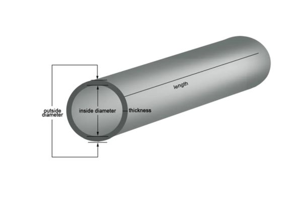
It’s important to note that this formula calculates the required internal diameter, not the hose’s nominal size or outside diameter. Hose catalogs typically list internal diameters, which should be used for comparison with calculated values.
B. Recommended Flow Velocities
Industry experience has established recommended flow velocity ranges for different parts of hydraulic systems:
Suction Lines (Pump Inlet): 0.6-1.2 m/s (2-4 ft/s)
- Lower velocities prevent cavitation
- Critical for system reliability
- Often the largest diameter hoses in the system
- Undersizing causes pump damage and reduced life
Pressure Lines: 3-6 m/s (10-20 ft/s)
- Main work circuits carrying pressurized fluid
- Higher pressures allow higher velocities
- Mobile equipment often uses higher end of range
- Industrial equipment typically uses lower end of range
Return Lines: 1.5-3 m/s (5-10 ft/s)
- Carrying fluid back to reservoir
- Lower pressure but still important for system efficiency
- Often overlooked in system design
- Undersizing causes backpressure on actuators
Specific Application Recommendations:
| Application Type | Suction Line | Pressure Line | Return Line |
| Industrial – Continuous | 0.6-0.9 m/s | 3-4 m/s | 1.5-2 m/s |
| Industrial – Intermittent | 0.9-1.2 m/s | 4-5 m/s | 2-2.5 m/s |
| Mobile Equipment | 0.9-1.2 m/s | 4.5-6 m/s | 2.5-3 m/s |
| High Performance | 1.2-1.5 m/s | 5-6 m/s | 2.5-3 m/s |
Data for information purposes only
Factors Justifying Deviations:
- Very short hose lengths may permit higher velocities
- Systems with minimal operating hours might accept higher velocities
- Critical applications may require more conservative (lower) velocities
- Extremely high pressure systems (>5000 PSI) often use lower velocities
Consequences of Exceeding Recommendations:
- Exponential increase in pressure drop
- Accelerated fluid degradation
- Increased noise and vibration
- Reduced component life
- System instability and poor response
C. Step-by-Step Calculation Process
Following a systematic process ensures appropriate hose diameter selection:
1. Determine Required Flow Volume:
- For cylinders: Q = (π × Bore² × Stroke) ÷ (4 × Extension Time)
- For motors: Q = (Displacement × RPM) ÷ 231 (for GPM)
- For multiple functions: Sum the flows that operate simultaneously
- Add a safety factor (typically 10%) for system variations
2. Select Appropriate Flow Velocity:
- Identify the circuit type (suction, pressure, return)
- Consider the application category from the recommendations table
- Adjust based on any special requirements or constraints
- Document the selected velocity for future reference
3. Calculate Theoretical Diameter:
- Apply the formula: d = √(0.3208 × GPM / v)
- Ensure consistent units throughout the calculation
- Calculate to at least three decimal places for accuracy
4. Adjust to Nearest Standard Size:
- Standard hydraulic hose sizes: 1/4″, 3/8″, 1/2″, 5/8″, 3/4″, 1″, 1-1/4″, 1-1/2″, 2″
- Always round up to the next larger size, never down
- Consider using the next size up if close to the threshold
- Verify pressure rating of selected hose size meets system requirements
5. Verification Calculations:
- Calculate the actual velocity with the selected hose: v = (0.3208 × GPM) ÷ d²
- Estimate pressure drop using manufacturer’s data or hydraulic calculators
- Verify the pressure drop is acceptable (typically <3% of system pressure)
- Document final selections and calculations for future reference
Example Calculation:
For a system requiring 20 GPM flow in a pressure line for mobile equipment:
- Flow: 20 GPM
- Recommended velocity: 5 m/s (16.4 ft/s)
- Theoretical diameter: d = √(0.3208 × 20 / 16.4) = 0.626 inches
- Standard size selection: 5/8″ (0.625″) or 3/4″ (0.75″)
- Verification with 5/8″ hose: v = (0.3208 × 20) ÷ (0.625)² = 16.4 ft/s (acceptable)
- Verification with 3/4″ hose: v = (0.3208 × 20) ÷ (0.75)² = 11.4 ft/s (more conservative)
The final choice between 5/8″ and 3/4″ would depend on system pressure, duty cycle, and other factors discussed previously.
Common Pitfalls and Optimization Strategies
A. Undersized Hose Problems
Undersized hydraulic hoses are among the most common and problematic issues in hydraulic systems:
Excessive Pressure Loss Symptoms:
- Slow actuator movement despite adequate pump flow
- Significant pressure difference between pump outlet and actuator
- Pressure gauges showing drops across hose runs
- System unable to reach maximum pressure under load
- Performance degradation as oil temperature increases
A properly sized system should have minimal pressure difference between the pump and actuators under normal operation.
Overheating Issues:
- Oil temperature rising above 140°F (60°C)
- Hot spots on hoses, particularly at bends
- Discoloration of hydraulic fluid
- Burnt odor from reservoir
- Frequent tripping of thermal protection devices
Remember that each 100 PSI of pressure drop converts to approximately 1°F temperature increase in the fluid.
Reduced Component Life:
- Premature pump failure due to cavitation (suction lines)
- Accelerated seal wear from excessive heat
- Valve spool erosion from high-velocity flow
- Filter bypass due to excessive pressure drop
- Hose failure, particularly at end fittings and bends
Component life can be reduced by 50% or more when operating at elevated temperatures caused by undersized hoses.
System Inefficiency and Performance Degradation:
- Increased energy consumption
- Reduced maximum force/torque output
- Inconsistent performance as temperature varies
- Inability to perform multiple functions simultaneously
- Longer cycle times than design specifications
Noise and Vibration Concerns:
- Excessive fluid noise, particularly at directional changes
- Pump cavitation noise (suction restrictions)
- Vibration in hoses and components
- Pressure pulsations and system instability
- Resonance issues in certain operating conditions
B. Oversized Hose Considerations
While less common than undersizing, oversized hoses present their own challenges:
Unnecessary Cost Implications:
- Higher initial purchase cost for hoses and fittings
- Increased fluid volume requirements
- More expensive manifolds and connection points
- Potentially more complex installation labor
- Larger support structures and clamps required
Space and Weight Penalties:
- Reduced clearance in tight installations
- Difficulty meeting minimum bend radius requirements
- Additional weight affecting equipment performance
- Larger fluid volume adding to overall weight
- More complex routing to accommodate larger diameters
Potential for Slower System Response:
- Increased fluid volume between valve and actuator
- More fluid compressibility affecting precision
- Potential for pressure wave issues in long lines
- Slower pressure buildup in certain applications
- Reduced natural frequency of hydraulic circuits
Installation Challenges:
- Difficulty routing through existing spaces
- Heavier assemblies requiring more support
- Larger minimum bend radius limiting routing options
- More difficult to connect to smaller components
- May require adapter fittings, creating additional leak points
When Oversizing Might Be Beneficial:
- Systems with anticipated future flow increases
- Applications where heat reduction is critical
- Very long hose runs where pressure drop accumulates
- Systems where noise and vibration must be minimized
- High-reliability applications justifying conservative design
C. Optimization Approaches
Strategic approaches can help optimize hydraulic hose diameter selection:
Critical Path Analysis for Prioritizing Diameter Upgrades:
- Identify the most flow-restrictive paths in the system
- Calculate pressure drops in each section
- Prioritize upgrades to sections with highest pressure drops
- Focus on suction lines first, then pressure lines, then return lines
- Address short, high-flow sections before longer, lower-flow sections
Balanced System Design Principles:
- Match hose diameters to connected component port sizes where possible
- Maintain consistent or gradually changing diameters throughout flow paths
- Consider the entire system rather than individual components
- Balance theoretical optimization against practical constraints
- Document design decisions for future reference
Using Different Diameters in Different Circuit Sections:
- Size suction lines larger than pressure lines
- Consider larger diameters for long runs
- Use smaller diameters for short connections between closely-spaced components
- Adapt diameter to flow requirements in different branches
- Transition gradually between different diameters when possible
Hybrid Approaches for Complex Systems:
- Combine rigid tubing and flexible hoses strategically
- Use manifolds to minimize connection points
- Consider parallel hoses for very high flow requirements
- Implement accumulators to manage peak flows
- Use specialized low-pressure-drop fittings at critical junctions
Maintenance and Inspection Considerations
A. Monitoring for Diameter-Related Issues
Regular monitoring helps identify when hose diameter issues are affecting system performance:
Pressure Drop Testing Procedures:
- Install pressure gauges at both ends of suspected hose runs
- Operate system at normal flow rates and record pressure differences
- Calculate pressure drop as a percentage of system pressure
- Compare to baseline measurements and acceptable limits
- Prioritize replacement of hoses with excessive pressure drop
Acceptable pressure drop limits:
- Suction lines: <0.3 bar (5 PSI)
- Pressure lines: <3% of system pressure
- Return lines: <1 bar (15 PSI)
Temperature Monitoring Techniques:
- Measure fluid temperature at reservoir during normal operation
- Use infrared thermometer to check hose surface temperatures
- Look for “hot spots” indicating flow restrictions
- Monitor temperature rise over operating cycle
- Compare to ambient temperature and acceptable limits
Warning signs:
- Oil temperature above 65°C (150°F)
- Localized hose temperatures 10°C higher than general system
- Rapid temperature rises during operation
- Temperature differential across components
Flow Testing Methods:
- Use portable flowmeters to verify actual flow rates
- Compare to expected values based on pump displacement
- Check flow at various points in the system
- Measure flow under different load conditions
- Verify flow balance in parallel circuits
Indicators of diameter issues:
- Flow decreasing as temperature increases
- Significant flow differences before and after hose runs
- Inability to achieve specified flow at normal pressure
- Flow fluctuations during steady operation
Visual Inspection Guidelines:
- Check for hose deformation, particularly at bends
- Look for discoloration indicating overheating
- Inspect for bulging under pressure
- Examine fittings for leakage or weeping
- Verify proper routing and absence of kinking
Document all findings in a maintenance log to track changes over time and identify developing issues before they cause system failure.
B. When to Reconsider Diameter Selection
Several triggers should prompt reevaluation of hydraulic hose diameters:
System Modification Triggers:
- Pump replacement with different flow capacity
- Addition of new actuators or functions
- Changes in operating pressure
- Cycle time reduction requirements
- Conversion to different hydraulic fluid
Any significant change to system requirements should include verification that existing hose diameters remain appropriate.
Performance Degradation Indicators:
- Increasing cycle times
- Rising operating temperatures
- Difficulty achieving maximum pressure
- Erratic operation or instability
- Increased noise or vibration
These symptoms often indicate that the system has “outgrown” its original hose sizing, particularly if they develop gradually over time.
Efficiency Improvement Opportunities:
- Energy audit identifying hydraulic system losses
- Cost reduction initiatives
- Sustainability and carbon footprint projects
- Competitive pressures requiring improved performance
- Utility rate increases making efficiency more valuable
Even properly functioning systems may benefit from diameter optimization as part of broader efficiency improvements.
Technological Advancement Considerations:
- Availability of new hose constructions with lower pressure drop
- Advanced fittings with improved flow characteristics
- Modern design tools allowing more precise optimization
- Better understanding of system dynamics
- Improved measurement and monitoring capabilities
As hydraulic technology evolves, best practices for diameter selection also advance, potentially justifying updates to older systems.
Conclusion
By approaching hydraulic hose diameter selection as a critical engineering decision rather than an afterthought, designers and maintenance personnel can significantly improve system performance, efficiency, and reliability. The investment in proper sizing pays dividends throughout the system’s operational life in reduced energy consumption, lower maintenance costs, and improved productivity.
If you want to choose high quality hydraulic hoses, contact Topa. We will provide the best hydraulic products for you!
FAQ
Why is hose diameter important in hydraulic systems?
Hose diameter affects how much fluid can pass through. A wrong size can cause pressure loss or overheating.
How do I choose the right hose diameter?
Base your choice on the flow rate, fluid type, system pressure, and hose length. Use sizing charts for guidance.
What happens if the hose is too small?
A hose that’s too small can restrict flow, increase pressure drop, reduce system efficiency, and cause heat buildup.
What if the hose is too large?
Oversized hoses add cost, weight, and may cause slower system response without major performance benefits.
Is flow rate the same as fluid velocity?
No. Flow rate is volume over time (e.g., GPM or L/min), while velocity is the speed of the fluid inside the hose.
Are there tools to help select hose diameter?
Yes, many manufacturers offer sizing calculators, apps, and charts to help choose the right diameter for your needs.