Confirm the connection, sealing features, hose-side geometry, body dimensions, and installation envelope before identifying or replacing a one-piece fitting. The essential one-piece hydraulic fitting dimensions include thread diameter and pitch, seat or sealing-face geometry, hose stem and ferrule details, overall length, and elbow offsets when applicable. A photo, swivel nut, connection name, or matching dash size can narrow the possibilities, but none proves compatibility. Missing one dimension can lead to a fitting that threads together yet does not seal, a hose-and-fitting combination without valid crimp data, or an assembly that collides with nearby components. The following checks turn an incomplete description into a controlled identification process.
Why Appearance Alone Cannot Confirm a Fitting
Appearance is useful for sorting candidates, but it cannot establish a final fitting model. Similar bodies and swivel nuts may conceal different threads, seats, seals, hose stems, ferrules, or series-specific assembly requirements.
Visible features show only part of the design
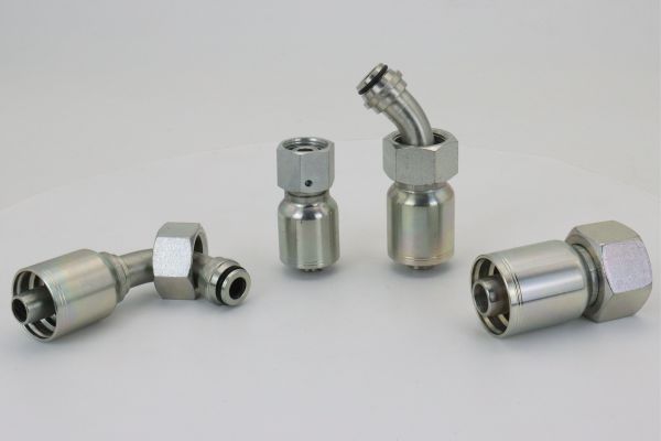
A clear photo can reveal whether a fitting is straight, angled, male, female, flanged, or fitted with an O-ring in a visible location. It can also show wrench flats, a swivel nut, an elbow, and obvious damage. However, perspective can distort diameter and length, while dirt, wear, plating, or a retained seal can hide the surface that actually makes the connection.
Terms such as “female swivel” describe movement and connection gender, not a complete standard. They do not establish the thread form, diameter, pitch or TPI, seat angle, sealing face, O-ring arrangement, hose size, fitting series, or elbow orientation. Even a legible old part number should be treated as a lead until it is checked against current technical information and the actual component.
Dash size is not a universal identity
A dash marking may refer to a nominal hose size or another catalog convention, depending on where it appears. It does not prove that the connection end and hose end use the same nominal size, nor does it confirm interchangeability between product series. Two fittings can share a dash designation while using different stem profiles, ferrules, thread connections, or crimp specifications.
The one-piece structure also does not remove the need for verification. In this type of fitting, the body or stem and ferrule are preassembled, attached, or retained together, but exact construction varies by series. Preassembly may reduce separate ferrule picking, yet it does not automatically confirm hose compatibility, correct crimping, pressure suitability, or sealing performance.
Connection-Side One-Piece Hydraulic Fitting Dimensions
Measure the connection end as a complete interface rather than recording only the apparent thread diameter. Reliable hydraulic fitting identification separates thread form, connection standard, diameter, pitch, taper, gender, seat, and seal.
Thread diameter, pitch, and taper
Measure a male thread across its outside diameter and a female thread at the accessible inside diameter using suitable tools and a consistent method. Then determine pitch with a thread-pitch gauge or TPI gauge, as appropriate. A diameter reading alone can leave several possible standards, especially when wear, coating, limited access, or measurement technique affects the result.
Determine whether the thread is straight or tapered instead of judging from a short visible section. Compare measurements along the thread when the applicable identification procedure calls for it, and inspect the thread form rather than forcing the fitting into a known port. Thread engagement is not proof of a match; partial engagement between incompatible forms can damage threads and still fail to create the intended seal.
Connection standard and reference dimensions
The connection standard defines how several features work together. Record only the thread length, nut, shoulder, pilot, flange, or sealing-surface references required by the applicable identification method and verified drawing.
| Measurement area | Record | Why it matters |
| Thread | Gender, measured diameter, pitch or TPI, straight or tapered form | Separates similar-looking connection candidates |
| Engagement features | Thread length, pilot, shoulder, or flange geometry when relevant | Helps compare the part with a verified drawing |
| Reference condition | Wear, damaged crests, coating, contamination, and measurement points | Explains why a reading may differ from nominal data |
| Source evidence | Existing marking, equipment port data, and clear close-up photos | Supports confirmation without relying on appearance alone |
Do not use thread sealant to compensate for a wrong standard, damaged threads, an incorrect seat, or a damaged sealing face. Sealant has a limited role only where the designed connection and current procedure call for it. It cannot convert one thread or sealing system into another.
Seat Angle, Sealing Face, and O-Ring Confirmation
The fitting must seal by the intended surface or seal element, not merely by holding threads together. Confirm the seat geometry, sealing-face condition, and O-ring position independently from the thread measurements.
Identify where sealing occurs
Inspect whether sealing is designed to occur on tapered threads, a flare seat, a cone, a flat face, an O-ring, a bonded seal, or another engineered surface. A female swivel can contain an internal seat that is difficult to see in a straight-on photograph, and different seat forms may sit behind similar nuts. Use an appropriate seat gauge, profile comparison, technical drawing, or verified mating-component data instead of estimating an angle by eye.
Record the seat diameter or other drawing reference dimensions when they are required to distinguish candidates, but do not publish or assume a nominal value without a verified source. Check the face for scoring, deformation, corrosion, embedded debris, or previous over-tightening. A correct standard with a damaged sealing surface may still leak, so identification and condition assessment are separate decisions.
Locate and assess the seal
For an O-ring connection, record whether the seal sits on the male end, in a face groove, around a boss, behind a flange, or elsewhere in the designed interface. Note groove condition and the presence of a backup element when relevant, but do not select a replacement seal from appearance alone. Material, dimensions, fluid, temperature, and the applicable component data all affect seal suitability.
A missing O-ring can make a fitting appear to use a metal-to-metal seal, while a loose O-ring may have been added incorrectly. Preserve removed components for examination, but verify the intended arrangement against current documentation. Never pressurize an uncertain connection simply to see where it leaks, and never check a suspected high-pressure leak with a hand.
Hose-Side Stem, Ferrule, and Fitting-Series Checks
The connection end can be correct while the hose end is wrong. A safe replacement requires a documented combination of hose manufacturer or compatible specification, hose series, hose ID, reinforcement, fitting series, ferrule design, and current crimp data.
Measure without treating the stem as universal
Record the hose size indicated by reliable markings and confirm the actual hose ID and construction from current product information. For an unassembled or approved inspection sample, relevant stem features may include insertion length, nipple profile, sealing or retention features, and the position of a hose stop. Ferrule references may include length, outside geometry, retention method, and its relationship to the stem, but measurement must not become an improvised crimp specification.
Do not disassemble a retained one-piece fitting merely to obtain hidden dimensions unless the applicable procedure allows it and the part is being removed from service. Cutting or separating the ferrule can destroy evidence and create sharp or spring-loaded material. When internal geometry cannot be measured safely, use the series marking, verified drawing, or manufacturer data to complete the identification.
Confirm the complete assembly system
The same hose dash size does not guarantee that two stems or ferrules are compatible. Hose cover thickness, reinforcement construction, tube dimensions, fitting-tail design, ferrule compression, and series tolerances can differ. A fitting that slides into a hose is not thereby approved for crimping.
Before assembly, require current data for:
- the exact hose manufacturer or accepted specification, hose series, construction, ID, and dash size;
- the fitting body or stem, ferrule, and complete fitting-series identification;
- hose preparation, including skive or no-skive requirements when applicable;
- the crimping machine, die set, crimp diameter, insertion method, and inspection criteria; and
- cleaning, proof or pressure testing when required by the applicable procedure.
Never create a crimp value from an old assembly’s approximate outside measurement. The old part may be worn, incorrectly assembled, or made to different data, and an external reading does not reveal internal compression. Follow the current hose, fitting, and crimp-equipment instructions for the exact combination.
Overall Length, Elbow Geometry, and Installation Clearance
Overall geometry determines whether an identified fitting can actually be installed and routed. Measure from defined reference points and record the fitting orientation, because loose end-to-end measurements can change with swivel position or an unclear datum.
Use consistent body and elbow references
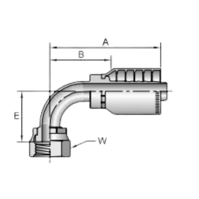
For a straight fitting, record overall length and the location of shoulders, wrench flats, stops, or other drawing references needed for comparison. For a 45-degree or 90-degree fitting, record the relevant centerline offsets, drop length, and connection orientation using the same datums as the technical drawing. Do not compare one supplier’s overall dimension with another drawing’s centerline dimension as though they were equivalent.
Swivel position can also affect a casual measurement. Seat the nut only as the approved measurement procedure requires, without forcing it, and state whether the measurement is taken to a seat, thread end, face, centerline, or body shoulder. Photos should include a scale only as supporting evidence; calibrated tools and written dimensions are needed for final confirmation.
Check the machine envelope
A geometrically different replacement may fit the hose and port yet collide with a guard, cylinder, frame, or adjacent line. Verify wrench access, assembly installation path, bend allowance after the fitting, clamp positions, and clearance throughout machine movement. Elbow clocking is especially important when both ends have fixed orientations or when a swivel cannot rotate after tightening.
Before removal or measurement, stop the equipment, isolate the hydraulic system, release hydraulic pressure and stored energy, secure raised or suspended loads, and follow applicable lockout procedures. Follow the equipment manufacturer’s instructions and use appropriate personal protective equipment. Never loosen a connection to confirm its type while the circuit may still be pressurized.
Step-by-Step Fitting Measurement Process
Use a repeatable sequence that preserves evidence and separates observation from confirmation. This reduces the chance that an early guess about the connection controls every later measurement.
Measure from system context to component detail
- Make the equipment safe. Isolate and depressurize the circuit, control stored energy, secure loads, clean the area, and confirm that removal is permitted.
- Record the installed assembly. Photograph the complete route, both end connections, elbow orientation, clamps, clearances, hose markings, and any readable part identification.
- Identify the hose. Record manufacturer or specification, series, construction, hose ID, dash size, and condition without assuming the fitting dash is identical.
- Measure the connection. Record gender, thread diameter, pitch or TPI, straight or tapered form, thread length, and applicable shoulder, pilot, or flange references.
- Confirm the seal. Identify the seat or sealing face, measure only the references required by verified data, locate O-rings, and document surface damage.
- Record body geometry. Measure overall length, wrench flats, offsets, drop length, elbow angle and clocking, using clearly stated datums.
- Verify the assembly series. Match the hose, fitting, ferrule, preparation, crimper, die, crimp specification, and inspection method in current applicable data.
Avoid common measurement and ordering errors
Common mistakes include rounding a measured thread to the nearest familiar size, confusing pitch with TPI, measuring across damaged crests, and describing the connection only as “female swivel.” Other errors include copying the hose dash size to both ends, omitting the sealing face, measuring elbow length from inconsistent points, or assuming a photo confirms scale.
Do not order solely from the old part number, especially when the source, revision, or series is uncertain. Do not force a candidate fitting into a port as a thread test, reuse visibly damaged components, or accept an approximate crimp as validation. When measurements conflict with catalog data, recheck the tools, datums, wear, and candidate standard before choosing a replacement.
Information Checklist to Prepare Next
A complete identification package should let another qualified person repeat the comparison without relying on your original guess. Keep the old component available when safe, label every measurement, and distinguish observed facts from unverified assumptions.
Connection and geometry record
Prepare the following neutral information:
- full fitting photos plus close-ups of the thread, seat, sealing face, O-ring location, body marking, stem, and ferrule;
- male or female connection, measured thread diameter, pitch or TPI, and straight or tapered form;
- sealing method, seat or face condition, required reference dimensions, and mating-port information;
- straight, 45-degree, or 90-degree form, overall length, reference datums, drop or offset dimensions, and elbow orientation; and
- equipment clearance, wrench access, route, movement, vibration, temperature, fluid, and verified pressure requirement.
Hose and assembly record
Add the hose manufacturer or accepted specification, hose series, construction, ID, dash size, reinforcement, and readable markings. Record the fitting and ferrule series, crimping machine, die set, current crimp specification, preparation method, inspection requirements, and the intended application. Unknown fields should remain marked as unknown until verified rather than being filled with a likely value.
Conclusion
The complete assembly is limited by its lowest-rated component and must follow current manufacturer procedures. Preparing labeled measurements, clear photos, hose data, application conditions, and assembly information makes the next one-piece hydraulic fitting dimensions decision traceable and safer.
Looking for a reliable one-piece hydraulic fitting supplier or a compatible replacement for an existing model? Contact Topa today to submit your one-piece fitting requirements and receive a detailed technical review and quotation.
FAQ
Can a fitting be identified from its thread diameter alone?
No, thread diameter alone cannot confirm the connection. Pitch or TPI, thread form, taper, gender, seat, and sealing method must also match verified technical data.
Does a female swivel nut identify the sealing standard?
No, a female swivel nut describes only part of the connection. Similar nuts can contain different internal seats, threads, sealing faces, or O-ring arrangements.
Can two one-piece fittings with the same dash size be interchanged?
No, matching dash sizes do not prove interchangeability. Confirm the hose construction, fitting and ferrule series, connection, geometry, and current crimp specification for each product.
Should the old crimp diameter be copied for a replacement fitting?
No, an old external measurement is not a valid replacement crimp specification. Use current data for the exact hose, fitting, ferrule, crimper, and die combination.
What should be done when measurements do not match a catalog drawing?
Recheck the measurement points, tools, thread condition, datums, and assumed connection standard before ordering. If the conflict remains, obtain verified technical confirmation rather than selecting the closest-looking fitting.