
How to Install An Fitting on Braided Line
How to Install An Fitting on Braided Line Contact Us
How to Install An Fitting on Braided Line Contact Us

AN Fitting Types: What You Need to Know Contact Us

AN Fitting Repair: Step-by-Step Troubleshooting Table of Contents Introduction AN

How to Install AN Fittings to Hard Line? Contact Us

Why Is Your AN Fitting Leaking? Top Reasons and Fixes

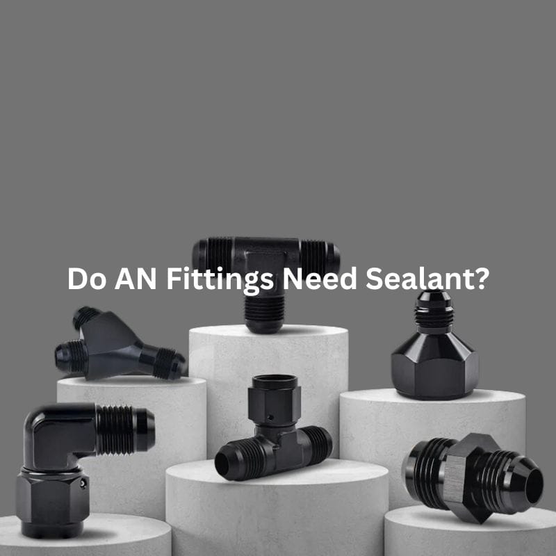
Do AN Fittings Need Sealant? Contact Us Introduction AN fittings
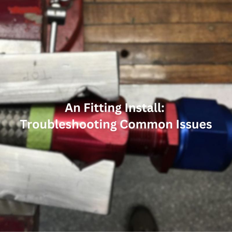
An Fitting Install: Troubleshooting Common Issues Contact Us Table of
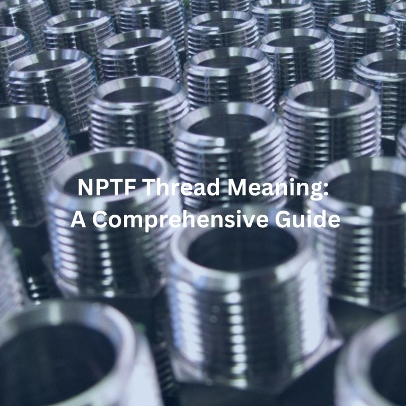
NPTF Thread Meaning: A Comprehensive Guide Contact Us Introduction Among

NPSM Thread Meaning: Unraveling the Basics Contact Us Table of