
Quick Connect Sizes Explained: A Comprehensive Comparison
Quick Connect Sizes Explained: A Comprehensive Comparison Introduction Quick-connect fittings
Quick Connect Sizes Explained: A Comprehensive Comparison Introduction Quick-connect fittings
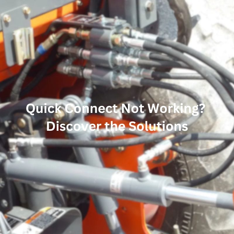
Quick Connect Not Working? Discover the Solutions Contact Us Table
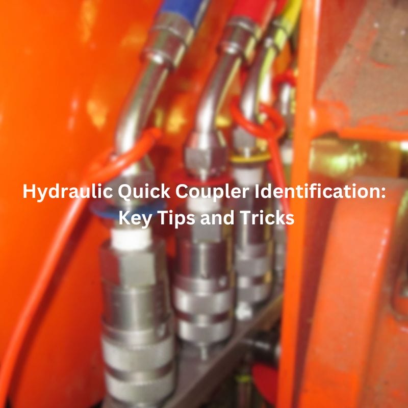
Hydraulic Quick Coupler Identification: Key Tips and Tricks Contact Us
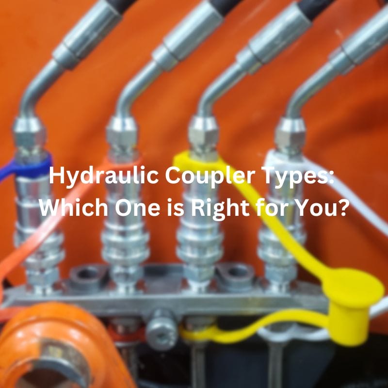
Hydraulic Coupler Types: Which One is Right for You? Contact
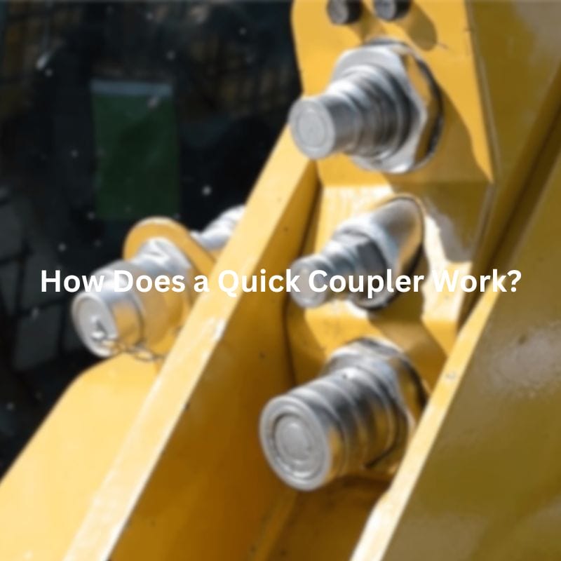
Stuck Hydraulic Quick Coupler? Here’s What to Do Next! Table

Compression vs Threaded Fitting: Choosing the Right Fitting Contact Us

Compression Fitting Failure: Warning Signs You Should Know Contact Us

Brake Line Union vs Compression Fitting: Which to Choose? Table

How Tight Should Compression Fittings Be Introduction Compression fittings play