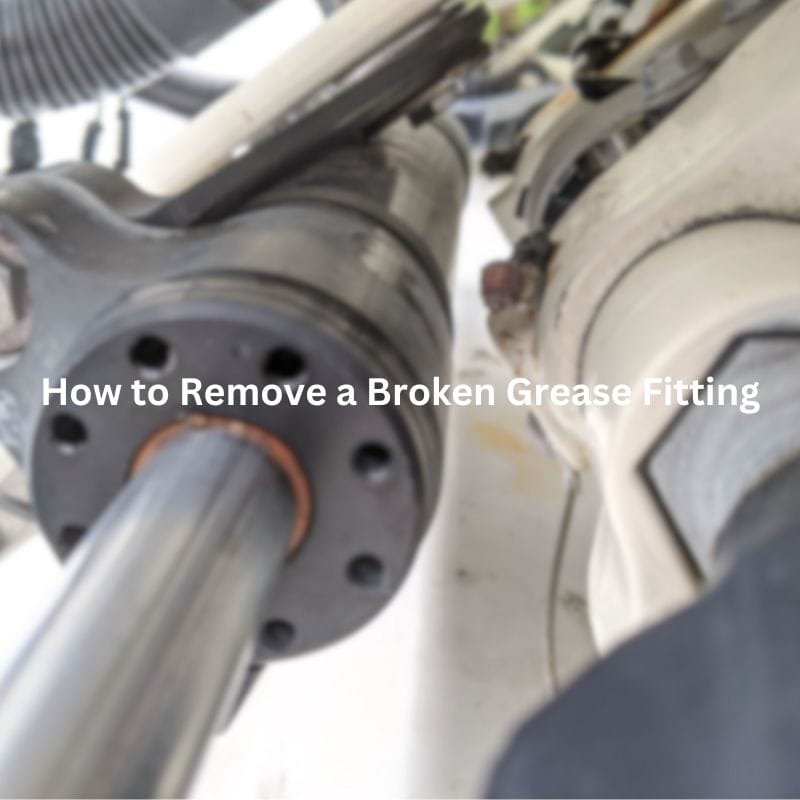
How to Remove a Broken Grease Fitting
How to Remove a Broken Grease Fitting Contact Us Table
How to Remove a Broken Grease Fitting Contact Us Table
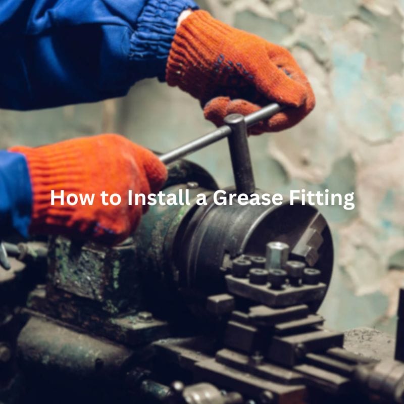
How to Install a Grease Fitting? Contact Us Introduction Grease

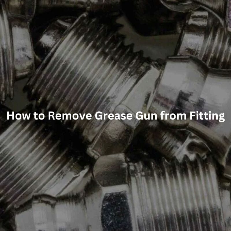
How to Remove Grease Gun from Fitting Contact Us Introduction
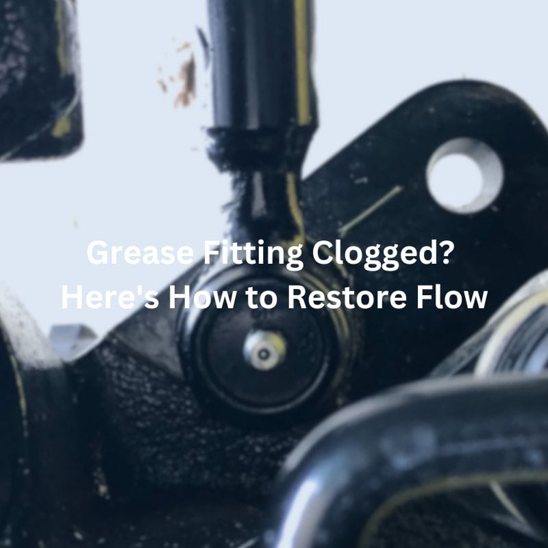
Grease Fitting Clogged? Here’s How to Restore Flow Contact Us

Hydraulic Quick Coupler Won’t Connect? Here’s What to Do Contact

How to Install Quick Coupler on Excavator Contact Us Introduction

How to Identify Hydraulic Quick Coupler? Contact Us Introduction Have

Quick Disconnect Fittings Definition: What You Need to Know Table

Flat Face Hydraulic Coupler Leaking? Fix It with These Steps