How to Install Barbed Hose Fittings

How to Install Barbed Hose Fittings

How to Install Barbed Hose Fittings?

Table of Contents

Introduction

Barbed hose fittings are specialized connectors designed to create a secure, leak-resistant joint between a hose and another component, typically a pipe or another hose. These fittings feature barbs or ridges along their outer surface that grip the inside of the hose when inserted, providing a tight seal.

Definition and Components of Barbed Hose Fittings

Barbed Hose Fittings Components

Barbs: These are the ridges or serrations along the fitting’s surface that grip the hose when inserted, ensuring a tight seal.

Body: The main body of the fitting, which varies in shape and size depending on its specific application and connection requirements.

Threads: Some fittings may include threaded ends to facilitate attachment to other components such as pipes or equipment.

Types of Materials Used

Barbed hose fittings are available in a variety of materials to suit different applications and environmental conditions:

Brass: Commonly used for its durability, corrosion resistance, and suitability for hot water and hydraulic applications.

Stainless Steel: Known for its strength, corrosion resistance, and ability to withstand high temperatures and pressure.

Plastic (e.g., Nylon, Polypropylene): Lightweight options suitable for less demanding applications where chemical resistance and cost-effectiveness are key considerations.

Applications in Different Industries

Barbed hose fittings find extensive use across various industries, including:

Automotive: Used for fuel lines, coolant systems, and vacuum hoses.

Plumbing: Ideal for connecting hoses to fixtures, water pumps, and irrigation systems.

Industrial: Essential for fluid transfer in manufacturing processes, pneumatic systems, and hydraulic machinery.

These fittings provide versatile and reliable connections that cater to specific operational requirements, ensuring efficient fluid handling and minimizing the risk of leaks in critical applications. Understanding the different types and materials of barbed hose fittings is crucial for selecting the right components that best fit your industry’s needs.

Choosing the Right Barbed Hose Fitting

The appropriate barbed hose fitting is crucial for establishing a reliable and efficient fluid handling system. Here are comprehensive factors to consider:

Material Compatibility

Chemical Compatibility: Ensure the fitting material is compatible with the fluids or gases it will encounter. This prevents chemical reactions that could lead to corrosion or material degradation over time.

Temperature and Pressure Ratings: Select fittings rated to withstand your specific application’s operating temperatures and pressures. This ensures safety and prevents performance issues under varying conditions.

Application Specificity

Industry Requirements: Adhere to industry standards and regulations that may specify certain materials or configurations for fittings. Compliance ensures compatibility with industry norms and enhances system reliability.

Environmental Conditions: Evaluate environmental factors such as UV exposure, abrasion, and weather conditions. Choose fittings that are resilient to these elements to maintain longevity and performance.

barb fitting

Size and Measurement Guidelines

Inner Diameter (ID): Accurately measure the inner diameter of the hose to select a fitting with an appropriate barb size. This step is critical for establishing a secure connection that maintains fluid integrity.

Thread Size: Determine the thread size needed for the fitting to properly attach to other components or equipment in your system. Matching thread types and sizes ensures compatibility and prevents potential leaks or fitting misalignment.

By carefully evaluating these factors and guidelines, you can confidently choose barbed hose fittings that meet your specific application requirements. This proactive approach enhances system reliability, minimizes downtime, and optimizes overall operational efficiency in industrial environments. Regular maintenance and periodic inspections further ensure continued performance and longevity of your fluid handling systems.

Common Mistakes to Avoid in Fitting Selection

Incorrect Material Selection: Choosing fittings that are not compatible with the fluid or environment can lead to premature failure or safety hazards.

Improper Sizing: Using fittings with mismatched sizes can cause leaks or fittings that are difficult to install.

Neglecting Pressure Ratings: Fittings rated below the operating pressure may fail under stress, causing leaks or system damage.

Ignoring Environmental Factors: Failing to consider environmental conditions can lead to fittings deteriorating prematurely due to exposure to chemicals, temperature extremes, or UV radiation.

Step-by-Step Installation Process

Ensure a successful installation of barbed hose fittings by following these detailed steps:

Preparation

Before beginning the installation process, it’s crucial to prepare adequately:

Inspecting the Hose and Fitting: Thoroughly examine both the hose and the barbed fitting for any signs of damage, such as cracks, cuts, or deformities. This step ensures that all components are in optimal condition to prevent leaks or failures during operation.

Cutting the Hose to the Correct Length: Measure and cut the hose to the appropriate length using hose cutters or a sharp utility knife. A clean, straight cut is essential to facilitate a proper seal with the barbed fitting, ensuring a secure connection.

Install Hose Barb

Lubrication

Proper lubrication enhances the installation process and ensures a secure connection:

Importance of Lubricating the Hose: Applying a suitable lubricant to the outside of the hose and the barbs of the fitting reduces friction during insertion. This minimizes the risk of damaging the hose material and makes it easier to achieve a tight fit without excessive force.

Types of Lubricants Suitable for Various Materials: Choose lubricants that are compatible with the hose material to avoid degradation or damage. For example, silicone lubricants are suitable for rubber hoses, while soapy water works well with plastic hoses. Avoid using petroleum-based lubricants, as they can deteriorate certain materials over time.

Insertion

Inserting the barbed fitting into the hose requires careful technique to ensure a secure and leak-free connection:

Techniques for Insertion: Gently twist and push the barbed fitting into the hose, employing a twisting motion to help the barbs grip the hose material securely. This technique ensures that the fitting is properly seated without damaging or distorting the hose.

Ensuring a Secure Fit Without Damaging the Hose: Avoid applying excessive force that could potentially damage the hose or stretch the material around the barbs. The fitting should fit snugly without gaps between the hose and the fitting body to maintain integrity.

Securing the Connection

Once the fitting is inserted, secure the connection effectively to prevent leaks:

Using Hose Clamps Effectively: Position hose clamps over the barbed portion of the fitting, ensuring they are evenly spaced and securely fastened around the hose. Select clamps that match the hose diameter to achieve optimal sealing and prevent movement.

Tightening the Clamp to Prevent Leaks: Gradually tighten the hose clamp using a screwdriver or wrench until it is snug against the hose and fitting. Be cautious not to over-tighten, as this may cause damage to the hose or fitting threads.

Testing the Installation

After securing the connection, it’s crucial to verify its integrity and functionality:

Methods for Pressure Testing the Connection: Utilize a pressure testing tool or apply compressed air or water to the system to check for leaks under operational conditions. Monitor the connection closely for any signs of leakage, especially around the barbed fitting and hose clamp areas.

Inspecting for Leaks and Addressing Any Issues: Thoroughly inspect all connections for leaks immediately after testing. If leaks are detected, revisit the installation steps to identify potential causes such as improper insertion, inadequate lubrication, or insufficient tightening of hose clamps. Make necessary adjustments to achieve a tight seal and ensure reliable performance.

By following these step-by-step guidelines, you can ensure the successful installation of barbed hose fittings, maintaining efficiency and reliability in your industrial applications. Regular inspections and proactive maintenance will further enhance system performance and longevity.

Troubleshooting Common Issues

Encountering challenges during the installation of barbed hose fittings is common in industrial applications. Here’s how to troubleshoot and resolve common problems effectively:

Identifying and Fixing Leaks

Inspect the Connection:

Check for Visible Signs of Leakage: Thoroughly examine the area around the fitting and hose clamp for any signs of moisture or drips.

Trace the Leak: Identify the source of the leak, which may result from improper insertion, insufficient tightening of the hose clamp, or compatibility issues between materials.

Reevaluate Installation Steps:

Ensure Proper Insertion: Verify that the barbed fitting is correctly inserted into the hose without causing damage to the hose material or fittings.

Secure Hose Clamp: Ensure the hose clamp is securely tightened around the barbed fitting, creating a tight seal without gaps.

Apply Sealant or Tape:

Use Thread Sealant or Teflon Tape: Apply a suitable thread sealant or Teflon tape to threaded fittings to prevent leaks at connection points.

Seal Around Hose Barb: Apply a small amount of sealant around the hose barb before inserting it into the hose to enhance sealing and prevent leaks.

Replace Damaged Components:

Inspect and Replace: If leaks persist despite adjustments, inspect and replace damaged hoses, fittings, or clamps that may be causing the issue to ensure a secure connection.

Push Lock Fittings with Clamps

Addressing Fittings That Are Difficult to Install

Lubricate Adequately:

Use Suitable Lubricant: Apply a lubricant compatible with the hose and fitting materials to reduce friction during installation and ease fitting insertion.

Ensure Compatibility: Verify that the lubricant chosen does not degrade or damage the materials involved.

Use Proper Tools and Techniques:

Utilize Hose Cutters: Use hose cutters to achieve clean, straight cuts on the hose, facilitating easier installation of fittings.

Techniques for Insertion: Employ twisting and pushing motions when inserting the fitting into the hose to help the barbs grip securely without applying excessive force.

Consider Heat Assistance:

Heat Application: For rigid or stubborn hoses, gently heat the hose with hot water or a heat gun to increase flexibility, making it easier to fit onto the barbed fitting without damaging the materials.

Handling Compatibility Issues Between Hose and Fitting Materials

Verify Material Compatibility:

Check Manufacturer Specifications: Refer to manufacturer guidelines or consult with suppliers to confirm compatibility between the hose and fitting materials to avoid chemical reactions, corrosion, or degradation.

Select Appropriate Fittings:

Material Selection: Choose fittings made from materials that are compatible with the fluid or gas being transferred through the system to ensure long-term reliability and performance.

Consider Environmental Factors: Evaluate environmental conditions such as UV exposure, temperature variations, and chemical exposure that may affect material integrity.

Implement Protective Measures:

Use Specialized Materials: Consider using fittings with alternative materials or coatings that enhance compatibility and durability in challenging environments.

Protective Coatings: Apply protective coatings or treatments to fittings exposed to harsh conditions to prolong their lifespan and maintain performance.

By following these troubleshooting steps and proactive measures, you can effectively resolve installation challenges with barbed hose fittings, ensuring reliable operation and minimizing potential issues in industrial settings. Regular inspection and maintenance will further enhance system integrity and performance over time.

Maintenance and Best Practices

Maintaining barbed hose fittings is essential for prolonging their lifespan and ensuring reliable performance in industrial applications. Here are key tips and best practices:

Tips for Maintaining Barbed Hose Fittings

Broken hydraulic fitting Topa

Regular Inspection:

Conduct routine inspections of fittings, hoses, and clamps for signs of wear, corrosion, or leaks.

Inspect fittings after installation and periodically during operation to detect potential issues early.

Replacement Schedules:

Establish a maintenance schedule for replacing fittings and hoses based on manufacturer recommendations or observed wear.

Replace components promptly if they show signs of damage or deterioration to prevent failures and leaks.

Cleaning and Lubrication:

Clean fittings and hoses regularly to remove debris, dirt, or contaminants that can affect sealing and performance.

Apply appropriate lubrication during installation and maintenance to facilitate easier fitting insertion and prevent friction-related damage.

Tightening and Adjustment:

Ensure hose clamps are securely tightened to maintain a tight seal around barbed fittings.

Periodically check and adjust clamp tightness to compensate for any loosening due to vibration or temperature changes.

Best Practices for Ensuring Longevity and Performance

Use Compatible Materials: Select fittings and hoses that are compatible with the fluids, gases, and environmental conditions they will encounter.

Follow Installation Guidelines: Adhere to manufacturer installation instructions and industry best practices to ensure proper fitting assembly and sealing.

Monitor Operating Conditions: Regularly monitor operating temperatures, pressures, and environmental factors to anticipate potential issues and take preventive action.

Conclusion

In summary, selecting and installing barbed hose fittings requires attention to detail and adherence to best practices to ensure optimal performance and longevity. By employing safe installation techniques and proactive maintenance, you can maximize the efficiency and longevity of barbed hose fittings to ensure the continued success of your industrial operations.

FAQ

BSP hydraulic hose fittings are standardized fittings used to connect hydraulic hoses and pipes. They ensure a secure and leak-free connection in hydraulic systems.

Topa provides a wide range of BSP hydraulic hose fittings in various sizes to accommodate different hydraulic system requirements. 

Yes, Topa’s BSP hydraulic hose fittings are designed to meet international standards and are compatible with fittings from other reputable brands. This ensures versatility and ease of integration into existing hydraulic setups.

Our BSP hydraulic hose fittings are manufactured using high-quality materials such as [specify materials, e.g., stainless steel, brass] to ensure durability, corrosion resistance, and long-term performance in demanding environments.

Yes, Topa understands the importance of meeting specific customer requirements. We offer customization options for BSP hydraulic hose fittings, including special sizes, configurations, and finishes to suit unique applications.

Ordering from Topa is straightforward. Simply [describe the ordering process, e.g., visit our website, contact our sales team], provide details about the BSP hydraulic hose fittings you need, and our team will assist you with pricing, availability, and delivery options.


More Posts

Explore Hydraulic Flange Types

Explore Hydraulic Flange Types: A Comprehensive Overview

Explore Hydraulic Flange Types: A Comprehensive Overview

Introduction

Hydraulic flange fittings allow for a secure and leak-free connection, which is essential for efficient fluid transfer. These fittings are key components in hydraulic systems that ensure seamless operation and reliability under varying pressures and environmental conditions. By securely connecting pipes, tubes, or hoses, hydraulic flange couplings prevent fluid leakage, thereby maintaining system integrity and optimizing performance. Their importance lies not only in functional reliability but also in their ability to improve operational safety and reduce maintenance costs.

What are Hydraulic Flange Fittings?

Hydraulic flange fittings are essential components characterized by a flat surface featuring grooves and an O-ring on one end. This design is meticulously crafted to establish a robust seal, crucial for containing fluids under high pressures within hydraulic systems. The opposite end of these fittings is adaptable, typically connecting to either a hose or threaded component, thereby enabling versatile applications across diverse industrial environments.

One pivotal aspect of hydraulic flange fittings is their integration with flange clamps. These clamps play a pivotal role in ensuring the fittings’ secure attachment to pipes or machinery, thereby enhancing system reliability. By facilitating easy assembly and disassembly, hydraulic flange fittings with flange clamps allow for efficient maintenance procedures, minimizing downtime and operational disruptions.

Types of Hydraulic Flange Fittings

Hydraulic systems rely on various types of flange fittings to ensure secure connections and efficient fluid transfer across different applications and industries. Here’s an overview of the key types:

Hydraulic Hose Flange Fitting

Hydraulic hose flange fittings are specialized components essential for securely connecting hoses to hydraulic systems, ensuring reliable fluid transfer and containment. These fittings are available in various pressure ratings tailored to different operational needs:

SAE Code 61/3000 psi: This type of hydraulic hose flange fitting is well-suited for medium-pressure hydraulic applications. It provides a secure connection that can withstand pressures up to 3000 pounds per square inch (psi), making it suitable for a wide range of industrial and mobile hydraulic equipment.

SAE Code 62/6000 psi: Designed for higher-pressure hydraulic systems, SAE Code 62 fittings offer robust performance under increased pressure levels. With a pressure rating of 6000 psi, these fittings are commonly used in demanding hydraulic applications where durability and reliability are crucial, such as heavy machinery and construction equipment.

High-pressure/9000 psi: For extreme high-pressure environments, hydraulic hose flange fittings rated at 9000 psi provide exceptional strength and sealing capabilities. These fittings are specifically engineered to handle intense hydraulic pressures found in specialized industrial applications, including mining operations, offshore drilling rigs, and high-performance hydraulic systems.

Each type of hydraulic hose flange fitting is meticulously designed to ensure compatibility with specific pressure requirements and operational conditions. By selecting the appropriate fitting based on pressure ratings and application needs, industries can achieve optimal performance, reliability, and safety in their hydraulic systems.

Hydraulic flange fittings China Manufacturer Topa in China

Thread Flange Fitting

Thread flange fittings are versatile components designed with threads on both the inside and outside, facilitating the connection of pipes or valves in hydraulic and fluid handling systems. This dual-threaded design offers significant advantages in terms of assembly, disassembly, and maintenance:

Versatile Connectivity: Thread flange fittings provide a flexible solution for joining pipes or valves without requiring welding. The threaded design allows for easy installation and removal, making them ideal for applications where frequent assembly and disassembly are necessary.

Sealing Capabilities: Properly tightened threaded flange fittings create a secure seal, preventing leaks and ensuring reliable fluid containment. This sealing capability is crucial for maintaining system integrity and operational safety in hydraulic applications.

Slip-On Flanges

Slip-on flanges are characterized by their simple yet effective design, which facilitates easy installation and alignment in various industrial applications. Here’s a detailed overview of their external features and typical uses:

External Appearance: Slip-on flanges feature a flat, circular shape with a raised face on the sealing surface. This raised face helps in creating a tight seal when the flange is welded to the pipe, ensuring leak-free operation. They also have a smooth inner bore that matches the pipe diameter, allowing for seamless flow of fluids through the system.

Usage and Applications: Slip-on flanges are commonly used in scenarios where ease of installation and cost efficiency are priorities. They are particularly favored in less critical applications or systems with moderate pressure requirements. Industries such as water treatment plants, low-pressure hydraulic systems, and plumbing installations often utilize slip-on flanges due to their straightforward installation process and lower initial cost compared to other flange types.

Limitations in High-Pressure Environments: While slip-on flanges offer advantages in terms of ease of installation, they may have limitations in high-pressure environments. The welding connection, while robust, may not provide the same level of strength and pressure resistance as weld neck or socket weld flanges. Therefore, slip-on flanges are typically recommended for applications where moderate pressures are anticipated and where the operational demands do not require the highest level of structural integrity.

SAE Socket Weld Flange flat factory

Socket Weld Flanges

Socket weld flanges have a socket-like end with an internal bore that matches the outer diameter of the pipe. This design allows the pipe to be inserted into the socket, creating a precise fit. The flange also features a flat, circular face with bolt holes for securing it to another flange or component using bolts and nuts. The sealing surface may be raised to accommodate a gasket for optimal sealing.

Usage and Applications: Socket weld flanges are primarily used in systems where moderate pressures and smaller pipe sizes are involved. They are particularly suitable for piping systems handling fluids such as water, steam, oil, and gas in industries such as petrochemical, chemical processing, and food processing. Their robust construction and secure weld connection make them ideal for applications requiring reliable sealing and fluid containment.

Connection Method: The installation of socket weld flanges involves inserting the pipe into the socket end and then performing fillet welding around the joint. This welding method creates a strong and permanent connection that enhances structural integrity and minimizes the risk of leaks. Socket weld flanges are preferred for their simplicity in installation and maintenance, allowing for easy inspection and disassembly when necessary.

Flow Dynamics: Due to their smooth internal bore and precise fit with the pipe, socket weld flanges promote excellent flow dynamics within the system. This feature reduces turbulence and pressure drop, contributing to efficient fluid transfer and operational efficiency.

Blind Flanges

Blind flanges are flat, solid plates with no openings or bores. They feature a raised face on the sealing surface, which accommodates a gasket for creating a tight seal when bolted to another flange or component. The bolt holes around the perimeter allow for secure attachment using bolts and nuts.

Functionality: The primary function of blind flanges is to block off or seal the end of a pipeline, valve, or pressure vessel opening. By preventing the flow of fluids or gases, blind flanges ensure system integrity and safety during maintenance, inspection, or when future expansion is anticipated. They are commonly used to isolate sections of pipelines or equipment that require temporary or permanent closure.

Applications: Blind flanges find widespread application in various industries, including oil and gas, chemical processing, pharmaceuticals, and water treatment plants. They are essential in hydraulic systems where fluid control, system isolation, or pressure containment is critical. Blind flanges are particularly useful during system shutdowns, maintenance procedures, or when performing hydrostatic testing to verify the integrity of pipelines or vessels.

Types and Variations: Blind flanges are available in different types to accommodate specific operational requirements. They may include standard blind flanges with raised faces for standard sealing applications or special blind flanges designed for high-pressure or corrosive environments. The selection of materials such as carbon steel, stainless steel, or alloy steel ensures compatibility with varying fluid types and system conditions.

Installation and Maintenance: Installing blind flanges involves aligning the flange with the pipe or equipment opening and bolting it securely in place. The use of a suitable gasket between the flange faces ensures a leak-proof seal. Maintenance of blind flanges typically involves periodic inspection, gasket replacement, and ensuring proper bolt torque to maintain sealing integrity.

Lap Joint Flanges

Lap joint flanges are unique components designed to facilitate easy assembly, alignment, and maintenance in hydraulic and industrial piping systems. Here’s a detailed exploration of their features and practical applications:

Component Design: Lap joint flanges consist of two main components:

Stub End: A short piece of pipe with a welded or flanged connection to the pipeline.

Backing Flange: A circular disc with bolt holes that slides over the pipe end and overlaps the stub end.

Assembly and Installation: The installation of lap joint flanges involves:

Welding the stub end to the pipe.

Sliding the backing flange over the pipe end until it rests against the stub end.

Securing the flange to the stub end using bolts and nuts through the bolt holes in the backing flange.

Sealing and Compatibility: Lap joint flanges utilize a gasket placed between the stub end and the backing flange to achieve a secure seal. This sealing method allows for easy replacement of the gasket when necessary, enhancing maintenance efficiency. Lap joint flanges are available in various materials and pressure ratings to suit different operational requirements, ensuring compatibility with diverse piping configurations and fluid handling applications.

Applications: Lap joint flanges find widespread use in industries where versatility, ease of maintenance, and system adaptability are essential. They are commonly employed in chemical processing, petrochemical, food and beverage, and power generation industries. Their ability to facilitate quick assembly and disassembly makes them ideal for systems that undergo frequent upgrades, modifications, or inspection procedures.

Selection Considerations for Hydraulic Flange Fittings

Choosing the appropriate hydraulic flange fittings involves careful consideration of several key factors to ensure optimal performance, longevity, and safety in hydraulic operations. Here’s an expanded look at the critical selection considerations:

Material Compatibility

Hydraulic systems operate with a variety of fluids, each having specific chemical properties that can affect the materials used in flange fittings. It’s essential to select materials such as stainless steel, carbon steel, or alloy steel that offer compatibility with the fluid being conveyed. This prevents corrosion, degradation, or contamination of the fluid and ensures the durability of the fittings over time.

Pressure Ratings

Hydraulic flange fittings are rated to withstand different pressure levels, ranging from low to ultra-high pressures. It’s crucial to match the pressure rating of the fittings with the operating pressures of the hydraulic system. Using fittings with insufficient pressure ratings can lead to leaks, system failures, or safety hazards. Conversely, over-specifying pressure ratings may result in unnecessary costs. Careful assessment of the system’s pressure requirements ensures reliable performance under operational conditions.

Temperature Variations

Hydraulic systems may operate across a wide range of temperatures, from extreme cold to high heat environments. Flange fittings should be selected based on their ability to withstand these temperature variations without compromising performance or structural integrity. Temperature considerations also affect the choice of sealing materials, ensuring effective sealing and preventing leakage under fluctuating thermal conditions.

Environmental Conditions

The operating environment plays a significant role in the selection of hydraulic flange fittings. Factors such as exposure to moisture, chemicals, abrasive materials, UV radiation, and atmospheric conditions must be evaluated. Choosing fittings with appropriate corrosion resistance, weatherproofing, and durability ensures longevity and reliability in harsh environments. Environmental factors also influence maintenance intervals and lifecycle costs associated with hydraulic systems.

System Compatibility and Integration

Hydraulic flange fittings should integrate seamlessly with existing system components, including pipes, valves, pumps, and other fittings. Compatibility considerations include dimensional compatibility (size and type), connection methods (welding, threading, socket welding), and alignment requirements. Proper integration enhances system efficiency, minimizes installation complexities, and supports operational reliability.

Quality and Standards Compliance

Selecting hydraulic flange fittings that comply with industry standards and quality certifications (such as ASTM, ASME, and ISO) ensures conformity to safety, performance, and reliability benchmarks. Certification indicates that fittings have undergone rigorous testing and meet specified criteria for material strength, dimensional accuracy, and manufacturing consistency. Adhering to recognized standards enhances confidence in the fittings’ performance and longevity.

Conclusion

Hydraulic flange fittings stand as essential components that play a pivotal role in maintaining the integrity, efficiency, and safety of hydraulic systems across various industrial applications. Through a comprehensive understanding of their types, applications, and critical selection criteria, professionals can make informed decisions to enhance system performance and reliability.

FAQ

Hydraulic flange fittings are essential components used to connect pipes, hoses, or valves in hydraulic systems. They ensure secure connections that withstand high pressures, facilitating efficient fluid transfer in various industrial applications.

Common types include weld neck, slip-on, socket weld, blind, and lap joint flanges. Each type has specific features and advantages suited to different operational needs, from high-pressure environments to systems requiring frequent maintenance.

Consider factors such as material compatibility, pressure ratings, temperature variations, and environmental conditions. Choosing fittings that match these criteria ensures optimal performance, longevity, and safety in hydraulic operations.

They are typically made from materials like stainless steel, carbon steel, or alloy steel, selected based on their compatibility with the fluid being conveyed and environmental conditions. These materials offer corrosion resistance and durability.

Hydraulic flange fittings play a critical role in maintaining system integrity, minimizing leaks, and supporting efficient fluid handling. They are essential for ensuring operational reliability, safety, and compliance with industry standards.

For detailed specifications, technical guidance and expert advice, we recommend that you contact Topa, our specialized technicians are always ready to respond to you!

More Posts

Choosing the Best Hose Barb Sealant Expert Guide

Choosing the Best Hose Barb Sealant: Expert Guide

Choosing the Best Hose Barb Sealant: Expert Guide

Introduction

In the realm of fluid handling and mechanical assemblies, the role of sealants in hose barb fittings is paramount. These fittings, designed to securely connect hoses to various components, rely heavily on effective sealing to prevent leaks and ensure operational integrity. Sealants serve a crucial function in enhancing the sealing capabilities of hose barb fittings, particularly in applications where reliability and durability are critical. They help to bridge gaps, fill irregularities, and create a tight seal between mating surfaces, thereby preventing leakage of liquids or gases under pressure.

Understanding Hose Barb Connections

Hose barb fittings are integral components in fluid handling systems, designed with barbed ends that grip hoses securely. Their primary function is to create a reliable connection between hoses and other components without the need for additional tools or clamps.

The barbed ends feature ridges or serrations that provide a tight seal when inserted into the inner diameter of a hose, ensuring a secure fit that prevents leakage under pressure. This design also allows for flexibility in hose selection, accommodating various sizes and materials.

Hose Barb Bulkhead Coupling Topa

Common Applications in Various Industries

Hose barb fittings find widespread use across diverse industries due to their versatility and efficiency in fluid transfer applications. Some common industries and applications include:

Automotive: Used in coolant systems, fuel lines, and pneumatic systems.

Medical: Vital for connecting tubing in medical devices and equipment.

Agriculture: Employed in irrigation systems and pesticide delivery.

Industrial Manufacturing: Utilized in hydraulic systems, air compressors, and chemical processing.

Home and Garden: Found in water and gas plumbing connections, as well as in aquarium and pond setups.

Types of Hose Barb Sealants

Liquid Sealants

Characteristics and Application Methods:

Liquid sealants are highly versatile solutions applied directly onto hose barb fittings or threaded connections to establish a secure seal. Available in liquid or paste forms, they offer the following key characteristics:

Versatility: Suitable for a wide range of materials including metals, plastics, and elastomers, accommodating diverse application needs.

Ease of Application: Applied directly from a container or with a brush, allowing for precise and flexible coverage over mating surfaces.

Curing Time: Require sufficient drying or curing time to achieve optimal sealing effectiveness, ensuring a reliable bond.

Pros and Cons Compared to Other Types:

Pros: Provide a reliable seal without the need for mechanical compression, adapting well to irregular surfaces and complex geometries. They can be removed and reapplied if necessary, offering flexibility during assembly.

Cons: Vulnerable to degradation over time, especially in harsh environments with extreme temperatures or exposure to aggressive chemicals. Periodic re-application may be necessary after disassembly.

Thread Seal Tapes

teflon tape Topa

How They Work with Hose Barb Fittings:

Thread seal tapes, also known as plumber’s tape or PTFE tape, are thin, flexible tapes wrapped around the male threads of hose barb fittings before assembly. Their primary function is to fill gaps and create a tight seal when threaded connections are tightened together.

Best Practices for Application:

Clean Threads: Ensure threads are thoroughly cleaned and free of dirt, debris, and old tape residue before applying new tape.

Correct Wrapping: Wrap the tape tightly around the male threads in the direction of assembly to prevent unraveling during installation.

Avoid Overlapping: Do not overlap the tape excessively as it may interfere with proper engagement of the threads and lead to leaks.

Anaerobic Sealants

Advantages of Sealing Threaded Connections:

Anaerobic sealants are formulated to cure in the absence of air (anaerobic conditions) when applied between closely fitted metal surfaces. They offer several key advantages:

High Strength: Provide strong, durable bonds that enhance joint integrity, particularly in applications prone to vibration and mechanical stress.

Chemical Resistance: Resist a wide range of chemicals and fluids, ensuring long-term sealing performance in demanding environments.

Temperature Resistance: Maintain effective sealing properties across a broad range of temperatures, from extreme cold to high heat.

Suitable Applications and Considerations:

Automotive and Industrial: Ideal for sealing hydraulic fittings, pipe threads, and other metal-to-metal connections where reliable, long-lasting seals are critical.

Assembly Requirements: Require clean, dry surfaces and metal-to-metal contact for proper curing. Ensure surfaces are free of oil, grease, and contaminants before application to maximize adhesion and sealing effectiveness.

Each type of hose barb sealant offers distinct advantages tailored to specific application requirements and environmental conditions. Choosing the right sealant involves careful consideration of material compatibility, durability needs, and ease of application to ensure optimal performance in fluid handling systems.

Factors to Consider When Choosing

Compatibility

Matching Sealant Type with Materials:

Selecting the right sealant involves ensuring compatibility with the materials of the hose barb fittings and the hoses themselves. Different sealants are formulated to adhere to specific materials, such as metals, plastics, and elastomers. For example, some sealants work well with brass and stainless steel fittings, while others are designed for plastic or rubber components. Using an incompatible sealant can lead to poor adhesion and potential leakage.

Impact on Seal Integrity Over Time:

The long-term performance of the sealant is crucial for maintaining the integrity of the hose barb connection. Factors such as material expansion, contraction, and potential chemical reactions must be considered. Sealants that degrade or lose effectiveness over time can compromise the seal, leading to leaks and system failures. It’s important to choose a sealant with proven durability for the specific application.

Environmental Conditions

Temperature:

The operational temperature range of the system is a key factor in sealant selection. Some sealants perform well in extreme cold or heat, while others may lose their sealing properties under such conditions. Ensuring the sealant can withstand the expected temperature range is essential for maintaining a reliable seal.

Pressure:

The pressure within the system also influences the choice of sealant. High-pressure applications require sealants that can maintain their integrity under stress. Sealants that are not designed for high-pressure environments may fail, leading to leaks and potential system damage.

Chemical Exposure:

The chemical compatibility of the sealant with the fluids or gases passing through the system is another critical consideration. Sealants exposed to harsh chemicals, solvents, or fuels must resist degradation and maintain their sealing properties. Using a sealant that reacts negatively with the system’s contents can result in seal failure and contamination.

Ease of Application

User-Friendly Application Methods:

The ease of applying the sealant can significantly impact the efficiency and reliability of the sealing process. Sealants that are simple to apply, such as those that come in convenient dispensers or brush-on formats, help ensure consistent coverage and reduce the risk of application errors.

Drying or Curing Times:

The required drying or curing time for the sealant to achieve full effectiveness should align with the assembly process and operational needs. Quick-drying sealants are beneficial for applications that require immediate use, while those with longer curing times may offer stronger bonds but necessitate longer wait times before the system can be pressurized or put into service. Balancing the need for rapid turnaround with the desired sealing strength is essential for choosing the appropriate sealant.

Step-by-Step Guide for Applying Different Sealant Types

Liquid Sealants

Preparation:

Begin by thoroughly cleaning the surfaces to be sealed. Remove any dirt, oil, or remnants of old sealant using a solvent or degreaser.

Application:

Use a brush or applicator to apply the liquid sealant directly onto the threads or mating surfaces of the hose barb fitting.

Apply a uniform coat, ensuring complete coverage without excess. Avoid applying too much sealant, as it can squeeze out and compromise the seal.

Curing:

Allow the sealant to dry or cure completely as per the manufacturer’s instructions. This ensures proper bonding and sealing effectiveness.

Wait until the recommended curing time has passed before pressurizing the system or exposing it to fluids to prevent premature failure.

Thread Seal Tapes

Preparation:

Start with clean, dry threads on the male end of the hose barb fitting. Remove any debris or old tape residue to ensure a clean surface for sealing.

Application:

Begin wrapping the thread seal tape tightly around the male threads in the direction of assembly (clockwise for right-hand threads).

Ensure each wrap overlaps slightly to provide complete coverage without gaps or exposed threads.

Finishing:

Smooth down the end of the tape to secure it in place and prevent it from unraveling during installation.

Be careful not to wrap the tape over the first thread to ensure proper engagement when connecting to the female fitting.

Anaerobic Sealants

Surface Preparation:

Before applying anaerobic sealant, clean all surfaces thoroughly to remove dirt, oil, and grease. Ensure the surfaces are dry to promote adhesion.

Application:

Apply a small amount of anaerobic sealant directly to the male threads of the hose barb fitting. Use a precision applicator or brush for controlled application.

Immediately assemble the components to allow the sealant to activate. The absence of air (anaerobic conditions) will initiate the curing process.

Tightening:

Tighten the connection to the recommended torque specifications using a calibrated torque wrench. Proper torque ensures a secure seal without damaging the components.

Cleanup:

Wipe off any excess sealant that squeezes out during assembly to prevent it from interfering with the system’s operation or aesthetics.

How to Remove a Stuck Hose Barb

broken Hose Barb

Removing a stuck hose barb can be challenging but with the right techniques, it can be done effectively:

Heat Application:

Process: Gently heat the surrounding area of the hose barb fitting using a heat gun or torch. Heat helps to expand the metal slightly, which can loosen the grip of corrosion or adhesive that may be holding the fitting in place.

Caution: Apply heat evenly and avoid excessive heating to prevent damage to surrounding components or hoses.

Penetrating Oil:

Application: Apply a generous amount of penetrating oil around the base of the hose barb where it meets the fitting. Allow the oil to soak in overnight or for several hours.

Purpose: Penetrating oil helps to lubricate and penetrate between the threads, loosening the stuck fitting over time.

Use of Tools:

Tools Needed: Use a pair of locking pliers, an adjustable wrench, or a specialized hose barb removal tool designed to grip the fitting securely.

Technique: Grip the hose barb firmly with the tool and apply steady, even pressure while twisting gently. This helps to break the bond between the fitting and the surrounding components.

Precaution: Avoid excessive force, which can damage the hose or fitting. Gradually increase pressure if necessary, but always prioritize gentle, controlled movements.

Cutting Method (Last Resort):

Approach: If all other methods fail, consider cutting the hose near the base of the barb using a sharp utility knife or hose cutter.

Safety: Exercise caution to avoid damaging the hose barb fitting or other nearby components.

Note: Cutting should be a last resort as it may necessitate replacing the hose and potentially the fitting, depending on the extent of damage.

Common Mistakes and How to Avoid Them

Over-tightening:

Mistake: Applying excessive torque to hose barb fittings can distort threads, crack components, or cause damage to the mating surfaces.

Prevention: Always adhere to the manufacturer’s recommended torque specifications when tightening hose barb fittings. Use a calibrated torque wrench to achieve the correct torque without over-stressing the components.

Incomplete Cleaning:

Mistake: Neglecting to thoroughly clean threads and mating surfaces before applying sealant can lead to poor adhesion and potential leaks.

Prevention: Before applying any sealant, ensure that all surfaces are clean, dry, and free of dirt, oil, or residue. Use appropriate cleaning agents and methods to remove contaminants effectively.

Using Wrong Sealant Type:

Mistake: Selecting a sealant that is incompatible with the materials or conditions of the application can result in ineffective sealing and system failures.

Prevention: Always verify the compatibility of the sealant with the specific materials (e.g., metals, plastics) and environmental conditions (e.g., temperature, chemical exposure) of your application. Refer to manufacturer guidelines and technical data sheets to confirm suitability before application.

Improper Application Technique:

Mistake: Rushing through the application process or applying sealant unevenly can lead to uneven seals, leaks, or inadequate bonding.

Prevention: Take time to apply sealants carefully and methodically. Follow the recommended procedures provided by the manufacturer, including proper mixing (if applicable), application techniques (e.g., brushing, spreading), and curing times. Ensure even coverage and avoid excess sealant that could interfere with assembly or compromise the seal’s integrity.

Conclusion

In selecting the best hose barb sealant, it’s crucial to prioritize compatibility with materials, environmental conditions, and ease of application. Following manufacturer guidelines for torque specifications and ensuring thorough surface cleaning before application helps prevent common pitfalls like over-tightening and inadequate adhesion. By staying informed and adopting best practices, you can optimize sealant selection and application processes, ensuring robust performance and longevity in their operations.

FAQ

A hose barb sealant is a substance applied to threaded or mating surfaces of hose barb fittings to create a tight seal, preventing leaks in fluid handling systems.

Consider the materials of your fittings and hoses, environmental conditions (such as temperature and chemical exposure), and ease of application. Match these factors with the sealant’s specifications for best results.

It depends on the type of sealant. Liquid sealants and thread seal tapes can sometimes be reapplied if removed carefully and surfaces are cleaned properly. Anaerobic sealants typically cure and bond permanently.

Use solvents or cleaners appropriate for the sealant type to dissolve and remove old residue. Mechanical methods like scraping or wire brushing may also be necessary.

Check for proper application techniques and ensure correct torque settings during assembly. Reapplying sealant or tightening fittings to recommended specifications may resolve the issue.

Not all sealants are suitable for food-grade applications. Look for sealants specifically rated and approved for use with food-contact surfaces if required for your application.

More Posts

Can You Use Stainless Steel Fittings on Copper Tubing

Can You Use Stainless Steel Fittings on Copper Tubing

Can You Use Stainless Steel Fittings on Copper Tubing

Introduction

Can stainless steel fittings be safely used with copper pipes? To understand the interaction between stainless steel and copper, it is important to explore their different properties, potential challenges (such as galvanic corrosion), and best practices for installation and maintenance. Throughout this discussion, we will provide a comprehensive overview of the feasibility of using stainless steel fittings in conjunction with copper piping in a variety of applications through case studies, industry standards, and practical tips.

Understanding Stainless Steel and Copper

Stainless Steel

Stainless steel is an alloy primarily composed of iron, with a minimum of 10.5% chromium content by mass. This composition gives stainless steel its renowned corrosion resistance, making it ideal for applications where exposure to moisture and corrosive elements is common. Depending on its specific grade, stainless steel may also contain varying amounts of other elements such as nickel, molybdenum, and titanium, which further enhance its mechanical properties and resistance to oxidation.

Properties of stainless steel include:

Corrosion Resistance: Due to its chromium content, stainless steel forms a passive oxide layer on its surface that protects it from rust and corrosion.

Strength: Stainless steel is known for its strength and durability, making it suitable for both structural and decorative purposes.

Variety of Grades: Stainless steel comes in numerous grades (e.g., 304, 316), each offering different properties such as increased resistance to acids, high temperatures, or specific environments.

copper Tube Topa

Copper

Copper is a naturally occurring metal with excellent electrical and thermal conductivity, making it widely used in electrical wiring, plumbing systems, and heat exchangers. It is typically categorized into various grades based on its purity and specific applications, such as electrolytic tough pitch (ETP) copper for electrical applications and oxygen-free copper (OFC) for high conductivity requirements.

Properties of copper include:

Conductivity: Copper is one of the best conductors of electricity and heat among metals, facilitating efficient energy transfer.

Malleability: Copper is highly malleable and ductile, allowing it to be easily shaped and formed into various components and fittings.

Corrosion Resistance: While not as corrosion-resistant as stainless steel, copper exhibits good resistance to corrosion in most environments.

Compatibility of Stainless Steel Fittings with Copper Tubing

Factors Influencing Compatibility

Galvanic Corrosion: When stainless steel and copper are in direct contact in the presence of an electrolyte like water or moisture, galvanic corrosion may occur. This happens because stainless steel and copper have different electrochemical potentials. The less noble metal (in this case, the copper) can corrode more quickly, especially in environments with varying pH levels or chemical exposure. Mitigation strategies include:

Dielectric Unions: These unions use insulating materials (such as plastic or rubber) to physically separate the stainless steel fitting from the copper tubing. This prevents direct electrical contact and interrupts the galvanic corrosion process.

Proper Installation Techniques: Ensuring that fittings are installed correctly with adequate sealing and insulation can reduce the risk of galvanic corrosion over time.

Material Interaction: Stainless steel and copper can interact chemically under certain conditions, potentially affecting their mechanical properties or causing surface discoloration. This interaction is more likely in environments with high humidity, aggressive chemicals, or extreme temperatures. Protective coatings applied to either material can mitigate this risk by creating a barrier against environmental factors.

Common Industry Practices and Standards

Dielectric Unions: Widely recognized in plumbing and HVAC systems, dielectric unions are a standard method to prevent galvanic corrosion between dissimilar metals like stainless steel and copper. They are essential in ensuring the long-term integrity of piping systems, particularly in buildings where plumbing materials vary.

Protective Coatings: Applying coatings such as epoxy, enamel, or polyethylene to stainless steel fittings or copper tubing provides an additional layer of protection against corrosion and chemical interaction. These coatings are selected based on the specific application and environmental conditions to enhance durability and performance.

Industry Standards: Organizations like ASTM and ASME provide comprehensive guidelines for selecting, installing, and maintaining stainless steel fittings with copper tubing. These standards ensure that products meet quality benchmarks and are compatible with various plumbing and industrial applications. Compliance with these standards not only enhances performance but also extends the lifespan of plumbing systems.

Installation Practices

Best Practices for Installing Stainless Steel Fittings on Copper Tubing

Prepare the Tubing and Fittings: Ensure that both the stainless steel fittings and copper tubing are clean and free from debris or contaminants. Use appropriate cleaning agents and brushes to remove any oxidation or residues that could affect the seal.

Use Proper Sealing Materials: Select high-quality sealing materials such as Teflon tape or thread sealant designed for stainless steel fittings and copper tubing. Apply these materials according to manufacturer recommendations to achieve a leak-free connection.

Avoid Over-Tightening: Over-tightening fittings can distort the tubing or fittings, leading to leaks or stress fractures over time. Use a torque wrench or follow manufacturer guidelines to apply the correct amount of force during installation.

Use Dielectric Unions: When connecting stainless steel fittings with copper tubing, incorporate dielectric unions to prevent galvanic corrosion. Ensure these unions are installed correctly and securely to maintain electrical isolation between the dissimilar metals.

Inspect for Proper Alignment: Before finalizing connections, visually inspect fittings and tubing to ensure they are aligned correctly. Misalignment can cause stress on joints and compromise the integrity of the installation.

Steps to Ensure Longevity and Performance

Apply Protective Coatings: Consider applying protective coatings on stainless steel fittings and copper tubing to enhance their resistance to corrosion and environmental elements. Epoxy coatings or polyethylene wraps can provide an effective barrier against moisture and chemical exposure.

Monitor for Leaks: After installation, perform a pressure test to check for leaks and ensure all connections are secure. Address any leaks promptly by tightening fittings or applying additional sealing materials as needed.

Regular Maintenance: Schedule periodic inspections and maintenance to detect potential issues early. Inspect fittings and tubing for signs of corrosion, wear, or degradation, and replace components if necessary to prevent system failures.

stainless steel hose fittings factory and supplier china

Tools and Equipment Required for Proper Installation

Pipe Cutters: For cutting copper tubing to the required lengths without damaging the material.

Deburring Tool: Removes sharp edges and burrs from cut tubing ends to ensure smooth insertion into fittings and prevent leaks.

Adjustable Wrenches or Spanners: For tightening and securing fittings onto the tubing without damaging the threads or surfaces.

Torque Wrench: Ensures that fittings are tightened to the correct torque specification, preventing over-tightening and potential damage to the tubing or fittings.

Cleaning Brushes or Abrasive Pads: Used to clean the exterior and interior surfaces of both stainless steel fittings and copper tubing before installation to ensure proper adhesion of sealing materials.

Sealants and Lubricants: Teflon tape, thread sealant, or pipe joint compound for sealing threaded connections and preventing leaks.

Industry Standards and Regulations

ASTM (American Society for Testing and Materials)

ASTM develops and publishes technical standards for a wide range of materials, products, systems, and services. Standards relevant to stainless steel fittings and copper tubing include:

ASTM B88/B88M – Standard Specification for Seamless Copper Water Tube

ASTM A269/A269M – Standard Specification for Seamless and Welded Austenitic Stainless Steel Tubing for General Service

ASTM A312/A312M – Standard Specification for Seamless, Welded, and Heavily Cold Worked Austenitic Stainless Steel Pipes

ASME (American Society of Mechanical Engineers)

ASME sets standards and codes for the design, manufacture, and inspection of mechanical equipment and systems. Relevant codes for stainless steel fittings and copper tubing include:

ASME B31.1 – Power Piping

ASME B31.3 – Process Piping

ASME Boiler and Pressure Vessel Code (BPVC) – Section VIII, Division 1: Rules for Construction of Pressure Vessels

Compliance Requirements  

Material Compatibility: Ensure that stainless steel fittings and copper tubing are compatible in terms of metallurgical properties, corrosion resistance, and mechanical strength.

Installation Practices: Follow manufacturer instructions and industry best practices for joining stainless steel fittings with copper tubing, including proper sealing, use of dielectric unions to prevent galvanic corrosion, and adherence to torque specifications.

Regulatory Compliance: Comply with applicable ASTM, ASME, and local building codes and regulations governing the use of materials in plumbing and industrial applications.

Quality Assurance: Conduct periodic inspections and testing to verify the integrity of fittings and tubing assemblies, ensuring they meet performance standards and specifications.

Maintenance and Long-Term Considerations

Maintenance Tips for Stainless Steel Fittings and Copper Tubing:

Regular Cleaning: Clean stainless steel fittings and copper tubing periodically to remove dirt, debris, and potential contaminants that could lead to corrosion or blockages.

Inspect for Corrosion: Monitor fittings and tubing for signs of corrosion, such as discoloration or pitting, especially in environments prone to moisture or chemical exposure.

Apply Protective Coatings: Consider applying protective coatings or wraps to enhance resistance against corrosion and environmental factors.

Check Seals and Connections: Inspect seals and connections regularly for leaks or signs of wear, and replace worn components promptly.

Long-Term Durability and Performance Expectations:

Stainless steel fittings and copper tubing are known for their durability and long service life when properly installed and maintained.

Expect stainless steel fittings to maintain structural integrity and corrosion resistance for decades, depending on environmental conditions and maintenance practices.

Copper tubing, with proper installation and maintenance, can also provide reliable performance over many years, though it may require periodic inspections for corrosion and leaks.

Stainless Steel vs Other Fittings

Stainless Steel vs Brass

Stainless Steel:

Composition: Stainless steel is an alloy primarily composed of iron, chromium (minimum 10.5%), and varying amounts of nickel, molybdenum, and other elements.

Properties:

Corrosion Resistance: Excellent corrosion resistance, particularly against rust and oxidation due to the passive oxide layer formed on its surface.

Strength: High strength and durability, suitable for high-pressure and high-temperature applications.

Hygiene: Resistant to bacterial growth, making it ideal for applications requiring sanitary conditions.

Variety: Available in various grades (e.g., 304, 316) with different properties tailored for specific environments (e.g., marine-grade stainless steel for saltwater exposure).

Advantages:

Longevity: Offers long-term durability and low maintenance requirements.

Aesthetic Appeal: Maintains a polished appearance over time.

Versatility: Suitable for a wide range of applications including plumbing, marine, aerospace, and industrial uses.

Brass:

Composition: Brass is an alloy primarily composed of copper and zinc, with varying amounts of other elements like lead or tin.

Properties:

Corrosion Resistance: Good resistance to corrosion in non-aggressive environments.

Malleability: Highly malleable and easy to machine, allowing for intricate designs and fittings.

Conductivity: Good electrical and thermal conductivity.

Aesthetic Options: Available in different finishes and colors (e.g., yellow brass, red brass).

Advantages:

Cost-Effective: Generally less expensive than stainless steel.

Ease of Machining: Suitable for applications requiring complex shapes or custom fittings.

Tradition: Often preferred for its traditional appearance and historical use in plumbing and decorative applications.

raw carbon steel materials Topa

Stainless Steel vs Carbon Steel

Stainless Steel:

Composition: Stainless steel contains iron, chromium, and other elements like nickel and molybdenum.

Properties:

Corrosion Resistance: Excellent resistance to corrosion, particularly rust and oxidation.

Strength: High strength and durability, suitable for demanding industrial applications.

Hygiene: Non-reactive and easy to clean, making it suitable for sanitary environments.

Temperature Resistance: Maintains mechanical properties at both high and low temperatures.

Advantages:

Longevity: Provides long-term performance with minimal maintenance.

Versatility: Used in diverse industries including construction, automotive, and medical sectors.

Aesthetic Appeal: Available in various surface finishes and grades for aesthetic and functional purposes.

Carbon Steel:

Composition: Carbon steel primarily consists of iron and carbon, with varying amounts of other elements like manganese, silicon, and sulfur.

Properties:

Strength: High tensile strength, making it suitable for structural applications and heavy machinery.

Cost-Effective: Generally less expensive than stainless steel.

Machinability: Easier to machine and weld compared to stainless steel.

Impact Resistance: Good toughness and impact resistance.

Advantages:

Economic: Lower cost makes it attractive for large-scale applications.

Strength-to-Weight Ratio: Offers a favorable strength-to-weight ratio for structural applications.

Availability: Widely available and used in construction, manufacturing, and infrastructure projects.

Conclusion

In summary, the comparison between stainless steel and other materials such as brass and carbon steel reveals distinct advantages and considerations for each. When considering the compatibility of stainless steel fittings with copper tubing, factors such as galvanic corrosion and material interaction underscore the importance of proper installation practices and adherence to industry standards. Selecting the right material combination and following recommended installation and maintenance practices will help optimize the durability and functionality of stainless steel fittings with copper tubing in various operational contexts.

FAQ

Galvanic corrosion occurs when dissimilar metals like stainless steel and copper come into direct contact in the presence of an electrolyte (e.g., water), leading to accelerated corrosion of one or both materials. It’s a concern because it can compromise the integrity and longevity of plumbing systems.

Galvanic corrosion can be prevented by using dielectric unions, which incorporate insulating materials to separate the stainless steel fitting from the copper tubing. This prevents direct electrical contact and interrupts the corrosion process.

Stainless steel fittings offer superior corrosion resistance, durability, and strength compared to brass. They are particularly suitable for environments with high moisture or corrosive elements, providing longer-term reliability and minimal maintenance.

Yes, stainless steel fittings are commonly used with copper tubing in marine applications. However, it’s crucial to apply adequate corrosion protection measures, such as sacrificial anodes and regular maintenance, to withstand the harsh conditions of saltwater and marine environments.

Recommended practices include ensuring both the fittings and tubing are clean and free from contaminants, using proper sealing materials like Teflon tape or thread sealant, and avoiding over-tightening to prevent damage. Dielectric unions should also be used to prevent galvanic corrosion.

Regular inspections are recommended to check for signs of corrosion, leaks, or wear. The frequency of inspections depends on factors such as environmental conditions and usage intensity but typically ranges from annually to every few years. Prompt replacement of worn components is essential to maintain system integrity.

More Posts

ORFS Hydraulic Fittings Types Best Choices for Every Need

ORFS Hydraulic Fittings Types: Best Choices for Every Need

ORFS Hydraulic Fittings Types: Best Choices for Every Need

Table of Contents

Introduction

ORFS hydraulic fittings are specialized components designed to provide a secure and leak-proof connection in hydraulic systems. These fittings use an O-ring to create a face seal, ensuring that the hydraulic fluid is contained within the system without leakage. The purpose of this article is to provide a comprehensive overview of the various types of ORFS hydraulic fittings available on the market. By exploring the different options and their specific applications, you’ll gain valuable insight into choosing the fitting that best suits your needs.

Understanding ORFS Hydraulic Fittings

What are ORFS Hydraulic Fittings?

ORFS hydraulic fittings are precision-engineered connectors designed to provide a leak-proof seal in hydraulic systems. These fittings utilize an O-ring, typically made of rubber or another elastomeric material, which is seated in a groove on the fitting’s face. When the fitting is tightened, the O-ring compresses against the mating surface, creating a robust seal that prevents hydraulic fluid from escaping.

The historical development of ORFS hydraulic fittings can be traced back to the need for more reliable sealing solutions in hydraulic systems. Traditional fittings often relied on metal-to-metal contact, which could be prone to leaks, especially under high pressure or when subjected to vibration and thermal cycling. The introduction of the O-ring face seal design marked a significant advancement, providing a more flexible and adaptable sealing solution. Over time, the design has evolved, with improvements in materials and manufacturing processes enhancing the performance and durability of ORFS fittings.

FS2405 ORFS Adapter drawing Topa

Key Components of ORFS Fittings

O-Ring:

The O-ring is the critical sealing element of the ORFS fitting. Typically made from nitrile rubber, fluorocarbon, or other elastomers, the O-ring provides the necessary flexibility and resilience to create an effective seal. The material choice depends on the specific application requirements, such as temperature resistance, chemical compatibility, and pressure tolerance.

Face Seal:

The face seal refers to the flat surface on the fitting where the O-ring is seated. When the fitting is connected to its counterpart, the face seal ensures that the O-ring is properly compressed, forming a tight seal. The face seal design helps to distribute the pressure evenly across the O-ring, enhancing the sealing efficiency and durability.

Body:

The body of the ORFS fitting is typically made from high-strength materials such as stainless steel, carbon steel, or brass. The choice of material depends on the specific application and environmental conditions. The body houses the O-ring and face seal, and its design ensures that the fitting can withstand high pressures and mechanical stresses without deforming or leak

Benefits of Using ORFS Hydraulic Fittings

Leak Prevention:

One of the primary benefits of ORFS hydraulic fittings is their exceptional ability to prevent leaks. The O-ring face seal design ensures a reliable seal even under high pressure and dynamic conditions. This leak-proof performance is crucial in maintaining the efficiency and safety of hydraulic systems, reducing downtime, and preventing costly fluid losses.

High-Pressure Tolerance:

ORFS fittings are engineered to withstand high-pressure environments, making them ideal for applications that involve substantial hydraulic forces. The robust design and high-quality materials used in ORFS fittings ensure that they can maintain their integrity and performance under extreme pressure, contributing to the overall reliability of the hydraulic system.

Ease of Installation and Maintenance:

The design of ORFS fittings allows for straightforward installation and maintenance. The O-ring can be easily replaced if it becomes worn or damaged, and the fittings can be assembled and disassembled without the need for specialized tools or extensive training. This ease of maintenance helps to minimize downtime and reduce the overall cost of ownership for hydraulic systems.

Types of ORFS Hydraulic Fittings

Straight Fittings

Straight ORFS hydraulic fittings are the simplest type of fitting, consisting of a straight connector with an O-ring face seal at one or both ends. They are commonly used to join two hydraulic hoses or tubes in a straight line, providing a leak-proof connection.

Typical applications include hydraulic systems in industrial machinery, automotive braking systems, and heavy equipment where direct connections are needed without changes in direction.

Elbow Fittings

45-Degree Elbow Fittings:

The 45-degree elbow fitting is designed to connect two hydraulic lines at a 45-degree angle, creating a smooth and gradual change in direction. This type of fitting is particularly useful in applications where a gentle transition is required to minimize stress on the hydraulic hoses or tubes and maintain optimal fluid flow.

90-Degree Elbow Fittings:

The 90-degree elbow fitting is designed to create a right-angle connection between two hydraulic lines. This fitting is essential for making sharp directional changes in hydraulic systems, providing a compact solution for routing fluid lines around obstacles or within confined spaces.

90-degree elbows are extensively used in hydraulic systems where space is limited and sharp turns are necessary. In construction equipment, these fittings are critical for routing hydraulic lines around structural components and within the machinery’s compact framework.

ORFS Fitting Types

Tee Fittings

Tee fittings are essential components in hydraulic systems, designed to split or combine hydraulic flow with three connection points arranged in a T-shape. Tee fittings feature one inlet and two outlets, making them versatile for various configurations in hydraulic circuits. This design allows them to channel fluid from a single source to two different paths or to merge fluid from two paths into one, depending on the system’s requirements.

Cross Fittings

Cross fittings, also known as four-way fittings, have four connection points arranged in a cross shape. These fittings allow for multiple directional flow paths, making them ideal for complex hydraulic systems that require fluid to be distributed or redirected simultaneously in several directions. Cross fittings are designed to handle high-pressure hydraulic applications, with robust construction to withstand the demands of multi-line fluid distribution. Each of the four connection points can serve as an inlet or outlet, providing maximum flexibility in system design.

Reducer Fittings

Reducer fittings are vital in hydraulic systems for connecting lines of different sizes, facilitating a smooth transition between varying diameters. These fittings are essential for integrating hydraulic lines of different capacities, ensuring efficient fluid flow and pressure management. Reducer fittings feature two connection points with different diameters, allowing for the connection of a larger hydraulic line to a smaller one or vice versa. They are designed to maintain the integrity and performance of the hydraulic system while accommodating different line sizes.

Cap and Plug Fittings

Cap Fittings:

Cap fittings are designed to close off the end of a hydraulic line or port. They typically screw onto the external threads of the hydraulic fitting or port, providing a secure seal. Cap fittings are commonly used during system maintenance to isolate sections of the hydraulic system, preventing hydraulic fluid from leaking out and contaminants from entering the system. They are also used to protect open ports on equipment that is not in use, ensuring that the hydraulic system remains clean and functional.

Plug Fittings:

Plug fittings serve a similar purpose to cap fittings but are designed to be inserted into an open port or the end of a hydraulic line. They seal off the internal threads or openings to prevent fluid flow. Plug fittings are often used in hydraulic systems during repair or modification when specific components need to be removed or replaced. By plugging the open ports, these fittings help maintain system integrity and cleanliness. They are also used in manufacturing and assembly processes to seal off ports temporarily until the system is fully assembled and operational.

Reusable Fittings

Reusable ORFS fittings are designed for ease of assembly and disassembly, making them ideal for applications that require frequent maintenance, modifications, or temporary setups. Reusable ORFS fittings consist of components that can be taken apart and reassembled multiple times without losing their sealing integrity. Typically, these fittings include a body, nut, and O-ring that can be easily replaced if worn. This design allows for quick and efficient maintenance, reducing downtime and costs associated with hydraulic system repairs.

Crimped Fittings

Crimped ORFS fittings provide a permanent and secure connection between hydraulic hoses and fittings, ensuring leak-proof and reliable performance in high-pressure applications. Crimped fittings are attached to hydraulic hoses using a specialized crimping tool, which compresses the fitting onto the hose, creating a strong and durable connection. This process involves placing the hose end into the fitting and using the crimping tool to apply uniform pressure around the fitting, securely fastening it to the hose.

Materials and Coatings

Material

Stainless steel

Stainless steel is a highly durable and corrosion-resistant material, making it a preferred choice for ORFS hydraulic fittings used in demanding environments. It contains a significant amount of chromium, which forms a passive layer on the surface, preventing rust and corrosion. Stainless steel ORFS fittings are commonly used in industries such as marine, chemical processing, food and beverage, and pharmaceuticals, where exposure to corrosive substances and harsh environments is frequent.

Carbon steel

Carbon steel is known for its strength and toughness, making it ideal for high-pressure hydraulic systems. It is less expensive than stainless steel but requires protective coatings to prevent corrosion. Carbon steel ORFS fittings are widely used in industrial machinery, automotive systems, construction equipment, and other applications where high strength and durability are essential but exposure to corrosive elements is minimal.

Brass

Brass is an alloy of copper and zinc, offering excellent corrosion resistance and machinability. It is softer than stainless steel and carbon steel, making it easier to work with but less suitable for high-pressure applications. Brass ORFS fittings are typically used in low to medium-pressure hydraulic systems, such as in HVAC systems, plumbing, and some agricultural machinery, where corrosion resistance and ease of installation are more critical than high strength.

Other Protective Coatings

Nickel Plating:

Description: Nickel plating involves depositing a layer of nickel onto the fitting, offering excellent corrosion resistance and a bright, polished finish.

Benefits: Nickel plating provides good resistance to corrosion and wear, suitable for both decorative and functional applications.

Phosphate Coating:

Description: Phosphate coatings are applied through a chemical conversion process, creating a protective layer that enhances corrosion resistance and provides a good base for additional coatings or paint.

Benefits: Phosphate coatings improve paint adhesion and provide moderate corrosion resistance, often used in conjunction with other protective measures.

Teflon Coating:

Description: Teflon (PTFE) coating provides a non-stick, low-friction surface, along with excellent chemical resistance.

Benefits: Teflon coatings are ideal for applications where reduced friction and resistance to chemicals are important, such as in fluid handling and food processing equipment.

Choosing the Right ORFS Hydraulic Fitting

Pressure Ratings and System Requirements

Importance: Ensuring that the ORFS hydraulic fitting can withstand the system’s pressure is crucial for maintaining safety and performance. Fittings are rated for specific pressure ranges, and using a fitting with an inadequate pressure rating can lead to leaks, fitting failure, and potential safety hazards.

Considerations: Review the maximum operating pressure of your hydraulic system and select fittings that exceed this rating to provide a safety margin. Also, consider factors such as dynamic pressure fluctuations and potential pressure spikes that could impact fitting performance.

Compatibility with Hydraulic Fluids

Importance: Hydraulic systems use various fluids, including mineral oil, water-glycol, synthetic oils, and others. The compatibility of ORFS fittings with these fluids is essential to prevent degradation, swelling, or failure of the fittings.

Considerations: Check the chemical compatibility of the fitting materials and O-rings with the specific hydraulic fluid used in your system. Ensure that the fitting material can withstand exposure to the fluid without adverse reactions.

Environmental Conditions

Importance: The operating environment can significantly affect the performance and longevity of ORFS hydraulic fittings. Factors such as temperature extremes, humidity, and exposure to corrosive substances must be considered.

Considerations: Select fittings made from materials that can handle the environmental conditions of your application. For high-temperature environments, ensure the fittings and O-rings are rated for the expected temperature range. For corrosive environments, consider using stainless steel or coated fittings to prevent corrosion and extend service life.

Common Mistakes to Avoid

Overlooking Material Compatibility:

Issue: Using fittings made from materials incompatible with the hydraulic fluid or operating environment can lead to rapid deterioration, leaks, and system failure.

Avoidance Tips: Always verify the chemical compatibility of fitting materials with the hydraulic fluid. Consult compatibility charts or manufacturers’ recommendations to ensure the selected materials will not degrade or react adversely with the fluid or environmental conditions.

Ignoring Pressure Ratings:

Issue: Installing fittings that do not meet the system’s pressure requirements can result in fitting blowouts, leaks, and potential safety hazards.

Avoidance Tips: Carefully review the pressure ratings of all fittings and ensure they exceed the maximum operating pressure of your hydraulic system. Consider potential pressure surges and dynamic loads when selecting fittings to provide an adequate safety margin.

Conclusion

ORFS hydraulic fittings come in various types, each designed to meet specific needs within hydraulic systems. From straight and elbow fittings to tee, cross and reducer fittings, each type offers unique benefits such as leak prevention, high-pressure tolerance, and ease of installation. We encourage you to consult with hydraulic system experts to ensure they choose the right fittings for their specific applications.

FAQ

ORFS hydraulic fittings are connectors designed to provide a leak-proof seal in hydraulic systems, using an O-ring to ensure a secure connection.

The main benefits include excellent leak prevention, high-pressure tolerance, and ease of installation and maintenance, making them ideal for demanding hydraulic applications.

ORFS hydraulic fittings are commonly made from stainless steel, carbon steel, and brass, each chosen for their specific properties such as strength, durability, and corrosion resistance.

Consider factors such as pressure ratings, compatibility with hydraulic fluids, and environmental conditions. It’s also important to avoid common mistakes like overlooking material compatibility and ignoring pressure ratings.

There are several types including straight, elbow (45-degree and 90-degree), tee, cross, reducer, cap, and plug fittings, each designed for specific applications and system configurations.

Regular maintenance, including inspecting and replacing O-rings and checking for signs of wear or corrosion, is crucial to ensure the longevity and efficiency of hydraulic systems, preventing leaks and system failures.

More Posts

How to Measure Hose Barb Size

How to Measure Hose Barb Size

How to Measure Hose Barb Size

Table of Contents

Introduction

Accurately measuring hose barb size is crucial across various industries, ensuring optimal performance in hydraulic systems, automotive, and industrial machinery. This post aims to provide a comprehensive guide on how to measure hose barb size accurately, emphasizing the benefits of precise measurements for operational efficiency and safety. We’ll cover the basic concepts of hose barb sizing, step-by-step instructions for measurement, the tools and techniques required, and common challenges along with troubleshooting tips.

Understanding Hose Barb Basics

Definition and Function of Hose Barbs

Hose barbs are essential components in fluid transfer systems, designed to securely connect hoses to other system parts, ensuring a leak-free and reliable fluid flow. These connectors feature a series of ridges or barbs that grip the interior of the hose when it is pushed over the fitting, creating a tight seal. The primary function of hose barbs is to facilitate the movement of various fluids, such as water, hydraulic fluids, or chemicals, between different sections of a system, preventing leaks and maintaining system integrity.

Types of Hose Barbs

  • Straight Hose Barbs: These are the most common type, used for straightforward, linear connections. They provide a direct path for fluid flow and are typically easy to install.
  • Elbow Hose Barbs: Featuring a 90-degree bend, elbow hose barbs are ideal for applications where space constraints require a change in the direction of fluid flow.
  • T-Shaped Hose Barbs: These connectors allow for the branching of fluid flow into two different directions, often used in systems where fluid needs to be distributed to multiple locations.
  • Reducer Hose Barbs: Designed to connect hoses of different diameters, reducer hose barbs are used to transition fluid flow between different hose sizes.

Each type of hose barb is tailored for specific applications, ensuring versatility in various fluid transfer systems.

Brass Tee Fittings Hose Barb Tee

Importance of Proper Sizing

Using the correct hose barb size is vital for maintaining optimal system performance and ensuring safety. Properly sized hose barbs ensure a tight seal, preventing leaks that could lead to fluid loss, contamination, or system failure. A secure connection also minimizes the risk of hose blow-offs, which can cause damage to equipment and pose safety hazards to operators.

Consequences of Using Incorrect Hose Barb Sizes

  • Leakage: An improperly sized hose barb can lead to gaps between the barb and the hose, resulting in fluid leaks. This not only reduces system efficiency but also increases the risk of environmental contamination and product loss.
  • Reduced Pressure: Incorrectly sized hose barbs can cause pressure drops within the system, leading to suboptimal performance and potential damage to system components.
  • Hose Damage: Using a hose barb that is too large or too small can damage the hose, causing it to stretch, tear, or become loose over time. This not only necessitates frequent replacements but also increases maintenance costs.
  • Safety Hazards: Leaks and blow-offs resulting from incorrect hose barb sizes can create hazardous working conditions, including slips, falls, and exposure to harmful fluids.

Common Materials and Their Impact on Measurement

Hose barbs are manufactured from a variety of materials, each offering distinct properties suitable for different applications:

  • Brass: Known for its durability and resistance to corrosion, brass hose barbs are commonly used in plumbing, automotive, and hydraulic applications.
  • Stainless Steel: Offering superior strength and corrosion resistance, stainless steel hose barbs are ideal for harsh environments and applications involving corrosive fluids.
  • Plastic: Lightweight and resistant to certain chemicals, plastic hose barbs are often used in applications where metal fittings are unsuitable, such as in medical or food-grade systems.

How Material Properties Affect Measurement Accuracy

The material of the hose barb can impact the accuracy of measurements due to variations in hardness, surface finish, and thermal expansion:

  • Hardness: Harder materials like stainless steel may require more precise measurement tools, as slight deviations can affect the fit and seal.
  • Surface Finish: The smoother the surface of the hose barb, the more accurate the measurements. Rough or uneven surfaces can introduce measurement errors, particularly when using calipers or micrometers.
  • Thermal Expansion: Different materials expand and contract at varying rates with temperature changes. Measurements taken at different temperatures may yield slightly different results, necessitating consideration of thermal expansion coefficients for accurate sizing.

Step-by-Step Guide to Measuring Hose Barb Size

Measure Hose Barb Size

Preparation Steps

Before beginning the measurement process, it is important to follow safety precautions to ensure accurate results and prevent injuries. Wear appropriate personal protective equipment (PPE) such as gloves and safety glasses. Ensure the working area is clean and well-lit to avoid any mishaps.

Cleaning and Inspecting the Hose Barb

  • Cleaning: Thoroughly clean the hose barb to remove any dirt, grease, or residue that could interfere with accurate measurements. Use a suitable cleaning solution and a brush to ensure all debris is removed. Dry the barb completely before proceeding with measurements.
  • Inspecting: Visually inspect the hose barb for any signs of wear, damage, or deformities. Look for cracks, bends, or irregularities that could affect the measurements. If any damage is found, consider replacing the barb to ensure a proper fit.

Measuring the Outer Diameter (OD)

  • Select the Appropriate Caliper: Choose a digital or manual caliper that can measure to the required level of precision. Ensure the caliper is calibrated correctly before use.
  • Positioning the Caliper: Open the caliper jaws wide enough to fit around the hose barb. Position the jaws at the widest part of the barb, typically near the base of the ridges.
  • Measuring the OD: Close the caliper jaws gently around the hose barb, ensuring they make full contact with the surface without compressing the material. Read the measurement on the digital display or scale.

Tips for Ensuring Accurate OD Measurements

  • Ensure the caliper is perpendicular to the hose barb to avoid angular errors.
  • Take multiple measurements at different points around the barb to account for any irregularities and use the average value.
  • Avoid applying excessive force with the caliper jaws to prevent distorting the hose barb.

Measuring the Inner Diameter (ID)

Step-by-Step Process for Measuring the ID

  • Select the Appropriate Tool: Use an inside micrometer or a set of small hole gauges suitable for measuring the internal diameter of the hose barb.
  • Inserting the Tool: Carefully insert the micrometer or gauge into the hose barb’s inner opening. Ensure it is positioned at the widest point of the inner diameter.
  • Taking the Measurement: Expand the micrometer or gauge until it touches the inner walls of the barb. Read the measurement from the tool.

Importance of Measuring ID for Fitting Compatibility

Accurate measurement of the inner diameter is crucial for ensuring compatibility with hoses and other fittings. An incorrect ID can lead to poor fitting, leaks, and potential system failures. Measuring the ID ensures a snug fit, enhancing the reliability and performance of the fluid transfer system.

hose Barb sizes

Measuring the Barb Length

Instructions on Measuring the Length of the Barb

  • Positioning the Caliper: Use a caliper or a ruler to measure the length of the hose barb. Place the caliper jaws or the ruler at the base of the barb, where it connects to the hose fitting.
  • Measuring the Length: Extend the caliper or ruler along the length of the barb, ensuring it follows the contour of the barb to the tip. Read the measurement at the end of the barb.

Relevance of Barb Length in Hose Fitting Applications

The length of the hose barb is important for ensuring a secure connection. A barb that is too short may not provide enough grip, leading to hose slippage. Conversely, a barb that is too long may cause excessive stretching of the hose. Proper barb length ensures optimal grip and seal, preventing leaks and maintaining system integrity.

Verifying the Barb Taper Angle

Methods to Measure and Confirm the Taper Angle of the Barb

  • Using a Protractor: Place a protractor against the barb to measure the angle of the taper. Ensure the protractor is aligned accurately with the taper to get an exact reading.
  • Using a Taper Gauge: A taper gauge can be used for more precise measurements. Insert the gauge into the barb and read the angle directly from the tool.

Significance of Taper Angle in Securing Hose Connections

The taper angle of the hose barb is crucial for creating a tight seal. The angle determines how well the barb grips the hose, ensuring a secure and leak-proof connection. A correct taper angle helps distribute the pressure evenly across the hose, reducing the risk of blow-offs and leaks. Accurate measurement of the taper angle is essential for achieving reliable and durable hose connections.

Common Measurement Challenges

Dealing with Irregular Shapes

  • Identify Key Measurement Points: When dealing with irregularly shaped barbs, it’s essential to identify the critical points that need measurement, such as the widest and narrowest parts, and any crucial length dimensions.
  • Use Flexible Measuring Tools: Employ flexible measuring tapes or adjustable calipers that can conform to the shape of the barb. This helps in capturing the most accurate dimensions possible.
  • Segmented Measurement Approach: Break down the measurement process into smaller segments if the shape is too complex. Measure each segment separately and then combine the results for an overall measurement.

Techniques for Handling Irregularities and Ensuring Accurate Measurements

  • Mold Making: Create a mold or template of the barb using a flexible material like silicone. Once the mold hardens, it can be used to get a precise measurement using traditional tools.
  • Digital Measurement Tools: Utilize digital calipers or laser measuring devices that can provide more accurate readings for complex shapes. These tools can often record data points that are challenging to capture manually.

Measuring Worn or Damaged Hose Barbs

Approaches to Measure Worn or Damaged Barbs Accurately

  • Visual Inspection and Marking: Carefully inspect the barb to identify the most worn or damaged areas. Mark these areas to ensure they are considered during the measurement process.
  • Using Reference Points: Measure from undamaged reference points on the barb. Compare these with the damaged sections to estimate the original dimensions.
  • Replicating Original Shape: If possible, use similar, undamaged barbs as references to reconstruct the worn sections’ dimensions. This comparison can guide accurate measurements.

Preventive Measures to Avoid Damage During Measurement

  • Gentle Handling: Handle the hose barb with care to avoid further damage. Use soft grips or padded clamps if necessary.
  • Proper Cleaning: Clean the barb gently to remove any debris that might cause wear during the measurement process.
  • Regular Maintenance: Regularly inspect and maintain your hose barbs to prevent wear and damage. Implement a routine schedule for cleaning, inspecting, and replacing worn barbs.

Ensuring Consistency Across Multiple Measurements

Best Practices for Consistent Measurement Results

  • Standardize Measurement Procedures: Establish a standard procedure for measuring hose barbs and ensure all personnel are trained to follow it consistently.
  • Multiple Measurements: Take multiple measurements at different points and times. Averaging these measurements can help eliminate random errors and provide a more reliable result.
  • Documenting Measurements: Keep detailed records of all measurements taken, including the conditions under which they were measured. This documentation helps track consistency and identify any anomalies.

Importance of Calibration and Tool Maintenance

  • Regular Calibration: Ensure all measuring tools are regularly calibrated according to the manufacturer’s recommendations. Calibration ensures that the tools are providing accurate readings.
  • Tool Maintenance: Keep measuring tools clean and in good working condition. Store them properly to avoid damage. Regularly check for wear and tear and replace any tools that are no longer accurate.
  • Calibration Records: Maintain records of calibration and maintenance activities. These records help verify that the tools are reliable and can be used to trace any issues back to their source if inconsistencies arise.

Conclusion

This guide covers the importance of properly sizing hose barbs, details the tools and techniques needed for accurate measurements, and provides step-by-step instructions for measuring outside and inside diameters, barb lengths, and taper angles. Prioritizing accurate measurement of hose barbs is critical to maintaining system integrity and preventing issues such as leaks and equipment failure. For further study and support, browse the related articles, links provided below. For personalized help and expert advice, please feel free to contact us through the contact information provided.

FAQ

You will need a set of calipers (digital or manual), a ruler or tape measure, and possibly a micrometer or hose barb sizing gauge for the most accurate measurements.


Use calipers to measure the widest part of the hose barb. Ensure the caliper jaws are perpendicular to the barb and gently close them around the barb to get the reading.

For irregular shapes, use flexible measuring tools or segmented measurements. You can also use digital measurement tools or 3D scanning for more accurate results.

Inspect the barb for the least worn areas and use those as reference points. Compare measurements with similar, undamaged barbs to estimate the original dimensions.

Measuring the ID ensures compatibility with hoses and fittings, preventing leaks and ensuring a secure connection.

Follow standardized measurement procedures, take multiple measurements to average out any errors, and regularly calibrate and maintain your measuring tools for consistent and accurate results.

More Posts

Hose Barb Leaking Why and How to Fix It

Hose Barb Leaking: Why and How to Fix It

Hose Barb Leaking: Why and How to Fix It

Introduction

Maintaining secure hose connections is critical to the efficiency and safety of hydraulic systems. Hose barb leaks, while seemingly minor, can lead to significant performance issues and costly downtime. This post aims to provide comprehensive information on the causes of hose barb leaks and practical solutions for fixing and preventing them. We will explore the common reasons behind these leaks, discuss preventive measures, and offer step-by-step guides to repair techniques, ensuring your hydraulic systems remain leak-free and efficient.

Understanding Hose Barb Leaks

A hose barb is a cylindrical fitting used to connect flexible hoses to other components in a hydraulic system. It features a series of ridges or barbs on one end that grip the inside of the hose, ensuring a tight seal when the hose is pushed over it. Hose barbs are essential for maintaining fluid integrity and preventing leaks, playing a crucial role in various applications, including industrial machinery, automotive systems, and agricultural equipment.

Common Causes of Hose Barb Leaks

Material Fatigue and Wear

Over time, the materials used in hose barbs and hoses can degrade due to continuous use and exposure to hydraulic fluids. This degradation is often gradual but can be accelerated by harsh operating conditions. For example, the constant pressure and movement within a hydraulic system can cause the hose material to stretch and weaken, leading to micro-cracks that grow larger with continued use. Similarly, the barbs themselves can suffer from wear, especially if made from softer materials. Cracks and fractures that develop due to material fatigue compromise the integrity of the seal between the hose and the barb, resulting in leaks. Regular inspection and timely replacement of worn components are essential to mitigate this issue.

Improper Installation Techniques

Incorrect installation is a frequent cause of hose barb leaks. This can include not pushing the hose far enough onto the barb, using the wrong type or size of hose clamp, or failing to secure the hose clamp properly. For instance, if the hose is not fully seated over all the barbs, there will be insufficient grip to hold the hose in place, creating a pathway for fluid to escape. Additionally, using a hose clamp that is too loose or too tight can either fail to seal the connection adequately or damage the hose, respectively. Ensuring that the hose is correctly positioned and the clamp is appropriately tightened is crucial for forming a tight seal that prevents leaks.

broken Hose Barb

Incompatible Materials

Using hoses and barbs made from incompatible materials can lead to chemical reactions or physical mismatches that cause leaks. For example, certain hydraulic fluids may degrade specific types of rubber or plastic, causing the hose material to soften, crack, or swell. This degradation weakens the hose and leads to failure at the connection point. Similarly, metals used in barbs and clamps must be compatible with the hoses and fluids. For instance, aluminum barbs used with corrosive fluids can lead to rapid degradation and leakage. Ensuring compatibility between the materials of the hose, barb, and hydraulic fluid is essential to maintain the integrity of the connection.

Environmental Factors

External conditions such as extreme temperatures, high pressures, and exposure to harsh chemicals can also contribute to hose barb leaks. High temperatures can cause hoses to expand and contract, which can weaken the material and the connection over time. For example, in hot environments, the hose material may become more pliable and prone to slipping off the barb, while cold temperatures can make the hose brittle and more susceptible to cracking. High pressure within the hydraulic system can stress the hose-barb connection, leading to deformation or bursting if the components are not rated for the pressure levels. Exposure to harsh chemicals, including certain cleaning agents and industrial fluids, can deteriorate the materials of both the hose and the barb, weakening the seal and leading to leaks. Implementing proper shielding, insulation, and selecting materials that are resistant to the specific environmental conditions can help prevent such issues.

By understanding these common causes of hose barb leaks—material fatigue and wear, improper installation techniques, incompatible materials, and environmental factors—maintenance professionals and system operators can take proactive steps to prevent leaks. This includes regular inspections, using compatible materials, following correct installation procedures, and protecting the system from adverse environmental conditions. Such preventive measures are key to ensuring the longevity and reliability of hydraulic systems.

Symptoms of a Hose Barb Leak

Visible Signs

The most obvious indicator of a hose barb leak is the presence of fluid dripping from the connection point. This can be observed in various forms:

Small Droplets: Tiny droplets of fluid forming around the barb indicate the beginning stages of a leak. These droplets can accumulate over time, leading to noticeable fluid loss.

Steady Stream: A more severe leak will present as a steady stream of fluid escaping from the hose-barb interface. This significant fluid loss not only impacts the system’s performance but also poses safety hazards due to slippery surfaces and potential fluid contamination.

Wet Spots and Puddles: Look for wet spots or puddles under the hydraulic system components. These are clear signs that fluid is escaping from the system, likely due to a hose barb leak.

Regular visual inspections can help detect these visible signs early, allowing for timely maintenance and repair.

Hose Barb Leaking

Performance Issues

Leaks can lead to a drop in system pressure, resulting in decreased performance of the hydraulic system. This can manifest in several ways:

Slower Response Times: Hydraulic systems rely on consistent pressure to operate efficiently. A leak can cause delays in the system’s response, making it sluggish and less effective.

Reduced Force or Movement: Hydraulic systems are designed to exert force and control movement. A drop in pressure due to a leak can reduce the system’s ability to perform these functions, leading to weaker force output and limited movement.

Overall Inefficiency: Persistent leaks can cause the entire system to operate inefficiently. This inefficiency not only impacts productivity but can also increase wear and tear on the system, leading to further maintenance issues.

Monitoring system performance and noting any changes in efficiency or response times can help identify potential leaks early.

Diagnostic Tests to Confirm Leaks

To accurately diagnose a hose barb leak, several tests can be performed:

Visual Inspections: Regularly inspect the hose barb connections for visible signs of wear, cracks, or fluid accumulation. A thorough visual inspection can often reveal the source of the leak.

Pressure Tests: Conduct pressure tests to monitor the hydraulic system’s pressure levels. Pressure drops can indicate a leak, even if it is not immediately visible. Pressure gauges and sensors can be used to measure and compare pressure readings.

Dye Tests: Adding a fluorescent dye to the hydraulic fluid can make leaks easier to spot under UV light. This method is particularly useful for identifying small or slow leaks that might not be easily visible. The dye will fluoresce under UV light, highlighting the exact location of the leak.

Ultrasonic Leak Detection: Ultrasonic detectors can be used to listen for the high-frequency sounds produced by fluid escaping from a leak. This method is highly sensitive and can detect leaks that are not visible to the naked eye.

Bubble Tests: Applying a soapy water solution to the hose barb connections and watching for bubbles can also help identify leaks. The escaping fluid will create bubbles at the leak site.

Preventing Hose Barb Leaks

Selecting the Right Hose Barb

Selecting the appropriate size and material for your hose barb is crucial in preventing leaks. The hose barb must match the internal diameter of the hose to ensure a tight fit. Using the wrong size can lead to gaps or excessive pressure, both of which can cause leaks. Additionally, the material of the hose barb should be compatible with the hose and the fluid it will carry. For instance, stainless steel barbs are ideal for high-pressure applications, while brass barbs may be better suited for lower-pressure or corrosive environments.

Compatibility with Hose and Fluid Type

Ensuring compatibility between the hose barb, hose, and hydraulic fluid is essential. Different materials react differently to various fluids. For example, some hydraulic fluids may degrade rubber hoses, making it necessary to use hoses made of synthetic materials like PTFE. The same principle applies to hose barbs; using incompatible materials can result in chemical reactions that weaken the connection and cause leaks.

Proper Installation Techniques

Hose Barb Leaking Fix

Step-by-Step Guide to Correctly Installing a Hose Barb

Step 1: Select the Appropriate Hose and Barb – Ensure both components are compatible in terms of size and material.

Step 2: Cut the Hose Cleanly – Use a sharp blade to cut the hose to the required length. Ensure the cut is straight and free of frays.

Step 3: Lubricate the Barb – Apply a small amount of appropriate lubricant to the barb to facilitate easy insertion without damaging the hose.

Step 4: Insert the Barb into the Hose – Push the hose onto the barb until it reaches the base. Ensure the hose covers all the barbs for a secure fit.

Step 5: Secure with a Clamp – Place a hose clamp over the connection and tighten it using a screwdriver or a wrench, ensuring it is snug but not overly tight to avoid damaging the hose.

Maintenance Best Practices

Regular Inspection Schedules

Establish a routine inspection schedule to check the condition of hoses and hose barbs. Look for signs of wear, cracks, or leaks. Regular inspections can help identify potential issues before they lead to significant problems.

Cleaning and Care of Hose Barbs and Hoses

Keep hoses and barbs clean to prevent dirt and debris from compromising the seal. Clean the external surfaces regularly and flush the system as needed to remove internal contaminants. Use appropriate cleaning agents that do not damage the hose or barb materials.

Replacing Worn-Out Components

Replace any worn-out or damaged components immediately. Do not attempt to patch or temporarily fix critical parts, as this can lead to more severe failures. Keep spare hoses, barbs, and clamps on hand to facilitate quick replacements when necessary.

Fixing Hose Barb Leaks

Steps to Take When a Leak is Detected

Turn Off the System: Immediately shut down the hydraulic system to prevent further fluid loss and pressure drops. This ensures safety and prevents additional damage.

Depressurize the System: Carefully release the system pressure according to the manufacturer’s guidelines to avoid any sudden releases of fluid or pressure that could cause injury or further damage.

Identify the Leak Source: Conduct a quick visual inspection to locate the exact point of the leak. This helps in determining the necessary steps for repair.

Contain the Leak: Use absorbent materials to contain and clean up any spilled fluid. This helps prevent slips, falls, and contamination of the work area.

Temporary Fixes to Minimize Damage

Sealants and Tapes: Apply hydraulic sealant or high-pressure tape around the leaking area to temporarily stop the leak. These products can provide a quick fix until a more permanent repair can be made.

Hose Clamps: If the leak is due to a loose connection, try tightening the hose clamp or adding clamp to secure the hose onto the barb.

Replacement Hose: If available, replace the leaking hose with a spare one. This is a temporary measure to keep the system running until a more thorough repair can be performed.

By following these steps, you can effectively fix hose barb leaks and ensure your hydraulic system operates efficiently and reliably. Regular maintenance and timely repairs are essential to prevent future leaks and extend the lifespan of your equipment.

Conclusion

In conclusion, hose barb leaks can be caused by material fatigue, improper installation, incompatible materials, and environmental factors. Preventing these leaks involves selecting the right hose and barb, using proper installation techniques, and adhering to regular maintenance practices. When leaks occur, immediate actions and permanent repair solutions are essential to restore system efficiency. Proactive maintenance and correct installation are crucial in avoiding future leaks. Implementing the tips and techniques discussed will enhance the reliability of your hydraulic systems. For more information and professional assistance, refer to the provided resources.

FAQ

Hose barb leaks can be caused by material fatigue, improper installation, incompatible materials, and environmental factors such as extreme temperatures and high pressure.

To prevent leaks, select the right size and material for your hose and barb, ensure proper installation techniques, and perform regular maintenance and inspections.

Immediately shut down and depressurize the system, identify the leak source, contain the fluid, and apply temporary fixes until a permanent repair can be made.

You will need a sharp blade or hose cutter, lubricant, hose clamps, a screwdriver or wrench, and replacement hoses and barbs if necessary.

Push the hose fully onto the barb, ensure it covers all the barbs, and secure it with a properly tightened hose clamp. Multiple clamps may be needed for high-pressure applications.

Regular maintenance helps identify and address wear and tear before it leads to leaks, ensuring the longevity and reliability of your hydraulic systems.

More Posts

Hose Barb Leaking Why and How to Fix It

ORFS Hydraulic Fittings Leaking: Common Reasons and Tips

ORFS Hydraulic Fittings Leaking: Common Reasons and Tips

Table of Contents

Introduction

Hydraulic systems are integral to numerous industries, and the reliability of these systems often hinges on the quality of their fittings. ORFS hydraulic fittings are renowned for their robust sealing capabilities, making them a popular choice in high-pressure applications. Maintaining leak-free hydraulic systems is crucial, as even minor leaks can lead to significant operational inefficiencies, increased maintenance costs, and potential safety hazards. This article aims to delve into the common reasons behind ORFS hydraulic fittings leaking and provide practical tips to prevent and address these issues, ensuring the optimal performance and longevity of hydraulic systems.

Understanding ORFS Hydraulic Fittings

Definition of ORFS Fittings

ORFS fittings are high-performance connection components widely used in hydraulic and fluid transfer systems. The key feature of this fitting is its use of an O-ring that forms a reliable seal between two precisely machined metal faces. ORFS fittings are designed in accordance with international standards such as SAE J1453 and ISO 8434-3, ensuring global interchangeability and consistency.

The working principle of ORFS fittings is based on the concept of “face sealing,” differing from traditional tapered or thread-based sealing methods. When tightened, the O-ring is compressed between two parallel metal surfaces, creating an efficient hydraulic seal. This design allows ORFS fittings to withstand high pressure, resist vibration, and maintain sealing integrity across a wide range of temperatures.

Application Fields

Due to their superior performance, ORFS fittings are widely used across various industries and applications:

Mobile Equipment and Heavy Machinery:

Construction equipment (excavators, bulldozers, loaders)

Agricultural machinery (tractors, harvesters, irrigation systems)

Forestry machinery (feller bunchers, skidders)

Mining equipment (drilling rigs, transport vehicles, crushers)

Industrial Manufacturing:

Injection molding machines

Metalworking equipment

Press machines and stamping equipment

Industrial automation systems

Marine and Offshore Applications:

Marine propulsion and control systems

Offshore drilling platforms

Subsea equipment and systems

Port machinery and equipment

Key Advantages of ORFS Fittings

ORFS fittings are popular across industries due to their multiple advantages:

High-Pressure Capability:

ORFS fittings can typically handle working pressures up to 41.4 MPa (6,000 psi), with some special designs accommodating even higher pressures—making them suitable for modern high-pressure hydraulic systems.

Vibration Resistance:

The face seal design and metal-to-metal contact provide excellent vibration resistance. Even in high-vibration environments, these fittings maintain sealing integrity, reducing the risk of leaks.

Temperature Adaptability:

Depending on the selected O-ring material, ORFS fittings can operate in temperatures ranging from -40°C to +200°C, meeting the demands of various environments.

Low Leakage Rate:

Properly installed ORFS fittings offer near-zero leakage performance—crucial for environmentally sensitive applications and systems that require high efficiency.

orfs fittings male thread
orfs fittings female thread

Key Components and Their Functions

O-Ring Seal

The O-ring is the core sealing component in ORFS fittings. Its performance directly affects the sealing effectiveness and service life of the fitting.

Structure and Material:

  • An O-ring is a circular-shaped elastomeric seal with a round cross-section. In ORFS fittings, the O-ring is mounted in a specially designed groove on the male end. Common materials include:
  • Nitrile Rubber (NBR): Most commonly used material, suitable for -30°C to +100°C, has excellent compatibility with mineral and most hydraulic oils, and cost-effective.
  • Fluorocarbon Rubber (FKM/Viton): Provides excellent high-temperature performance (-20°C to +200°C) and chemical resistance—ideal for high-temperature and synthetic hydraulic fluids.
  • EPDM (Ethylene Propylene Diene Monomer): Performs well in water-based hydraulic systems, ranging from -50°C to +150°C. Not compatible with mineral oils or hydrocarbons.
  • PTFE (Polytetrafluoroethylene): Offers the broadest chemical compatibility and widest temperature range (-200°C to +260°C) but has lower elasticity, often requiring special design.
  • Polyurethane (PU): Exceptional wear and extrusion resistance, ideal for high-pressure systems but limited temperature range (-30°C to +80°C).

Working Principle:

When the ORFS fitting is tightened, the O-ring is compressed between the groove on the male face and the flat surface of the female fitting. This compression creates elastic deformation that forms a sealing barrier to prevent fluid leakage. The O-ring compression rate is typically maintained between 15%–30%, which balances sealing force with longevity.

Key Parameters:

  • Hardness: Usually rated at 70–90 Shore A. Higher hardness improves extrusion resistance but may reduce sealing performance.
  • Compression Rate: Ideal compression is around 20%. Excessive compression may cause premature O-ring failure, while insufficient compression may result in poor sealing.
  • Surface Finish: The metal surfaces that contact the O-ring must meet a specific finish level—typically Ra 0.8μm or better—to ensure proper sealing.
  • Dimensional Tolerances: O-ring dimensions must meet strict tolerances, typically adhering to AS568 or ISO 3601 standards.

Fitting Body

The ORFS fitting body serves as the structural support of the system and consists of two primary components: the male and female connectors.

Male Connector:

This half of the ORFS fitting features a flat face and a precision-machined groove for holding the O-ring. Key features include:

  • Face: A precision-machined flat surface with a finish typically of Ra 0.8μm or better to ensure effective contact with the O-ring.
  • O-Ring Groove: An accurately dimensioned annular groove designed to hold the O-ring in place and prevent it from shifting during assembly or use.
  • Hex Portion: A standardized hexagonal section used for applying torque with a wrench.
  • Threaded Portion: External threads used to connect with the female part, usually following UN/UNF standards.

Female Connector:

This is the mating half of the fitting, with internal threads and a flat sealing face. Main characteristics include:

  • Sealing Face: A machined flat surface that contacts the O-ring on the male side to form a seal.
  • Internal Threads: Matches the external threads of the male connector, typically UN/UNF.
  • Hex Portion: Hexagonal shape for applying torque using standard wrenches.
  • Connection End: May vary by application and include pipe connections, weld ends, flanges, or other configurations.

Materials and Manufacturing:

Typical materials for ORFS fittings include:

  • Carbon Steel: The most commonly used material, usually zinc or cadmium plated for corrosion protection. Cost-effective and suitable for most standard applications.
  • Stainless Steel: Offers superior corrosion resistance—ideal for harsh environments, food processing, and marine applications. Common grades include 304 and 316.
  • Brass: Used in some low-pressure applications. Offers good corrosion resistance and machinability but has limited pressure capacity.
  • Special Alloys: Used in extreme environments—e.g., Hastelloy for highly corrosive systems, or Inconel for high-temperature use.

Manufacturing typically involves forging or machining, followed by precision turning and grinding to achieve the required surface finish and dimensional accuracy. Quality control includes dimensional checks, surface finish testing, and pressure testing to ensure compliance with standards.

Connection Mechanism

The connection mechanism of ORFS fittings is a core aspect of their design, ensuring both mechanical strength and effective hydraulic sealing.

Threaded Connection System

ORFS fittings use a straight-thread (non-tapered) system, typically conforming to the UN/UNF (Unified Fine Thread) standard. Key features of this thread system include:

  • Thread Precision: High-precision threading ensures an accurate fit between male and female connectors.
  • Thread Pitch: Fine threads offer greater clamping force and better resistance to vibration.
  • Thread Tolerances: Strictly controlled to guarantee consistency and reliability.
  • Thread Engagement Length: Optimized to ensure sufficient contact area for mechanical strength.

Sealing Principle

ORFS fittings rely on face sealing rather than thread sealing. The sealing process involves:

  • Initial Contact: The O-ring on the male face comes into contact with the flat sealing face of the female connector.
  • Compression Stage: As the fitting is tightened, the O-ring is compressed to 70–85% of its original height.
  • Metal Contact: At the recommended torque, the metal face of the male end touches the female’s sealing face, providing mechanical stability.
  • Seal Formation: The compressed O-ring fills in any microscopic surface irregularities, creating a complete hydraulic seal.

Torque Control

Proper torque application is critical to achieving a reliable ORFS connection:

  • Torque Specifications: Each ORFS fitting size has a recommended torque value, typically provided by manufacturers or defined in industry standards.
  • Torque Sequence: In some cases, especially for large fittings, torque should be applied incrementally in steps.
  • Torque Tools: Use calibrated torque wrenches to apply accurate torque and avoid over- or under-tightening.
  • Lubrication Effects: Lubricants affect torque values, so follow manufacturer guidelines on whether to use lubrication during assembly.

Common Reasons for ORFS Hydraulic Fittings Leaking

Poor Installation

Incorrect Torque Application

Applying the correct torque is critical to ensure that ORFS fittings are neither too loose nor too tight. Under-tightening can result in inadequate compression of the O-ring, leading to leaks. Over-tightening, on the other hand, can damage the O-ring or the fitting itself, compromising the seal. It’s essential to use a torque wrench and adhere to the manufacturer’s specifications to achieve the proper torque.

Misalignment of Fittings

Misalignment during installation can prevent the O-ring from seating properly, resulting in gaps that allow fluid to escape. Even slight misalignments can cause significant issues, especially under high-pressure conditions. Careful alignment and precise fitting during assembly are crucial to avoid leaks.

Inadequate Lubrication

Proper lubrication of the O-ring and fitting surfaces is necessary to ensure a smooth and secure fit. Inadequate lubrication can lead to increased friction during installation, which can damage the O-ring and prevent it from forming a proper seal. Using the recommended lubricant for the specific O-ring material can help achieve an optimal seal.

ORFS Hydraulic Fittings Leaking Topa

O-Ring Issues

Damaged or Worn-Out O-Rings

O-rings can become damaged or worn out over time due to constant pressure, temperature changes, and exposure to hydraulic fluid. Common signs of wear include cracks, tears, and flattening of the O-ring. Regular inspection and timely replacement of O-rings can prevent leaks caused by worn-out seals.

Improper O-Ring Selection (Material Compatibility)

Selecting an O-ring material that is not compatible with the hydraulic fluid or operating conditions can lead to premature failure. For instance, some O-ring materials may swell, harden, or degrade when exposed to certain fluids or temperatures. It is crucial to choose O-rings made from materials that are compatible with the specific hydraulic fluid and operating environment.

O-Ring Not Seated Properly

If the O-ring is not seated properly during installation, it may not form an effective seal. This can happen if the O-ring is twisted, pinched, or not aligned correctly within the fitting. Ensuring the O-ring is seated correctly and checking for proper alignment can help prevent leaks.

Contaminants in the System

Dirt and Debris Causing Seal Damage

Contaminants such as dirt, dust, and metal particles can damage the O-ring and the sealing surface, leading to leaks. These contaminants can cause abrasions, cuts, and other forms of damage that compromise the seal. Keeping the hydraulic system clean and using filters can help prevent contamination.

Contaminated Hydraulic Fluid

Hydraulic fluid contaminated with water, dirt, or other foreign substances can degrade the O-ring material and affect the sealing performance. Regularly monitoring and maintaining the quality of the hydraulic fluid is essential to prevent leaks and ensure the longevity of the fittings.

Vibration and Movement

Effects of Vibration on Fittings

Continuous vibration in hydraulic systems can loosen fittings over time, leading to leaks. Vibration can also cause wear and tear on the O-ring and the fitting surfaces. Using vibration dampeners and securing fittings properly can mitigate the effects of vibration.

Movement and Flexing of Hoses Causing Stress

Hydraulic hoses that flex or move frequently can put stress on the fittings, causing them to loosen or the O-rings to wear out faster. Ensuring that hoses are adequately supported and secured can reduce the stress on the fittings and prevent leaks.

Temperature Extremes

Thermal Expansion and Contraction

Temperature fluctuations can cause the materials in the fittings and O-rings to expand and contract, potentially leading to leaks. For example, thermal expansion can cause the O-ring to deform, while contraction can create gaps in the seal. Using temperature-resistant materials and designing for thermal expansion can help manage these effects.

Effects of Extreme Temperatures on O-rings and Fittings

Exposure to extreme temperatures can degrade the O-ring material, causing it to harden, crack, or lose its elasticity. Similarly, extreme heat or cold can affect the integrity of the fitting materials. Selecting materials that can withstand the operating temperature range of the hydraulic system is crucial to prevent leaks.

dirty environment

Wear and Tear

Natural Degradation Over Time

All hydraulic components, including ORFS fittings, are subject to natural wear and tear over time. Regular use and exposure to the operating environment can cause gradual degradation of the O-rings and fittings. Periodic inspection and maintenance can help identify and replace worn components before they lead to leaks.

High-Pressure Systems Accelerating Wear

Hydraulic systems that operate at high pressures can accelerate the wear and tear of fittings and O-rings. High pressure increases the stress on the sealing components, leading to faster degradation. Using high-quality materials designed for high-pressure applications can help mitigate this effect.

Manufacturing Defects

Defective O-Rings

Occasionally, manufacturing defects in O-rings can lead to leaks. Defects such as improper molding, surface imperfections, or incorrect dimensions can prevent the O-ring from forming a proper seal. Using O-rings from reputable manufacturers and inspecting them for defects before installation can help avoid these issues.

Inaccurate Machining of Fitting Components

Manufacturing defects in the fitting components themselves, such as inaccurate machining or surface imperfections, can also cause leaks. Precision machining and quality control during the manufacturing process are essential to ensure that the fittings meet the required specifications and form an effective seal.

Tips to Prevent ORFS Hydraulic Fittings Leaking

Proper Installation Techniques

Following Manufacturer Guidelines for Torque

Applying the correct torque to ORFS fittings is crucial to achieving a proper seal. Over-tightening can damage the O-ring or the fitting, while under-tightening may result in inadequate compression of the O-ring, leading to leaks. Always refer to the manufacturer’s torque specifications and use a calibrated torque wrench to ensure accuracy. Consistently following these guidelines helps maintain the integrity of the seal and prevents unnecessary wear and damage.

Ensuring Correct Alignment

Misalignment during installation can cause the O-ring to be improperly seated, leading to potential leaks. It is essential to ensure that the fittings are correctly aligned before tightening. This can be achieved by carefully positioning the components and checking alignment visually and manually. Using alignment tools and techniques can further help in achieving precise alignment, reducing the risk of leaks.

Using Appropriate Lubrication

Proper lubrication of the O-ring and the mating surfaces of the fitting is vital for ensuring a smooth and secure fit. Lubrication reduces friction during installation, preventing damage to the O-ring and aiding in its proper seating. It is important to use the correct type of lubricant that is compatible with the O-ring material and the hydraulic fluid. Avoid using excessive lubrication, as it can attract contaminants and lead to other issues.

Selecting the Right O-Rings

Material Compatibility Considerations

Choosing the right O-ring material is essential for ensuring long-term performance and preventing leaks. The material of the O-ring must be compatible with the hydraulic fluid, operating temperature, and environmental conditions. Common O-ring materials include Nitrile (Buna-N), Viton, EPDM, and Silicone, each suitable for different applications. Consulting with the manufacturer or a hydraulic specialist can help in selecting the appropriate O-ring material for specific conditions.

Checking O-Rings for Damage Before Installation

Before installing ORFS fittings, inspect the O-rings for any signs of damage, such as cuts, cracks, or deformities. Damaged O-rings cannot form an effective seal and are prone to leaking. Even new O-rings should be inspected to ensure they are free from defects. Replacing damaged O-rings before installation can prevent leaks and extend the life of the hydraulic system.

Ensuring Proper Seating of O-Rings

Ensuring that the O-ring is properly seated in its groove is crucial for achieving a leak-free seal. During installation, make sure the O-ring is not twisted, pinched, or misaligned. Applying a small amount of compatible lubricant can help in seating the O-ring correctly. After seating, check that the O-ring is evenly compressed when the fitting is tightened.

ORFS O-ring

Maintaining a Clean System

Regular Inspection and Cleaning of Hydraulic Components

Keeping the hydraulic system clean is essential for preventing contaminants from damaging the O-rings and fittings. Regularly inspect and clean hydraulic components to remove dirt, debris, and other contaminants. Implementing a maintenance schedule that includes cleaning and inspection helps in identifying potential issues early and maintaining system efficiency.

Using Clean, High-Quality Hydraulic Fluid

The quality of the hydraulic fluid plays a significant role in preventing leaks and maintaining the performance of ORFS fittings. Using clean, high-quality hydraulic fluid reduces the risk of contamination and degradation of the O-rings. Regularly check and replace the hydraulic fluid according to the manufacturer’s recommendations to ensure optimal system performance.

Installing Filters and Strainers to Capture Contaminants

Installing filters and strainers in the hydraulic system helps capture contaminants before they reach the fittings and seals. Using the appropriate filters for the specific application and maintaining them regularly can significantly reduce the risk of leaks caused by dirt and debris. Ensure that filters are replaced or cleaned according to the manufacturer’s guidelines to maintain their effectiveness.

Addressing Vibration and Movement

Using Vibration Dampeners and Supports

Vibration in hydraulic systems can loosen fittings and damage O-rings, leading to leaks. Using vibration dampeners and supports can minimize the effects of vibration and stabilize the fittings. These dampeners can be installed at strategic points in the system to absorb and reduce vibrations, ensuring the fittings remain secure and leak-free.

Ensuring Flexible Hoses Are Properly Secured

Flexible hoses in hydraulic systems are subject to movement and flexing, which can put stress on the fittings and cause leaks. Properly securing flexible hoses with clamps, brackets, or other support mechanisms can reduce the stress on the fittings and prevent movement-induced leaks. Regularly inspect the hose supports to ensure they are intact and effective.

Managing Temperature Extremes

Using Temperature-Appropriate O-rings and Fittings

Temperature extremes can cause the materials in the O-rings and fittings to expand or contract, leading to leaks. Using O-rings and fittings that are designed to withstand the specific temperature range of the application can help prevent these issues. Materials like Viton or Silicone are suitable for high-temperature applications, while EPDM may be better for lower temperatures. Selecting the right materials ensures that the components maintain their integrity under varying temperatures.

Insulating Hydraulic Components in Extreme Environments

In environments with extreme temperatures, insulating hydraulic components can help maintain a stable temperature and protect the O-rings and fittings from thermal expansion and contraction. Insulation materials can be wrapped around hoses, fittings, and other components to provide thermal protection. This practice helps in maintaining consistent performance and preventing leaks caused by temperature fluctuations.

Conclusion

In conclusion, ORFS hydraulic fittings can leak due to various factors, including poor installation techniques, damaged or improperly selected O-rings, contaminants in the system, excessive vibration and movement, temperature extremes, wear and tear, and manufacturing defects. By adhering to preventive measures such as following proper installation guidelines, selecting compatible O-rings, maintaining a clean system, addressing vibration, managing temperature extremes, and conducting regular maintenance checks, you can significantly reduce the risk of leaks.We encourage you to share your experiences and additional tips in the comments to help others achieve leak-free hydraulic systems.

FAQ

Common causes include poor installation, damaged O-rings, contaminants in the system, excessive vibration, temperature extremes, and wear and tear.

Follow proper installation guidelines, use compatible O-rings, maintain a clean system, secure fittings against vibration, manage temperature extremes, and perform regular maintenance.

Inspect the fitting and O-ring for damage, ensure proper torque and alignment, clean the area, and replace any damaged components.

Replace O-rings during regular maintenance checks or whenever they show signs of wear, damage, or loss of elasticity.

Yes, temperature fluctuations can cause O-rings and fittings to expand or contract, leading to potential leaks. Use temperature-appropriate materials to mitigate this.

Use a lubricant that is compatible with the O-ring material and hydraulic fluid to ensure proper seating and prevent damage during installation.

More Posts

ORFS Hydraulic Fitting Installation Methods and Points

ORFS Hydraulic Fitting Installation: Methods and Points

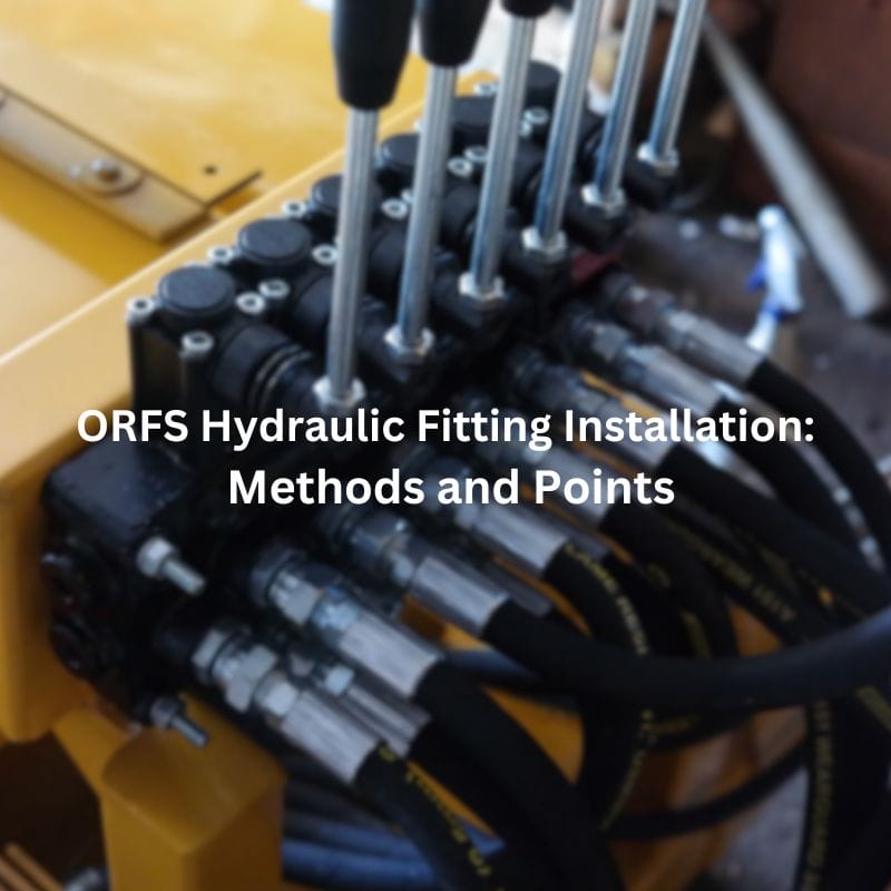
ORFS Hydraulic Fitting Installation: Methods and Points

Introduction

O-Ring Face Seal hydraulic fittings are a type of connection used in hydraulic systems to ensure a leak-free seal. They feature an O-ring in the face of the fitting that, when compressed, provides a secure seal. This design makes ORFS fittings particularly reliable in high-pressure environments, offering superior leak resistance compared to other types of fittings. The primary purpose of this post is to offer a comprehensive guide on the installation methods for ORFS hydraulic fittings. By providing step-by-step instructions, this post aims to equip technicians and engineers with the knowledge needed to install these fittings correctly, ensuring a secure and reliable connection in their hydraulic systems.

Understanding ORFS Hydraulic Fittings

What are ORFS Hydraulic Fittings?

ORFS hydraulic fittings are designed to provide a robust, leak-free connection in hydraulic systems. These fittings consist of a flat face with a groove that holds an O-ring, which is compressed against a mating surface when the fitting is tightened. This design ensures a secure seal that can withstand high pressures. The fittings are typically made from durable materials such as stainless steel, brass, or carbon steel, which enhance their longevity and resistance to corrosion. The precise engineering of the O-ring groove and the use of high-quality O-rings are crucial for maintaining the integrity of the seal under various operating conditions.

ORFS hydraulic thread Topa

How They Differ from Other Fittings

ORFS fittings are distinct from other types of hydraulic fittings due to their unique sealing mechanism. Unlike flare fittings, which rely on metal-to-metal contact, ORFS fittings use an elastomeric O-ring to create the seal. This difference allows ORFS fittings to provide a more reliable and leak-proof connection, especially in high-pressure applications. Additionally, ORFS fittings are easier to install and do not require precise torque settings, unlike compression fittings, which need exact installation procedures to avoid leaks. The versatility and ease of use make ORFS fittings a popular choice for many hydraulic applications.

Leak Prevention

One of the primary advantages of ORFS hydraulic fittings is their exceptional ability to prevent leaks. The O-ring seal effectively blocks any potential escape paths for hydraulic fluid, ensuring a tight and secure connection. This feature is particularly beneficial in applications where even minor leaks can lead to significant performance issues or safety hazards. By minimizing the risk of leaks, ORFS fittings help maintain system efficiency and reduce maintenance costs.

High-Pressure Handling

ORFS fittings are designed to handle high-pressure environments, making them suitable for demanding hydraulic applications. The O-ring face seal is capable of maintaining its integrity under extreme pressure, preventing blowouts, and ensuring reliable performance. This capability is crucial in industries where hydraulic systems operate under intense pressure, such as in heavy machinery, industrial equipment, and aerospace applications. The high-pressure handling characteristic of ORFS fittings contributes to their widespread adoption in these sectors.

Durability and Reliability

The materials and design of ORFS fittings contribute to their durability and long-term reliability. Constructed from high-strength metals, these fittings can withstand harsh operating conditions, including exposure to corrosive fluids and extreme temperatures. The O-ring, typically made from resilient materials like Viton or nitrile rubber, ensures a lasting seal that remains effective over time. This durability reduces the need for frequent replacements and repairs, providing a cost-effective solution for maintaining hydraulic systems.

Common Types and Sizes

ORFS hydraulic fittings come in various types to suit different application requirements. The most common types include:

Male ORFS Fittings: These fittings have an external thread and an O-ring face, designed to mate with female fittings.

Female ORFS Fittings: These fittings have an internal thread and a flat sealing face with an O-ring groove, designed to mate with male fittings.

Adjustable ORFS Fittings: These fittings allow for flexibility in alignment, making them ideal for applications where precise positioning is required. They typically feature a swivel nut that enables easy adjustment without compromising the seal.

Size Standards and Selection Criteria

ORFS fittings are available in a range of sizes to accommodate various hydraulic system requirements. The sizes are typically standardized according to industry norms, such as SAE (Society of Automotive Engineers) or ISO (International Organization for Standardization) specifications. When selecting ORFS fittings, it is essential to consider factors such as the system’s pressure rating, fluid type, and temperature range. Proper sizing ensures compatibility and optimal performance, preventing issues such as over-tightening or insufficient sealing. Consulting manufacturer guidelines and industry standards can help in choosing the right ORFS fittings for specific applications, ensuring a secure and efficient hydraulic system.

How O-Ring Face Seal Works

The effectiveness of ORFS fittings is based on their unique sealing mechanism, which relies on an elastomeric O-ring compressed between two flat surfaces. This engineering approach provides superior leak prevention compared to traditional metal-to-metal seals.

Flat Face Design

Unlike flare fittings, which depend on a metal-to-metal contact for sealing, ORFS fittings feature a flat face on both the male and female ends. The male end has a recessed groove that holds the O-ring, ensuring it remains in place during installation and operation.

Compression Sealing Mechanism

When the ORFS fitting is tightened, the O-ring is compressed between the flat surfaces, creating a secure and uniform seal. This compression ensures that the sealing integrity remains intact even under extreme pressure variations and mechanical vibrations.

High Resistance to Vibration and Pressure

Traditional hydraulic fittings often fail due to vibrations causing loosening or fatigue cracks. ORFS fittings, however, provide a more stable connection because the O-ring absorbs vibrations and maintains the seal without relying on excessive tightening. This makes them highly suitable for applications in heavy-duty machinery, mobile hydraulic systems, and industrial equipment.

Reduced Risk of Over-Tightening

Unlike metal-to-metal seals, which require high torque for proper sealing, ORFS fittings achieve optimal sealing with controlled compression. This reduces the risk of over-tightening, which can lead to thread damage or deformation of sealing surfaces.

O-Ring Material Options and Implications

The choice of O-ring material is crucial in ORFS fittings, as it determines the fitting’s resistance to temperature, pressure, and chemical exposure. Different applications require specific O-ring materials to ensure compatibility with hydraulic fluids, environmental conditions, and operational stress.

O-Ring Material

Temperature
Range(℃)

Key Features

Best Suited Applications

Nitrile(NBR)

-40 to 120

Good resistance to oil and fuel, cost-effective

General hydraulic systems, automotive,industrial machinery

Fluorocarbon (VitonR)

-20 to 200

Excellent chemical and heat resistance

Aerospace,high-temperature hydraulic systems, aggressive fluids

Ethylene Propylene
(EPDM)

-50 to 150

Good resistance to water, steam, and brake fluids

Water-based hydraulic systems, automotive brake systems

Silicone

-60 to 230

Excellent flexibility in extreme temperatures

Medical equipment, food-grade applications

Polytetrafluoroethylene
(PTFE)

-200 to 250

Chemically inert,high-temperature resistant

Chemical processing, aerospace, corrosive fluid handling

Implications of O-Ring Material Selection

Temperature Resistance: Choosing the wrong O-ring material for a high-temperature environment can cause premature degradation and leaks. For example, Nitrile (NBR) may harden and crack under extreme heat, whereas Fluorocarbon (Viton®) would be more suitable.

Chemical Compatibility: Hydraulic fluids vary in composition, and some may degrade standard rubber O-rings. EPDM, for example, is ideal for water-based fluids but is incompatible with petroleum-based oils.

Seal Longevity and Maintenance: Proper material selection can significantly extend the service life of the fitting, reducing maintenance costs and downtime. Using an incompatible O-ring material can lead to frequent replacements and system failures.

Preparation for Installation

Selecting ORFS Fittings

Choosing the right O-Ring Face Seal (ORFS) fitting is crucial for ensuring a reliable, leak-free hydraulic system. Several key factors must be considered when selecting ORFS fittings, including adjustability, material, size, and thread type.  

Adjustable and Fixed Face Seal Fittings

ORFS fittings come in two main types: adjustable and fixed face seal fittings. Understanding their differences is essential for proper selection based on the application.

Adjustable ORFS Fittings:

Feature a locknut and washer that allow rotational adjustment before final tightening.

Ideal for applications requiring precise alignment, such as multi-hose hydraulic systems.

Commonly used in environments where space constraints make fixed fittings difficult to install.

Fixed ORFS Fittings:

Have a solid, non-rotating connection between the fitting and the hose or pipe.

Provide superior strength and durability in high-pressure applications.

Best suited for systems where alignment is predetermined, and flexibility in positioning is not required.

List of Required Tools

To ensure a successful installation of ORFS hydraulic fittings, having the right tools is crucial. The following tools are commonly required:

Wrenches: Adjustable wrenches and specific-sized wrenches suitable for the fittings being installed.

Torque Wrenches: Essential for applying the correct torque to ensure proper sealing without over-tightening.

Pipe Cutters: For cutting hydraulic hoses or pipes to the required lengths.

Deburring Tools: To smooth out any rough edges on cut pipes or hoses.

Calipers or Micrometers: For precise measurement of fitting dimensions to ensure compatibility.

Hose Crimping Tools: For fittings that require crimping onto hydraulic hoses.

Hydraulic Pressure Test Kits: To test the system after installation and ensure there are no leaks.

Materials Needed

In addition to tools, specific materials are necessary to facilitate the installation process and ensure a secure connection:

Sealants: Thread sealants or pipe dope to ensure a tight seal on threaded connections.

Lubricants: Hydraulic oil or specific lubricants to ease the fitting installation and prevent O-ring damage.

O-rings: Spare O-rings of the correct size and material (e.g., Viton, nitrile) in case replacements are needed.

Cleaning Solvents: Isopropyl alcohol or other suitable solvents for cleaning components before installation.

Protective Caps: To keep the fittings clean and free from contaminants until they are installed.

ORFS Hydraulic Fitting Installation

Installation Methods

Positioning the Fitting

The first step in installing an ORFS hydraulic fitting is positioning the fitting correctly. Begin by identifying the exact location where the fitting will be installed. Ensure that the hydraulic hose or pipe is cut to the appropriate length and that the ends are clean and free of burrs. Position the fitting so that it aligns correctly with the hose or pipe, ensuring that the O-ring face will mate properly with the corresponding surface. Correct positioning is crucial for avoiding misalignment, which can lead to leaks or system inefficiencies.

Lubricating Components

Proper lubrication of ORFS fittings is essential to prevent O-ring damage and ensure smooth assembly.

Select the Right Lubricant

Use a compatible hydraulic oil or manufacturer-recommended O-ring lubricant.

Avoid petroleum-based lubricants if the O-ring material is not resistant to them.

Apply Lubricant Evenly

Lightly coat the O-ring with lubricant to reduce friction and prevent pinching during installation.

Ensure the lubricant is evenly distributed without excessive buildup.

Lubricate Threaded Components (If Required)

Apply a small lubricant to the threads to ease tightening and reduce wear.

Do not over-lubricate, as excess oil can attract contaminants.

Proper Alignment Techniques

Proper alignment is essential for creating a secure and leak-free connection. Align the fitting so that the O-ring face is perpendicular to the mating surface. Use visual inspection and measuring tools such as calipers to ensure that the fitting is centered and aligned correctly. For hoses, make sure they are not twisted or kinked, as this can affect the alignment and the integrity of the seal. Correct alignment minimizes stress on the fitting and the O-ring, ensuring a durable connection.

Hand-tightening and Initial Alignment

Once the fitting is positioned and aligned, begin the installation by hand-tightening the nut. This step ensures that the fitting is correctly aligned before applying torque. Hand-tightening allows you to feel if the threads are engaging properly and help prevent cross-threading. Rotate the nut by hand until it is snug but not overly tight. At this stage, check the alignment again to ensure that it has not shifted during hand-tightening.

Final Tightening Using Torque Tools

The final tightening step involves using a torque wrench to apply the correct amount of torque to the fitting. Refer to the manufacturer’s specifications for the recommended torque values. Using a torque wrench, tighten the nut to the specified torque, ensuring that the O-ring is properly compressed to create a secure seal. Avoid over-tightening, as this can damage the O-ring and the fitting. Apply the torque gradually, checking alignment and fit as you go. Once the correct torque is reached, the installation is complete.

Ensuring Proper Seal and Fit

Use of Sealants and Lubricants

Using sealants and lubricants can enhance the sealing capability and ease the installation process. Apply a small amount of hydraulic oil or a compatible lubricant to the O-ring and the threads of the fitting. This reduces friction and prevents damage to the O-ring during tightening. For threaded connections, use an appropriate thread sealant or pipe dope to ensure a leak-free connection. Ensure that the sealant is compatible with the hydraulic fluid used in the system.

Checking for Leaks and Making Adjustments

After completing the installation, it is essential to check for leaks. Pressurize the hydraulic system and inspect the fitting for any signs of fluid leakage. If a leak is detected, depressurize the system and make the necessary adjustments. This may involve re-tightening the fitting, adjusting the alignment, or replacing the O-ring. Ensure that all adjustments are made carefully to avoid damaging the components. A leak-free installation is crucial for the reliability and safety of the hydraulic system.

Post-Installation Checks

After installation, a final inspection ensures the fitting is secure and ready for operation.

Check for Leaks

Perform a visual inspection to confirm no hydraulic fluid is seeping around the fitting.

If available, use a leak detection solution for more precise checking.

Conduct a Pressure Test

Gradually pressurize the system while monitoring the fitting for leaks.

If a leak is detected, relieve the pressure, inspect the O-ring, and re-tighten the fitting if necessary.

Confirm Proper Hose Routing

Ensure the connected hose has no excessive bends or twists.

Verify that the hose is properly supported to prevent vibration-induced loosening.

Common Challenges and Solutions

Even with careful preparation and attention to detail, mistakes can happen when connecting brass pipe fittings. Understanding common errors and knowing how to troubleshoot them can help ensure a secure and leak-free installation. Here are some common mistakes and troubleshooting tips:

Addressing Misalignment Issues

Causes and Prevention

Misalignment of ORFS hydraulic fittings can lead to leaks, premature wear, and system inefficiencies. Common causes of misalignment include improper positioning of components, twisting or bending of hoses during installation, and incorrect alignment of mating surfaces. To prevent misalignment:

Ensure that all components are correctly positioned before beginning the installation.

Avoid twisting or kinking hoses; use hose supports or clamps to maintain proper alignment.

Use alignment tools and visual inspection to confirm that fittings are perpendicular to mating surfaces.

Corrective Measures

If misalignment occurs, it can be corrected through several methods:

Loosen the fitting and realign the components carefully, ensuring they are properly positioned.

Use alignment tools or jigs to hold components in place during tightening.

Replace hoses or pipes that are twisted or bent beyond repair.

For severe misalignment, consider redesigning the system layout to improve alignment and reduce stress on fittings.

Dealing with Over-tightening and Under-tightening

Recognizing the Signs

Over-tightening and under-tightening can both cause significant issues in hydraulic systems. Signs of over-tightening include:

Crushed or damaged O-rings

  • Deformed fittings or threads
  • Difficulty in loosening fittings during maintenance
  • Signs of under-tightening include:
  • Leaks at the fitting connections
  • Loose fittings that can be moved by hand
  • Incomplete engagement of threads

Proper Torque Application Techniques

Applying the correct torque is crucial for ensuring a secure and leak-free connection:

  • Always use a calibrated torque wrench to apply the specified torque values provided by the manufacturer.
  • Gradually tighten the fitting, using a crisscross pattern if applicable, to evenly distribute the load.
  • Avoid using excessive force; if the specified torque is reached and the fitting is still loose, check for alignment issues or thread damage.
  • Periodically check and recalibrate torque wrenches to ensure accuracy.
Hydraulic Fittings environment

Preventing and Fixing Leaks

Leaks in hydraulic systems can originate from several sources:

  • Damaged or improperly seated O-rings
  • Cracks or deformities in fittings or hoses
  • Loose or improperly tightened fittings
  • Contaminants or debris in the sealing surfaces

To identify leak sources:

  • Inspect the system visually for signs of hydraulic fluid around fittings and connections.
  • Use a hydraulic pressure test kit to pinpoint the exact location of leaks.
  • Check O-rings and sealing surfaces for damage or contamination.

Effective Repair Methods

  • Once a leak source is identified, take the following steps to fix it:
  • Replace damaged O-rings with new ones of the correct size and material.
  • Clean sealing surfaces thoroughly to remove any contaminants or debris.
  • Tighten loose fittings to the specified torque using a torque wrench.
  • Replace cracked or deformed fittings and hoses with new components.
  • If the leak persists, re-evaluate the system design and installation procedures to identify and address underlying issues.

System Vibration Causing Loosening

Problem:

Hydraulic systems, especially those in mobile or heavy machinery, experience constant vibrations. Over time, these vibrations can cause ORFS fittings to loosen, leading to leaks and potential system failure.

Causes:

Insufficient tightening during installation.

Continuous mechanical vibrations cause gradual loosening.

Misaligned hose routing puts excessive strain on fittings.

Solutions:

Ensure Proper Torque Application – Use a torque wrench and follow manufacturer specifications when tightening ORFS fittings. Under-tightening can allow fittings to loosen, while over-tightening can damage threads and O-rings.

Use Locking Mechanisms – Consider using hydraulic thread-locking compounds or locknuts to prevent fittings from loosening due to vibration.

Improve Hose Routing – Ensure hoses are correctly routed with enough flexibility to absorb movement. Avoid sharp bends or excessive tension on the fittings.

Install Vibration Dampeners – If vibrations are excessive, adding dampeners or flexible hose supports can minimize movement and reduce the risk of fittings loosening.

High Temperature Leading to O-Ring Failure  

Problem:

Exposure to high temperatures can cause O-rings to harden, crack, or lose their elasticity, leading to seal failure and leaks.

Causes:

Continuous exposure to elevated fluid or ambient temperatures.

Using O-rings made from materials with low heat resistance.

High-pressure operation increases internal temperature and accelerates O-ring degradation.

Solutions:

Use High-Temperature O-Rings – Choose materials designed for extreme temperatures:

Viton (FKM): Works well up to 200°C (392°F), making it ideal for high-heat applications.

PTFE (Teflon): Provides superior resistance to both high temperatures and aggressive chemicals.

Install Heat Shields or Insulation – In environments with excessive external heat (e.g., near engines or exhaust systems), use protective insulation or heat shields to reduce temperature exposure.

Monitor System Temperature – Use temperature sensors to track heat levels and prevent exceeding the O-ring’s operating limits.

Implement Fluid Cooling Solutions – If hydraulic fluid temperatures are too high, consider installing additional cooling components, such as heat exchangers or cooling fans.

Maintenance Tips to Prevent Leaks

Regular Inspection Schedule

Regular inspections are crucial for detecting early signs of wear, misalignment, or improper sealing. A structured inspection routine can help identify potential issues before they lead to leaks or system failures.

Inspection Frequency

Daily or Weekly:

Check for visible leaks around ORFS fittings.

Inspect for loose connections due to system vibrations.

Look for signs of fluid residue near fittings, which may indicate a slow leak.

Monthly or Quarterly:

Examine O-rings for any signs of wear, deformation, or cracking.

Verify proper hose routing to ensure fittings are not under excessive strain.

Ensure fittings are properly tightened according to manufacturer specifications.

Annually:

Conduct a full system check, including pressure testing, to identify any weak seals.

Replace all O-rings as part of preventive maintenance, even if no leaks are detected.

Inspection Tip: Use a flashlight and mirror to inspect hard-to-reach fittings. If leaks are suspected, apply a leak detection solution to confirm.

Replace Worn O-Rings

O-rings are critical to the sealing performance of ORFS fittings, and their deterioration is a common cause of leaks. Regular replacement ensures continued leak-free operation.

When to Replace O-Rings

Visible Damage: If an O-ring appears cracked, flattened, or deformed.

Frequent Adjustments: If a fitting has been loosened and retightened multiple times.

System Leaks: If hydraulic fluid is detected around the fitting, and re-tightening does not resolve the issue.

Time-Based Replacement: Even if no leaks are present, replacing O-rings annually as a preventive measure is recommended.

How to Replace an O-Ring Properly

Depressurize the System – Ensure all pressure is released before disassembling the fitting.

Remove the Old O-Ring – Use a plastic pick or non-metallic tool to avoid scratching the sealing surface.

Clean the Groove and Fitting – Remove dirt and debris using a lint-free cloth and an approved hydraulic cleaner.

Lubricate the New O-Ring – Apply a thin layer of compatible hydraulic oil or manufacturer-approved lubricant.

Install the New O-Ring – Ensure it is seated evenly in the groove without twisting or stretching.

Replacement Tip: Always use O-rings made from materials compatible with the hydraulic fluid in your system (e.g., Nitrile for petroleum-based fluids, Viton for high-temperature applications).

Avoid Over-Tightening

Over-tightening ORFS fittings is a common mistake that can damage the O-ring, deform the sealing face, and lead to leaks.

Consequences of Over-Tightening

O-Ring Compression Damage: Excessive pressure can cause the O-ring to extrude beyond its sealing groove, reducing its effectiveness.

Thread Galling or Stripping: High torque can damage the fitting threads, making it difficult to reassemble or replace components.

Surface Deformation: The sealing face may warp, preventing a proper seal even after O-ring replacement.

Proper Tightening Procedure

Hand-Tighten First – Align the fitting and tighten it by hand to ensure correct seating.

Use a Torque Wrench – Follow manufacturer torque specifications rather than relying on force.

Tighten in Increments – Apply gradual torque, stopping to check for proper sealing.

Check for Leaks – If a fitting still leaks after proper tightening, inspect the O-ring and contact surfaces instead of applying excessive force.

Conclusion

This guide provides detailed methods and tips that emphasize the importance of meticulous installation practices, from positioning and alignment to proper torque application and leak prevention. By adhering to these best practices, you can greatly reduce the risk of leaks and system failures and ensure that your hydraulic system is built to last. We invite you to share your experiences, feedback, and any questions you may have, Topa is always at your service.

FAQ

ORFS (O-Ring Face Seal) hydraulic fittings use an O-ring seated in a groove on the fitting’s face to create a leak-free seal, ideal for high-pressure applications.

Use visual inspection and alignment tools to ensure the fitting faces are perpendicular and properly aligned before tightening. Avoid twisting or kinking hoses during installation.

Refer to the manufacturer’s specifications for the correct torque values. Always use a calibrated torque wrench to apply the specified torque to prevent over-tightening or under-tightening.

You will need wrenches, torque wrenches, lubricants, sealants, and O-rings. Ensure you have all necessary tools and materials before starting the installation process.

Ensure proper alignment, use the correct torque, and apply appropriate sealants and lubricants. Regularly inspect O-rings and sealing surfaces for damage or contaminants.

Depressurize the system, inspect and replace damaged O-rings, clean the sealing surfaces, and retighten the fitting to the specified torque. If the leak persists, check for alignment issues or replace faulty components.

More Posts

ORFS Fittings Meaning Everything You Need to Know

ORFS Fittings Meaning: Everything You Need to Know

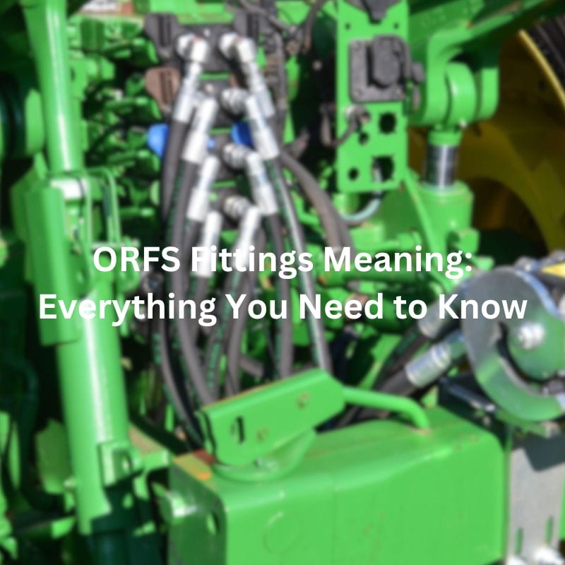
ORFS Fittings Meaning: Everything You Need to Know

Table of Contents

Introduction

Hydraulic fittings are essential components in hydraulic systems, connecting various parts to ensure the seamless flow of hydraulic fluid. Among the numerous types of hydraulic fittings, O-Ring Face Seal fittings stand out due to their unique design and exceptional performance. These fittings utilize an O-ring mechanism to create a secure, leak-proof seal, making them indispensable in high-pressure applications. This article aims to provide a comprehensive overview of ORFS fittings, their functionality, benefits, and applications, equipping readers with the knowledge needed to make informed decisions in their hydraulic projects.

What are ORFS Fittings?

Definition of ORFS Fittings

ORFS (O-Ring Face Seal) fittings are specialized hydraulic connectors designed to provide a secure and leak-proof seal in high-pressure applications. The defining feature of these fittings is the incorporation of an O-ring, which is positioned in the face of the fitting. When connected, the O-ring is compressed between the fitting and its counterpart, creating a robust seal that prevents hydraulic fluid leaks.

Historical Background and Development

The development of ORFS fittings can be traced back to the mid-20th century when the demand for more reliable hydraulic systems in industrial and military applications grew significantly. Engineers and manufacturers sought to design fittings that could withstand higher pressures and more extreme conditions than traditional fittings. This need led to the creation of the ORFS design, which has since become a standard in various high-performance hydraulic systems due to its superior sealing capabilities.

ORFS connection

Key Characteristics and Features

O-ring Face Seal Design

The O-ring face seal design is the hallmark of ORFS fittings. This design ensures that when the fitting is tightened, the O-ring is compressed evenly, creating a high-integrity seal. This method significantly reduces the risk of leaks compared to threaded or metal-to-metal seal fittings. The O-ring material is typically chosen based on the fluid and temperature conditions it will encounter, ensuring compatibility and longevity.

Materials Used

ORFS fittings are commonly manufactured from robust materials to handle the demands of high-pressure systems. The most frequently used materials include:

  • Stainless Steel: Known for its corrosion resistance and strength, stainless steel is ideal for applications involving harsh environments or corrosive fluids.
  • Brass: Often used in less demanding environments, brass provides good corrosion resistance and is suitable for many general hydraulic applications.
  • Carbon Steel: This material offers excellent strength and durability for high-pressure applications but may require protective coatings to prevent corrosion.

Sizes and Dimensions

ORFS fittings are available in a wide range of sizes to accommodate different hydraulic systems and applications. Standard sizes typically range from 1/8 inch to 2 inches in diameter. The dimensions of ORFS fittings are standardized to ensure compatibility across various manufacturers and systems. This standardization facilitates easy replacement and interchangeability, contributing to the overall efficiency and reliability of hydraulic systems.

How ORFS Fittings Work

Explanation of the Sealing Mechanism

O-Ring Face Seal fittings are engineered to provide a reliable, leak-free connection in hydraulic systems. The primary sealing mechanism involves an O-ring that sits in a groove on the face of the fitting. When the fitting is tightened, the O-ring is compressed against the mating surface, creating a tight seal. This design ensures that the seal is maintained under high pressure and vibration, which are common in hydraulic systems. The O-ring’s flexibility allows it to adapt to minor surface imperfections, ensuring a consistent seal even if the mating surfaces are not perfectly smooth.

The Role of the O-ring in Preventing Leaks

The O-ring is the critical component in the ORFS fitting’s ability to prevent leaks. Made from materials like nitrile rubber (NBR), fluorocarbon (Viton), or ethylene propylene diene monomer (EPDM), the O-ring is chosen based on the specific requirements of the hydraulic fluid and operating temperature. When the ORFS fitting is assembled, the O-ring is compressed, filling the gap between the fitting faces and creating a barrier that prevents hydraulic fluid from escaping. This compression also absorbs shock and vibration, which further reduces the likelihood of leaks over time. The O-ring’s resilience and ability to maintain its shape under pressure make it an effective seal in demanding environments.

Typical Applications and Industries

Due to their superior sealing capabilities, ORFS fittings are widely used in industries where high pressure and reliability are critical. Some typical applications and industries include:

Agriculture

Agricultural machinery, such as tractors and harvesters, rely on hydraulic systems for operation. ORFS fittings provide the durability and leak-free performance needed to withstand the demanding conditions of agricultural work.

Construction

Construction equipment, including excavators, loaders, and cranes, use ORFS fittings in their hydraulic systems to ensure reliable performance under heavy loads and constant movement.

Industrial Manufacturing

In manufacturing plants, hydraulic systems power machinery and robotics. ORFS fittings help maintain consistent pressure and prevent leaks, ensuring smooth operation and reducing downtime.

Marine

Marine applications, such as hydraulic steering and winch systems, benefit from ORFS fittings’ ability to resist corrosion and maintain a leak-free seal in harsh, saltwater environments.

Automotive

High-performance and heavy-duty vehicles, including trucks and construction vehicles, use ORFS fittings in their hydraulic systems for braking, steering, and suspension components, ensuring reliable operation under demanding conditions.

Comparison with Other Types of Fittings

ORFS fittings are often compared with other types of hydraulic fittings, such as JIC (Joint Industry Council), NPT (National Pipe Thread), and BSP (British Standard Pipe). Each of these fittings has unique characteristics and applications, as well as distinct sealing mechanisms.

JIC vs NPT vs BSP

JIC Fittings

Characteristics: JIC fittings, developed by the Joint Industry Council, are known for their 37-degree flare seating surface. They are widely used in various hydraulic applications due to their robustness and versatility. JIC fittings are typically made from materials like stainless steel, brass, and carbon steel, providing durability and resistance to corrosion.

Sealing Mechanism: The sealing in JIC fittings is achieved through a metal-to-metal seal. The tubing is flared at a 37-degree angle and mates with the nose of the fitting, creating a seal when the connection is tightened. This metal-to-metal contact provides a strong and reliable seal under moderate pressure and vibration. However, the seal’s effectiveness depends on the quality of the flare and the surface finish of the mating components. In high-pressure or highly dynamic environments, JIC fittings may not provide as reliable a seal as ORFS fittings due to potential imperfections in the metal surfaces.

NPT Fittings

Characteristics: NPT fittings, or National Pipe Thread fittings, are widely used in North America for various plumbing and hydraulic applications. NPT fittings have a tapered thread design, which increases the interference fit as the connection is tightened. These fittings are commonly made from materials such as stainless steel, brass, and carbon steel.

Sealing Mechanism: The primary sealing mechanism in NPT fittings is the interference created by the tapered threads. As the fitting is tightened, the threads compress against each other, creating a seal. However, due to the nature of thread engagement, NPT fittings often require additional sealing aids like thread sealant or Teflon tape to ensure a leak-free connection. This reliance on supplementary sealing methods can be a disadvantage in high-pressure applications, where the risk of leaks and thread damage is higher compared to the O-ring seal in ORFS fittings. Furthermore, NPT fittings can be more challenging to install correctly, as over-tightening can damage the threads and under-tightening can result in leaks.

BSP Fittings

Characteristics: BSP (British Standard Pipe) fittings are commonly used in Europe and other parts of the world. BSP fittings come in two main types: BSPP (British Standard Pipe Parallel) and BSPT (British Standard Pipe Tapered). BSPP fittings have parallel threads, while BSPT fittings have tapered threads. These fittings are typically manufactured from stainless steel, brass, and carbon steel, offering good resistance to corrosion and durability.

Sealing Mechanism:

  • BSPP Fittings: BSPP fittings use parallel threads and typically rely on a bonded seal or an O-ring to create a seal. The O-ring is placed in a groove on the fitting, and when the fitting is tightened, the O-ring is compressed against the mating surface, forming a seal. This sealing mechanism is somewhat similar to ORFS fittings but may not provide the same level of reliability and ease of maintenance.
  • BSPT Fittings: BSPT fittings use tapered threads to create a seal through thread interference, similar to NPT fittings. The threads compress against each other as the fitting is tightened, creating a seal. Like NPT fittings, BSPT fittings may require additional sealing aids like thread sealant or Teflon tape to ensure a leak-free connection. The effectiveness of the seal depends on the precision of the thread engagement, and over-tightening or under-tightening can result in leaks or thread damage.

ORFS vs ORB (O-Ring Boss)

Definition: ORB (O-Ring Boss) fittings, on the other hand, seal via an O-ring seated in a chamfered groove at the base of the male thread. The O-ring compresses against a machined flat surface inside the female port, creating a seal at the boss (bottom of the thread).

Thread Engagement: ORFS typically uses straight threads (SAE J1453) with a face seal, while ORB also uses straight threads (SAE J514) but relies on sealing at the thread base rather than the face.

Pressure & Vibration Resistance: ORB is effective for many applications, but under extreme vibration or repeated torque cycles, seal failure or loosening may occur more frequently than with ORFS.

ORFS vs Metric DIN

Standard Overview:Metric DIN fittings are standardized under DIN 2353 and ISO 8434-1. They use a 24° cone inside the female fitting and a corresponding cutting ring or flare to seal with the male fitting.

Metric DIN fittings come in two pressure categories:

Light Series (L): for medium-pressure applications.

Heavy Series (S): for high-pressure systems.

Sealing Mechanism: DIN fittings seal via metal-to-metal contact between the 24° cone and the ferrule/cutting ring.

Pressure Ratings:

ORFS typically handles up to 6,000 psi (414 bar), depending on size and material.

DIN Heavy Series can also reach similar pressures but is less tolerant to vibration due to the rigid metal-to-metal interface.

Types of ORFS Fittings

ORFS hydraulic fittings come in various configurations to meet the diverse needs of hydraulic systems. These fittings are designed to provide leak-free connections in high-pressure applications, and each type serves specific purposes. The main types of ORFS fittings include straight fittings, elbow fittings, tee fittings, and adapter fittings. Each type has unique applications, ensuring optimal performance and flexibility in different hydraulic systems.

ORFS Fitting Types

Straight Fittings

Characteristics and Uses:

Straight fittings are the simplest type of ORFS fittings, featuring a straight design that connects two hydraulic components in a linear fashion. These fittings are commonly used in situations where there is a need to join hoses or pipes without changing the direction of the flow. They are available in various sizes to accommodate different hydraulic system requirements.

Specific Applications:

Connecting hydraulic hoses to pumps or valves.

Extending hydraulic lines without altering the flow direction.

Used in systems where space constraints require a direct connection between components.

Elbow Fittings

Characteristics and Uses:

Elbow fittings are designed with a 45-degree or 90-degree bend, allowing the hydraulic flow to change direction. These fittings are crucial in systems where space constraints or design requirements necessitate a change in the flow direction. Elbow fittings help to maintain system efficiency and prevent hose kinking, which can lead to pressure drops and potential leaks.

Specific Applications:

Routing hydraulic lines around obstacles or within confined spaces.

Connecting hoses or pipes in machinery with complex geometries.

Used in hydraulic systems where directional changes are needed to optimize flow paths.

Tee Fittings

Characteristics and Uses:

Tee fittings feature a T-shaped design, allowing a single hydraulic flow to split into two separate lines or combine two flows into one. These fittings are essential for creating branches in hydraulic systems, enabling the distribution of hydraulic fluid to multiple components.

Specific Applications:

Dividing hydraulic fluid flow to power multiple actuators or cylinders.

Combining flows from different lines into a single return line.

Used in complex hydraulic systems where multiple functions are operated from a single fluid source.

Cross Fittings

Characteristics and Uses:

Cross fittings, also known as four-way fittings, feature a cross-shaped design that allows fluid to flow through four different points. This type of fitting is used when there is a need to split or combine hydraulic lines in four different directions. Cross fittings are essential in complex hydraulic circuits where multiple branches are necessary.

Specific Applications:

Distributing hydraulic fluid to multiple cylinders or actuators in machinery.

Creating intricate hydraulic circuits in industrial automation systems.

Used in hydraulic systems where multiple functions need to be powered from a single source, such as in agricultural equipment with multiple hydraulic attachments.

Crimped Fittings

Characteristics and Uses:

Crimped fittings are attached to hydraulic hoses using a crimping process, which permanently secures the fitting to the hose. These fittings provide a reliable and secure connection that is resistant to high pressure and vibration. Crimped fittings are widely used in applications where durability and safety are paramount.

Specific Applications:

High-pressure hydraulic systems in construction equipment, such as excavators and loaders.

Hydraulic systems in industrial machinery where frequent hose replacements are impractical.

Used in mobile equipment, such as trucks and heavy-duty vehicles, where reliable connections are essential for safety and performance.

Reusable Fittings

Characteristics and Uses:

Reusable fittings, also known as field attachable or screw-on fittings, can be attached to hydraulic hoses without the need for crimping equipment. These fittings can be easily removed and reattached, making them ideal for maintenance and repair applications. Reusable fittings provide flexibility and convenience, especially in field service scenarios.

Specific Applications:

Emergency repairs in hydraulic systems where immediate hose replacements are necessary.

Maintenance operations in remote locations where crimping equipment is unavailable.

Used in hydraulic systems that require frequent disassembly and reassembly, such as test rigs and prototypes.

Choosing the Right ORFS Fitting

Selecting the right ORFS (O-Ring Face Seal) fitting for your hydraulic system is crucial to ensure optimal performance, reliability, and safety. Several factors must be considered to make an informed decision.

Pressure Rating

Importance: Hydraulic systems operate under various pressure levels. Selecting a fitting that can withstand the system’s maximum pressure is essential to prevent leaks and ensure safety.

Considerations: Check the pressure rating of the ORFS fitting, typically provided by the manufacturer. Ensure it matches or exceeds the operating pressure of your hydraulic system.

Temperature

Importance: Hydraulic systems may be subjected to a wide range of temperatures, from extremely cold to very hot conditions. The fitting must be capable of performing reliably within this temperature range.

Considerations: Examine the temperature range specified for the ORFS fitting and ensure it aligns with the expected operating temperatures of your system. The O-ring material should also be suitable for these temperatures to maintain its sealing properties.

Fluid Type

Importance: The type of hydraulic fluid used in the system can affect the fitting’s performance and durability. Different fluids may have varying chemical properties that can interact with the fitting materials.

Considerations: Identify the type of hydraulic fluid (e.g., petroleum-based, synthetic, water-glycol) and ensure the ORFS fitting’s materials, including the O-ring, are compatible. Manufacturers often provide compatibility charts to help with this selection.

Compatibility with Existing Systems

Importance: Ensuring that the new ORFS fitting is compatible with your existing hydraulic system components is crucial for seamless integration and performance.

Considerations:

Thread Type and Size: Verify that the fitting’s threads match those of the existing components. Mismatched threads can cause leaks and damage to the system.

Material Compatibility: Ensure that the materials of the fitting are compatible with the existing system components to prevent galvanic corrosion or other adverse interactions.

Dimensional Fit: Check that the dimensions of the fitting align with the space and layout of your system to avoid installation issues.

Installing ORFS Fittings: A Step-by-Step Guide

Pre-Installation Checklist

  • Inspect all components for damage, dirt, or burrs
  • Ensure O-rings are compatible with fluid type and temperature
  • Verify that the fittings and ports are the correct size and thread type
  • Make sure O-rings are free of cracks, swelling, or flattening
  • Confirm that the system is depressurized and safe to work on
install ORFS fittings

Preparing for Installation

  • Clean the sealing surfaces with a lint-free cloth
  • Lightly lubricate the O-ring using a fluid-compatible lubricant
  • Align the fitting and mating surface to prevent cross-threading
  • Hand-tighten the fitting to ensure proper thread engagement
  • Avoid using sealant or Teflon tape on ORFS threads, as sealing occurs at the face

Torque Recommendations by Size

  • Use a calibrated torque wrench to avoid over-tightening
  • Follow manufacturer guidelines or typical torque values such as:

1/4″ fitting: 18–22 ft-lbs

1/2″ fitting: 45–60 ft-lbs

3/4″ fitting: 75–90 ft-lbs

1″ fitting: 100–110 ft-lbs

1-1/4″ and larger: Check technical manual for exact spec

  • Re-check torque after first system pressurization

Post-Installation Testing & Leak Checks

  • Pressurize the system slowly and monitor for leaks
  • Inspect the seal visually at the O-ring interface
  • Check for any signs of twisting or extrusion of the O-ring
  • If a leak is detected, depressurize the system and re-torque the fitting
  • Record torque and inspection results for maintenance logs

Maintenance & Troubleshooting of ORFS Fittings

Regular O-Ring Inspection

  • Schedule periodic visual inspections of O-rings at all ORFS connections
  • Look for signs of wear such as cracking, flattening, cuts, or hardening
  • Replace O-rings if they appear swollen or degraded due to fluid incompatibility
  • Ensure proper O-ring seating and cleanliness during reassembly
  • Use only O-rings made from materials compatible with system temperature and fluid type

System Pressure Monitoring

  • Regularly monitor system pressure against the rated maximum of each fitting
  • Install pressure gauges at critical points to detect spikes or drops
  • Investigate abnormal pressure fluctuations promptly to prevent seal failure
  • Use data logging if available to track pressure over time and identify trends
  • Ensure pressure relief valves are functioning properly to protect fittings

Common Issues: Leakage, Misalignment, Over-tightening

Leakage

  • Caused by damaged O-rings, improper torque, or contaminated sealing surfaces
  • Fix by inspecting and replacing the O-ring, cleaning mating surfaces, and re-torquing to spec

Misalignment

  • Occurs when fittings are not properly aligned during assembly
  • This can lead to uneven O-ring compression or fitting stress
  • Prevent by supporting hoses and tubing to reduce side loads on the fitting

Over-tightening

  • Can distort or crush the O-ring, compromising the seal
  • May damage the fitting threads or cause cracking
  • Use a torque wrench and follow manufacturer specifications during installation

Conclusion

In conclusion, ORFS fittings are essential for ensuring reliable, leak-free connections in high-pressure hydraulic systems. We explored their definition, key characteristics, working mechanism, and various types, highlighting their advantages over other fittings like JIC, NPT, and BSP. Understanding these fittings’ benefits, such as superior sealing and easy maintenance, is crucial for anyone involved in hydraulic applications. We encourage you to consider ORFS fittings for your hydraulic systems to enhance performance and reliability. For more information or to explore our range of high-quality ORFS fittings, please visit our website or contact us directly.

FAQ

ORFS stands for O-Ring Face Seal, a type of hydraulic fitting known for its reliable, leak-proof sealing mechanism using an O-ring.

ORFS fittings provide superior leak prevention, high-pressure capability, easy installation, and excellent durability in various hydraulic applications.

ORFS fittings are typically made from stainless steel, brass, and carbon steel, chosen for their durability and resistance to corrosion.

Unlike JIC fittings, which use a metal-to-metal seal, ORFS fittings use an O-ring face seal, offering better leak prevention and easier maintenance.

ORFS fittings are widely used in industries such as aerospace, agriculture, construction, industrial manufacturing, marine, and automotive.

Consider factors such as pressure rating, temperature range, fluid compatibility, thread type, and certification standards to ensure the fitting matches your system’s requirements.

More Posts

Contact Topa

Save 30% on maintenance costs with our easy-install hydraulic fittings. Contact Now!