
ORB Hydraulic Fitting Sizes: Everything You Must Know Contact Us
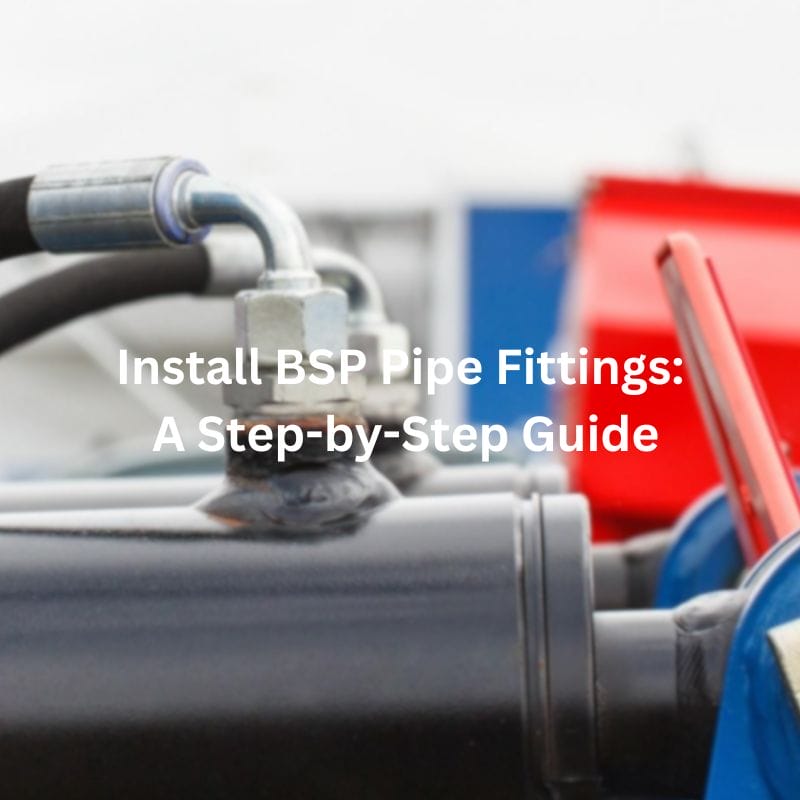
Install BSP Pipe Fittings: A Step-by-Step Guide Table of Contents
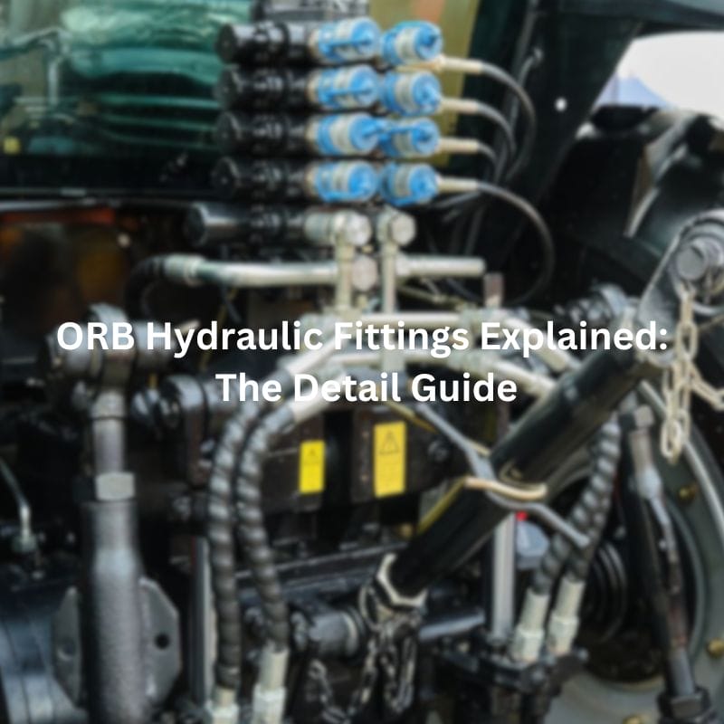
ORB Hydraulic Fittings Explained: The Detail Guide Contact Us Introduction
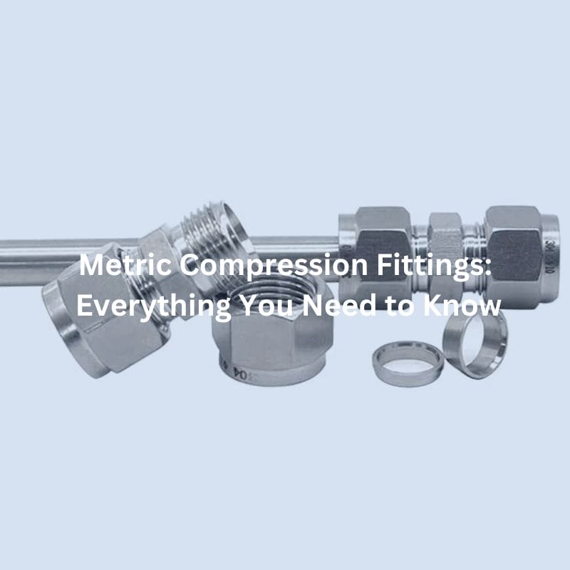
Metric Compression Fittings: Everything You Need to Know Contact Us

Install BSP Hose Fitting: Quick and Accurate Methods Table of

BSP Hydraulic Fittings Dimensions: Detailed Reference Guide Introduction BSP hydraulic

JIC Fitting Leaking: Causes and Solutions Contact Us Table of

What Does JIC Stand for in Hydraulic Fittings? Contact Us

Top Causes of BSP Hydraulic Fitting Leaking and Solutions Table