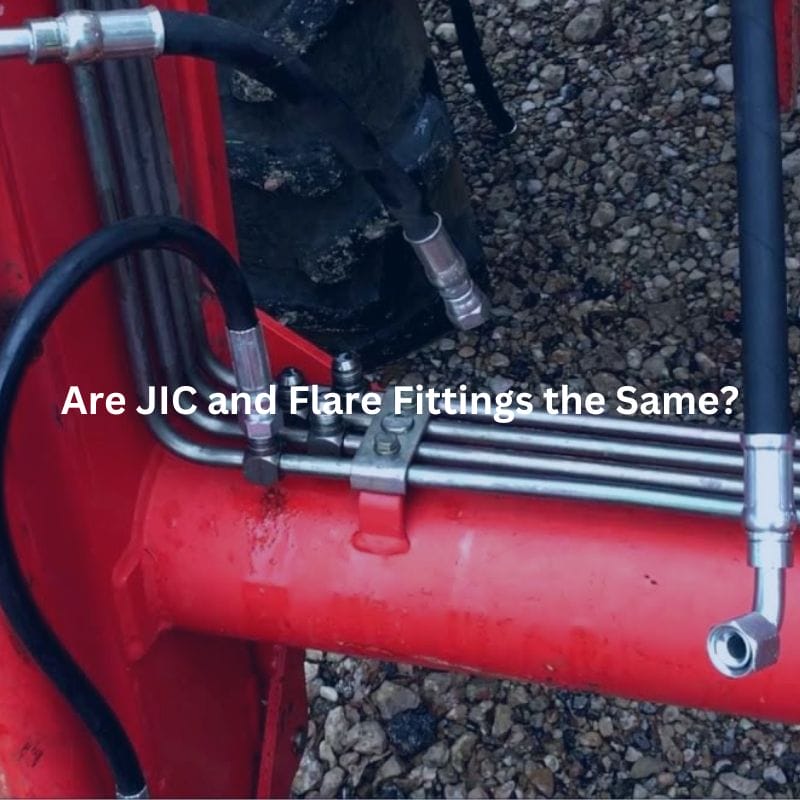
Are JIC and Flare Fittings the Same?
Are JIC and Flare Fittings the Same? Contact Us Introduction
Are JIC and Flare Fittings the Same? Contact Us Introduction
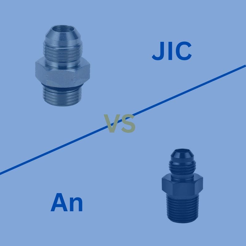
Are JIC and AN Fittings the Same? Contact Us Introduction
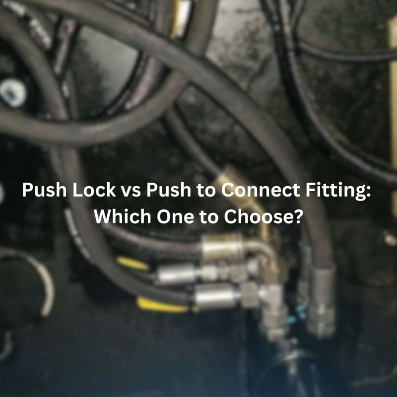
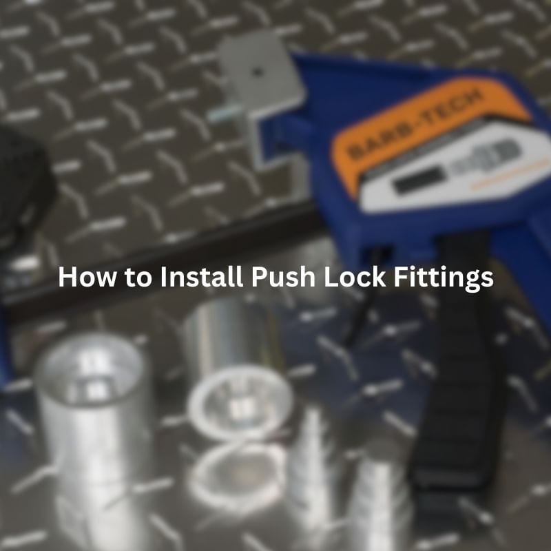
Push Lock vs Push to Connect Fitting: Which One to
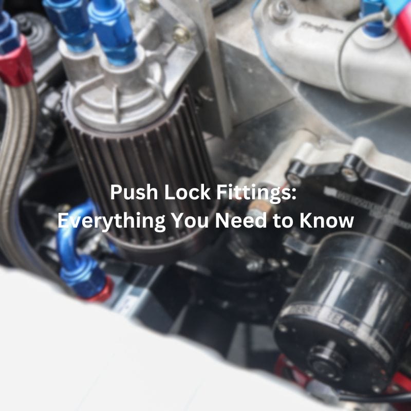
Push Lock Fittings: Everything You Need to Know Contact Us

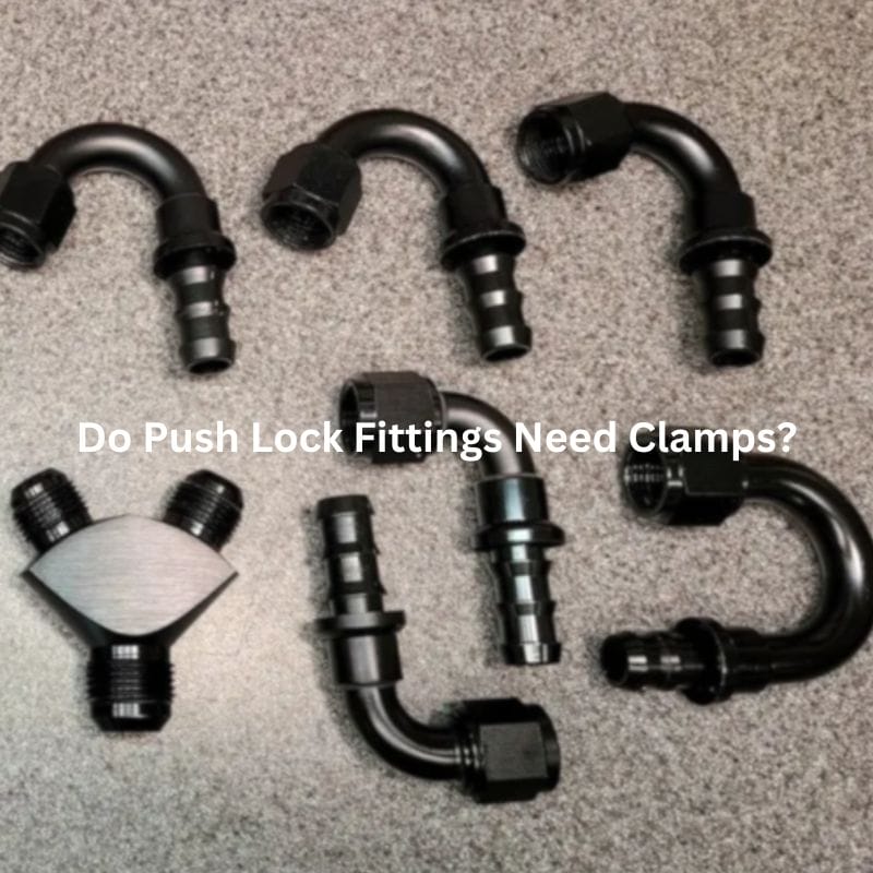
Do Push Lock Fittings Need Clamps? Contact Us Introduction Imagine
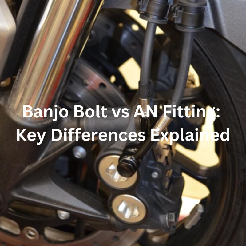
Banjo Bolt vs AN Fitting: Key Differences Explained Introduction Banjo
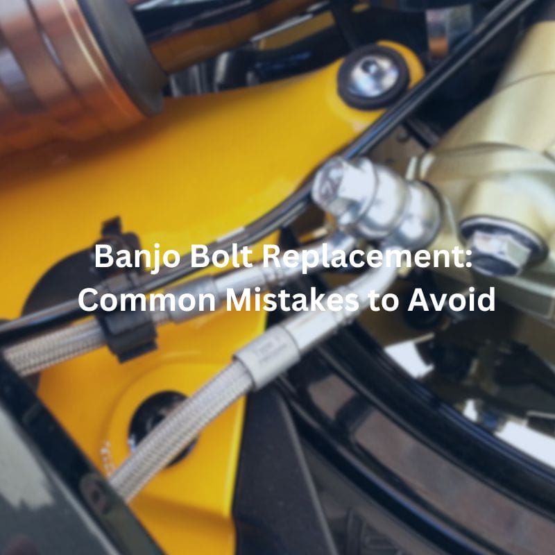
Banjo Bolt Replacement: Common Mistakes to Avoid Contact Us Table
Banjo Bolt Leaking? Discover Common Causes and Fixes Contact Us