How to Repair Damaged Threads in Hydraulic Fittings?
A single stripped thread stops your machine cold. The part
A single stripped thread stops your machine cold. The part

The cause of an O-ring failure is rarely obvious. You

In a harsh marine environment, a corroded hydraulic fitting isn’t
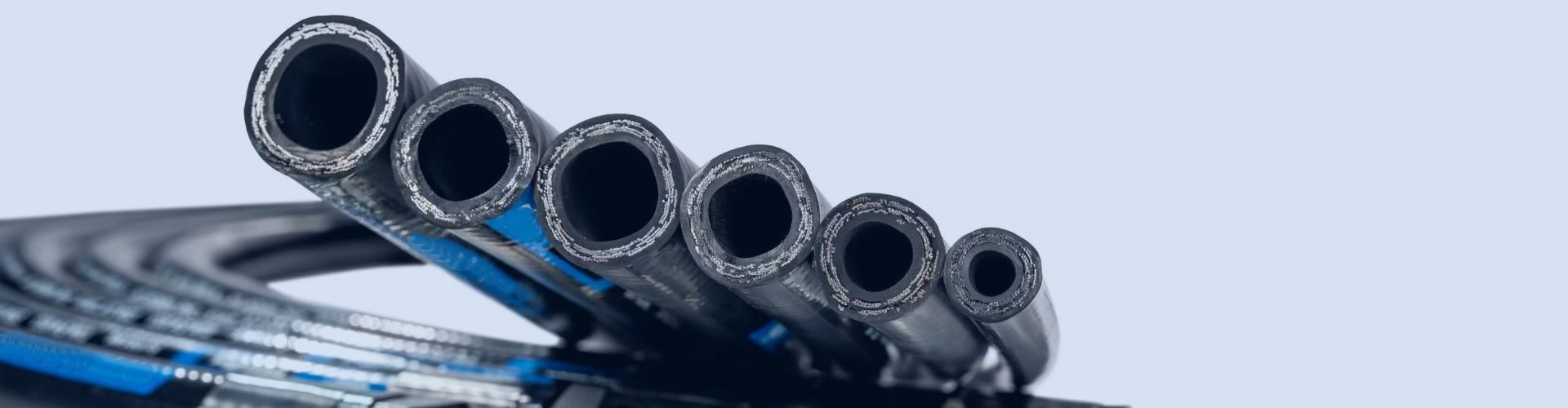
Choosing the wrong hydraulic hose is a serious problem. With
As a procurement manager, you face a constant dilemma. Using
As a procurement manager, you face a global puzzle. A
Selecting the wrong material for a hydraulic fitting is a
Field-attachable, or reusable hydraulic fittings are essential for any application
A truly reliable hydraulic fitting is the product of a
Your machinery is shaking, and fittings are failing. This causes