Why Do Hydraulic Fittings Fail Before Their Expected Life?
Your production line stops because of a leaking hydraulic fitting.
Your production line stops because of a leaking hydraulic fitting.
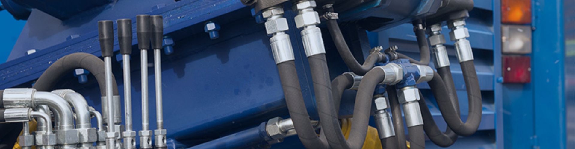
As a hydraulic system designer, you know that selecting the

As a quality manager, you are the gatekeeper of reliability.
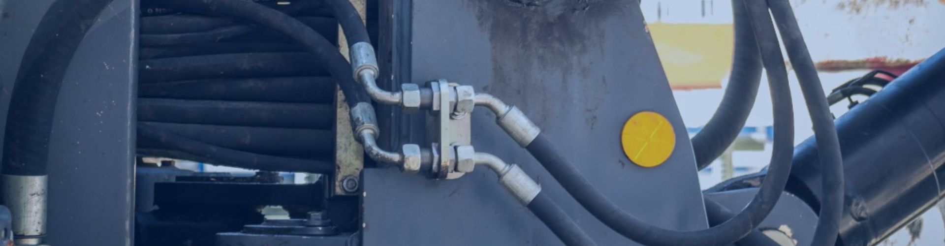
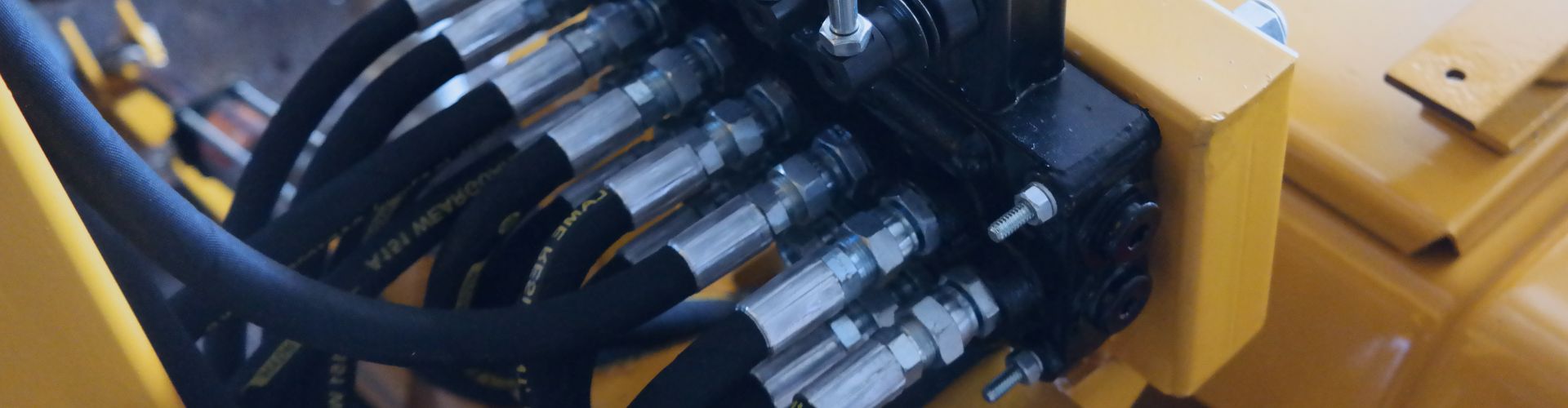
A leaking reusable hydraulic fitting is almost always due to
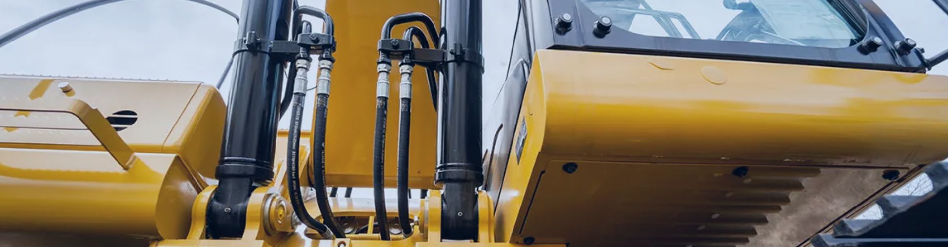
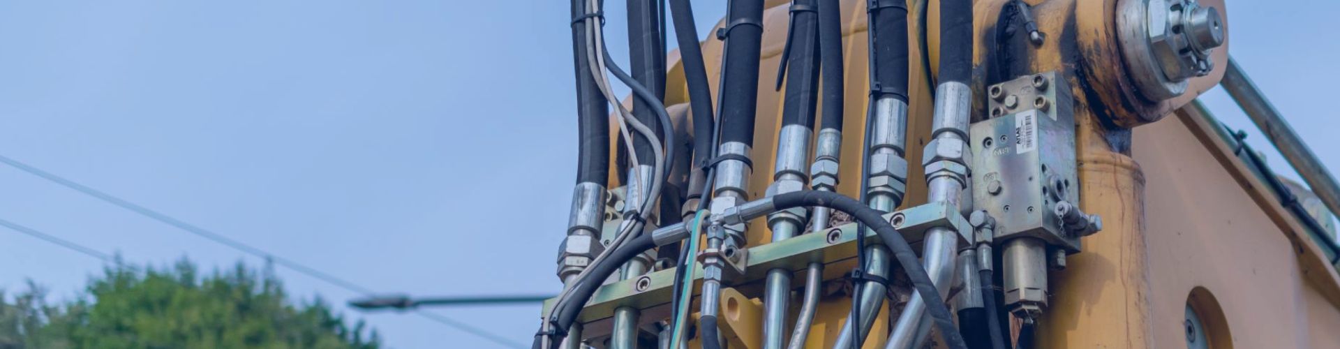
Your equipment vibrates intensely, shaking hydraulic fittings loose. This constant
Your new hydraulic fittings are dimensionally perfect and torqued to
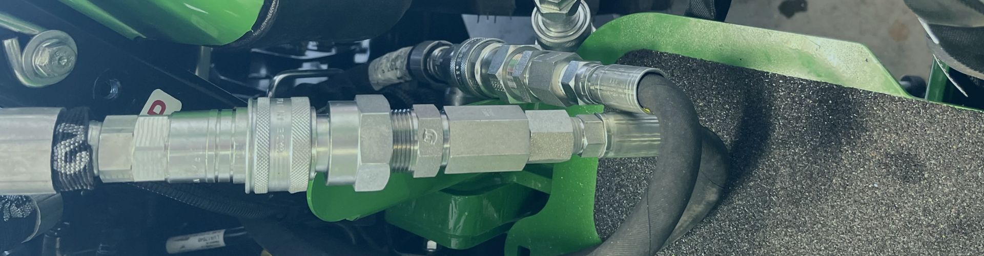
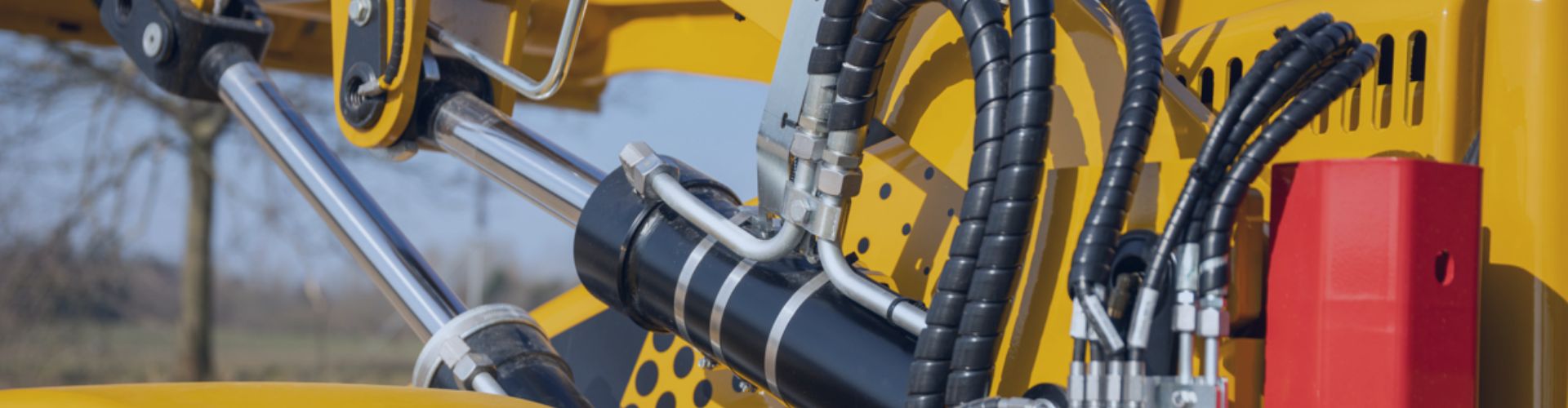
You need to connect hydraulic lines, but making the wrong
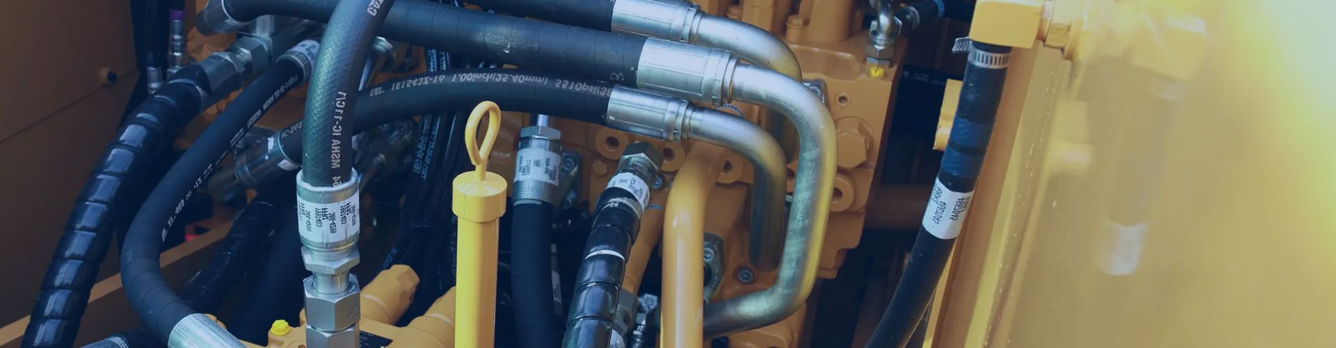
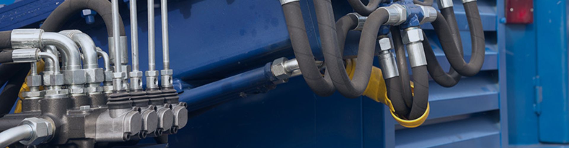
Your hydraulic system is failing, causing leaks or even shattered
Dealing with hydraulic maintenance on American equipment and getting frustrated
Your machine just blew a hydraulic line, miles from the