
How to Select Hydraulic Fittings in 5 Simple Steps?
Are you an engineer struggling with hydraulic system leaks or
Are you an engineer struggling with hydraulic system leaks or
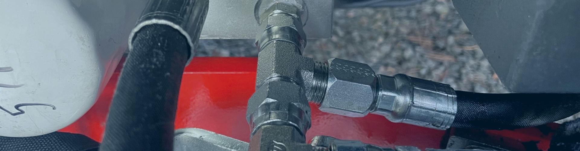
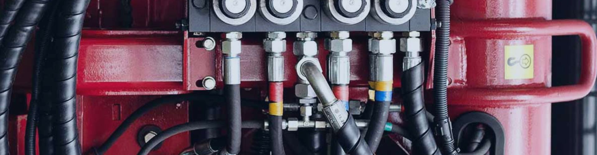
Hydraulic hoses are vital for transferring fluid under pressure. Two

Are you experiencing frustrating leaks or unexpected rust on your
Is your “rust-proof” stainless steel hydraulic fitting showing signs of
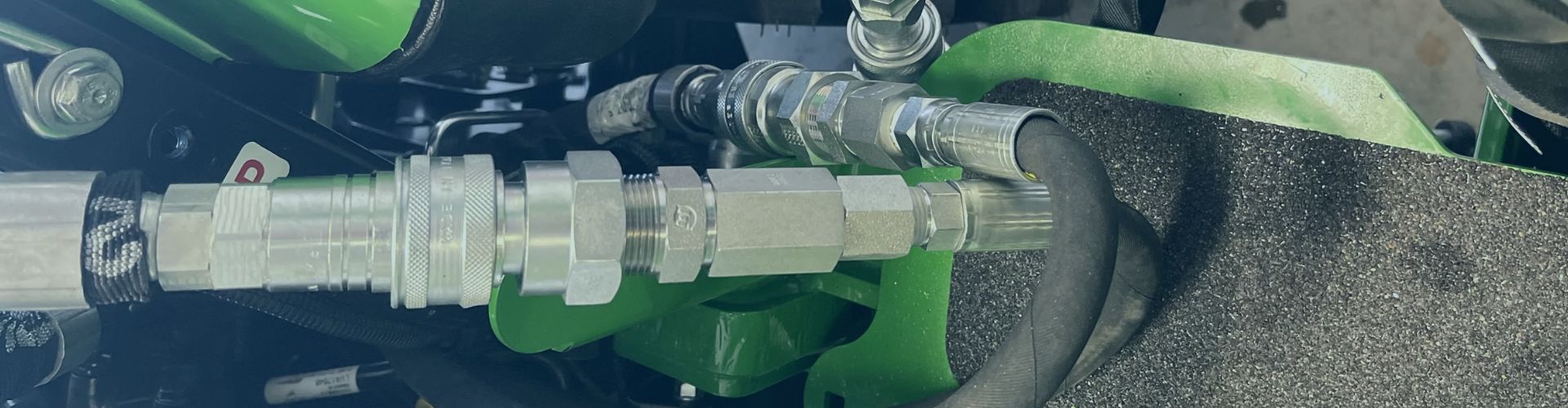
Hydraulic quick couplers allow fast, leak-free hose connections in demanding

You just spent an hour in the field replacing a
Struggling with fittings that leak, corrode, or fail unexpectedly? Choosing
Struggling with persistent leaks at your hydraulic ports? Choosing the
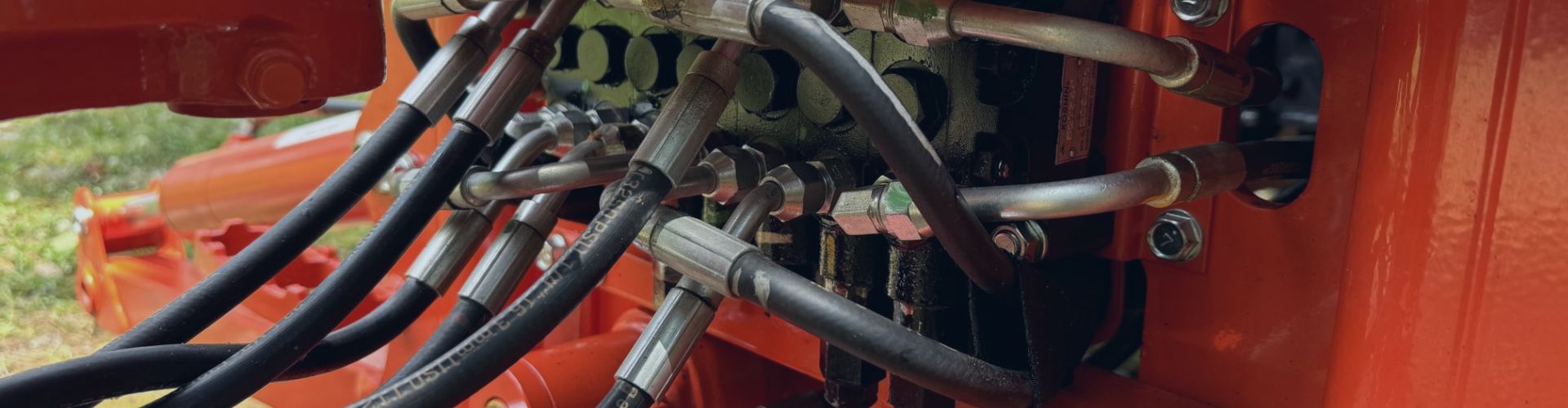
Are your hydraulic hoses failing sooner than they should? A
The science behind reusable hydraulic fittings lies in mechanical engineering,