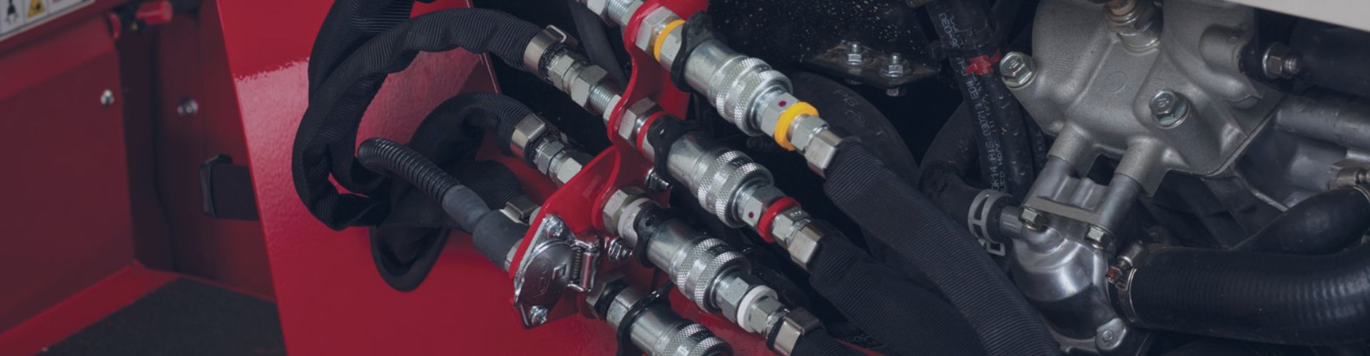
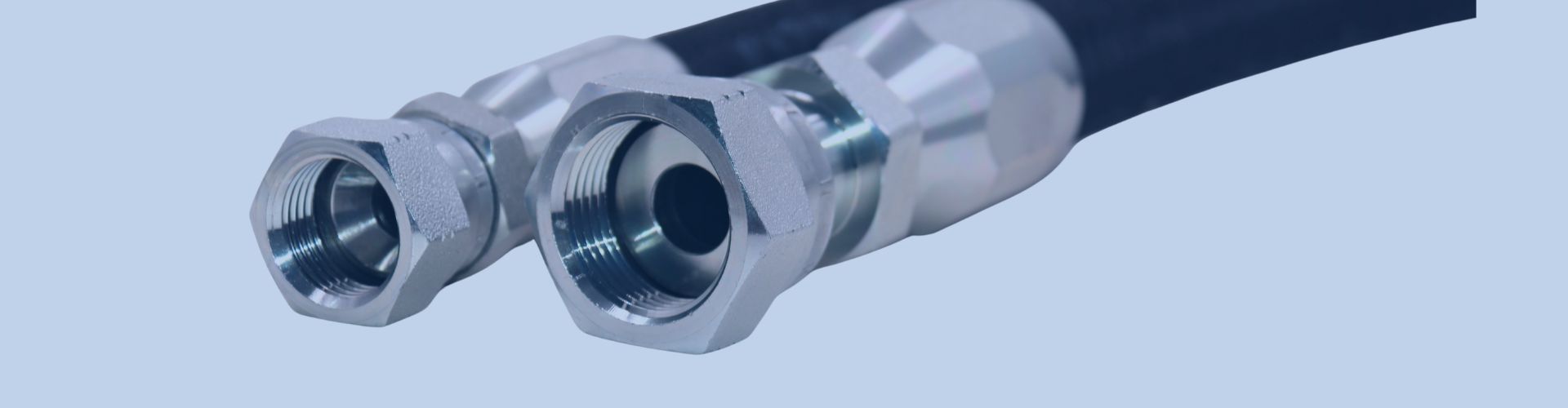
How Tight Should You Torque a Quick Coupler?
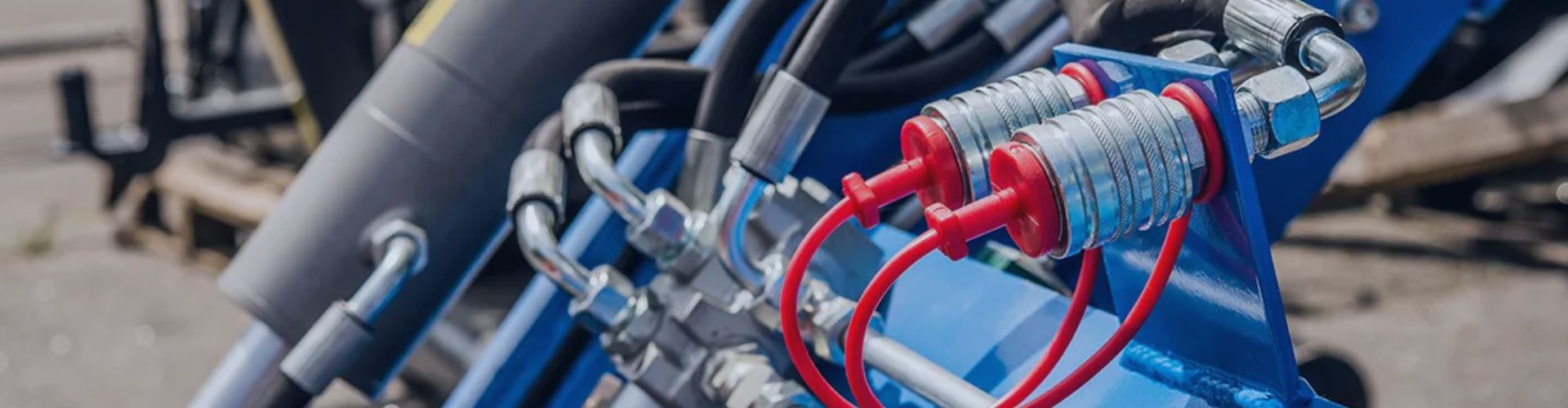
Are you tired of quick couplers that weep or leak
Are you tired of quick couplers that weep or leak

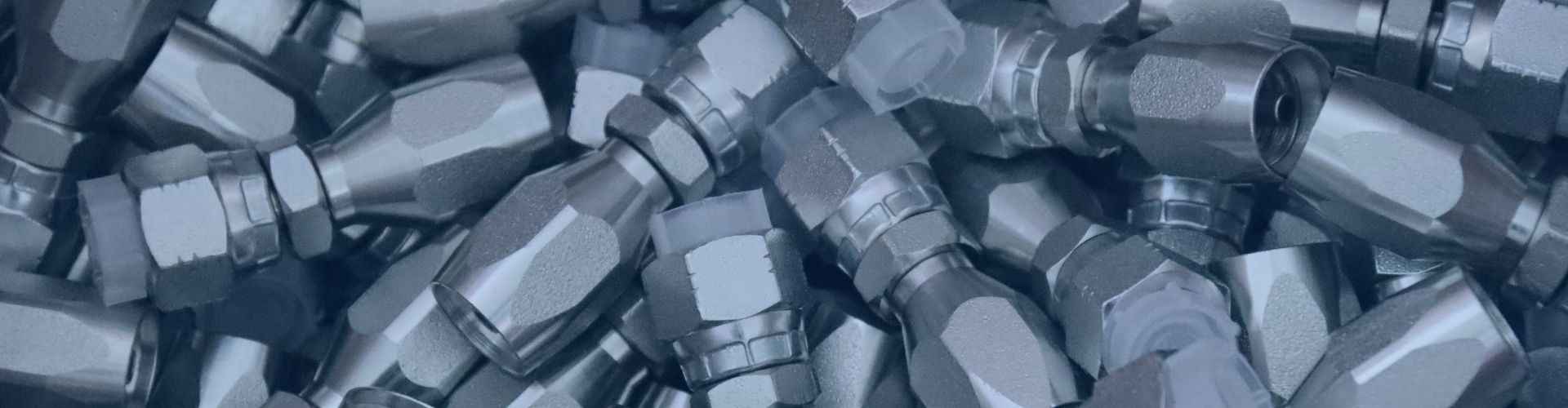
Are you torn between the flexibility of field repairs and
Tired of messy hydraulic fluid spills or connection failures? Choosing
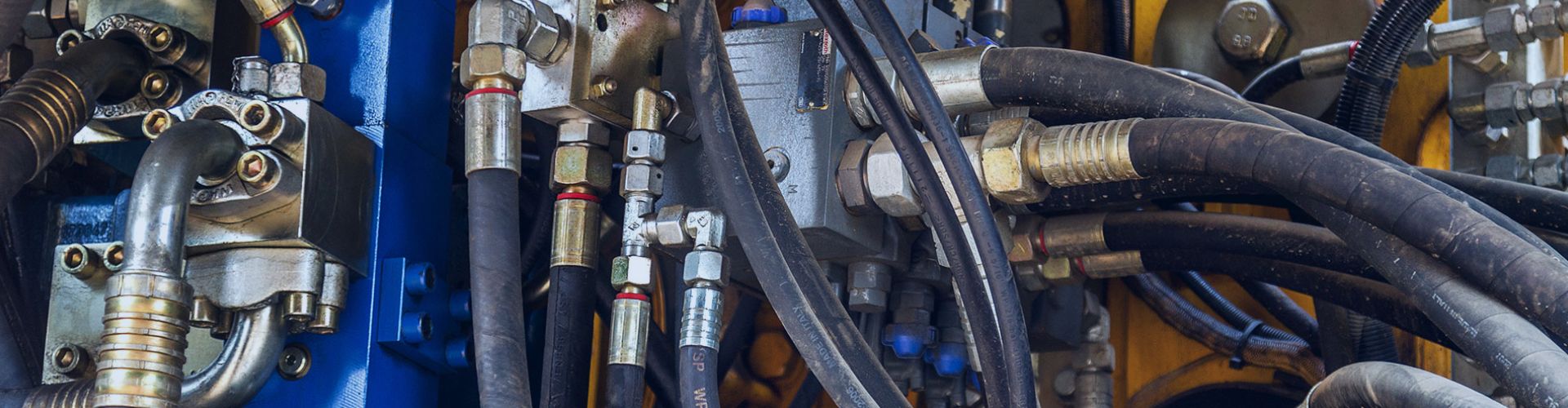
Are your hydraulic systems facing frequent downtime due to hose

In October 2025, the U.S. government imposed 100% tariffs on
Are you tired of dealing with persistent hydraulic leaks, but

Leaks and premature failures in piping systems don’t just interrupt

Is your hydraulic system experiencing premature component wear, sluggish performance,
Struggling with hydraulic leaks and costly downtime? Field repairs can

A single, faulty hydraulic fitting can bring a multi-ton machine