The Complete Hydraulic Hose Manufacturing Process Explained banner

The Complete Hydraulic Hose Manufacturing Process Explained

The hydraulic hose manufacturing process involves a series of precise steps, including material selection, reinforcement, vulcanization, and testing, to ensure the hoses are durable, reliable, and capable of withstanding extreme pressure. Each stage in the process plays a pivotal role in the final product’s performance, making the quality of hydraulic hoses crucial for the safe and efficient operation of hydraulic systems.

Step 1: Sourcing Raw Materials for Hydraulic Hose Production

Types of Materials Used in Hydraulic Hoses (Rubber, PVC, Stainless Steel, etc.)

The foundation of any hydraulic hose lies in the materials used to construct it. Hydraulic hoses are typically made from a combination of synthetic rubber, PVC (polyvinyl chloride), stainless steel, and other specialized compounds. Each material serves a specific purpose in the hose’s overall structure and performance:

Rubber: The most commonly used material for the inner tube and outer cover. Rubber offers excellent flexibility, resistance to abrasion, and the ability to withstand varying temperatures and pressures. Synthetic rubbers like nitrile, EPDM (ethylene propylene diene monomer), and neoprene are commonly used for hydraulic hoses due to their resistance to oil, chemicals, and ozone.

PVC (Polyvinyl Chloride): Often used in lightweight or non-high-pressure applications, PVC is cost-effective and resistant to chemical corrosion. However, it has a lower flexibility and pressure tolerance compared to rubber-based hoses.

Stainless Steel: Used for the reinforcement of hoses, stainless steel wire braids or spirals enhance the strength and pressure resistance of the hose. Stainless steel is preferred for its durability, corrosion resistance, and ability to withstand high-pressure environments, especially in more demanding hydraulic systems.

Other Materials: In some specialized hoses, materials such as polyurethane, polyester, or fluoropolymer coatings may be used for added resistance to abrasion, high temperatures, or chemical exposure.

Hydraulic hose components design Topa

How Material Selection Impacts Hose Durability and Performance

The choice of materials significantly influences the durability, flexibility, and performance of hydraulic hoses. Several factors determine the selection of materials, including:

Pressure Rating: Hydraulic hoses must withstand high pressures without bursting or losing structural integrity. Reinforcing materials like stainless steel wire braid are crucial for enhancing pressure resistance, ensuring the hose can handle the demands of heavy machinery and equipment.

Flexibility and Bend Radius: Hydraulic hoses often need to navigate tight spaces and perform in dynamic systems where the hose is subject to frequent movement. Rubber-based hoses are often preferred for their flexibility, allowing them to bend without kinking or restricting fluid flow.

Chemical and Environmental Resistance: In industrial environments, hoses can be exposed to oils, solvents, UV rays, ozone, and extreme temperatures. The material’s resistance to these elements is essential for maintaining the hose’s performance and longevity. For instance, nitrile rubber hoses are often used in systems exposed to petroleum-based fluids, while EPDM hoses are preferred in environments with exposure to ozone and UV light.

Abrasion Resistance: For hoses exposed to rough surfaces or high-wear areas, materials with excellent abrasion resistance, such as polyurethane or rubber covers, are vital. This prevents the hose from wearing out prematurely and ensures that it can withstand harsh environments without compromising its functionality.

Step 2: Creating the Inner Tube – The Core of the Hydraulic Hose

The Extrusion Process for Forming the Inner Tube

The inner tube is the most critical component of a hydraulic hose, as it is responsible for carrying the pressurized fluid. The process of creating the inner tube begins with extrusion, a method that involves forcing heated rubber or synthetic materials through a mold or die to form a continuous tube shape. The extrusion process ensures that the inner tube has a smooth and consistent surface, which is essential for maintaining fluid flow without obstruction or turbulence.

Material Heating and Melting: The rubber compound is first heated to a molten state, making it soft enough to flow through the extrusion die.

Extrusion Through a Die: The molten rubber is then pushed through a specifically shaped die, which forms the tube to the required diameter and thickness. This step is critical to ensuring the correct wall thickness and smoothness of the inner tube, which directly affects its ability to withstand pressure and resist wear.

Cooling and Setting: Once the rubber has been extruded through the die, it is cooled using a water bath or air cooling system, solidifying the shape of the tube.

The extrusion process allows manufacturers to produce inner tubes with precise dimensions, ensuring uniformity and consistency across every hose produced.

Types of Rubber Compounds Used for Inner Tubes

The type of rubber compound used in the inner tube plays a vital role in the hose’s ability to resist pressure, abrasion, and chemical degradation. The most common types of rubber compounds used for hydraulic hose inner tubes include:

Nitrile Rubber (NBR): Nitrile rubber is widely used for hydraulic hoses, especially in applications involving petroleum-based fluids and oils. NBR is known for its excellent oil resistance and durability under high-pressure conditions. It is ideal for hydraulic systems in industries like automotive and machinery, where petroleum-based fluids are common.

EPDM Rubber (Ethylene Propylene Diene Monomer): EPDM rubber is resistant to ozone, UV rays, and weathering, making it suitable for hydraulic hoses exposed to outdoor environments. While it is not as oil-resistant as nitrile rubber, it offers excellent resistance to water, steam, and many chemical compounds.

Neoprene Rubber: Neoprene is used for applications that require resistance to oil, fuel, and a wide range of chemicals. It also provides flexibility and durability, making it suitable for hydraulic systems with more demanding fluid types.

Fluoroelastomers (FKM): For extreme chemical resistance, fluoropolymers such as FKM (Viton®) are used. These are ideal for high-temperature applications where the fluid may contain aggressive chemicals, acids, or high-temperature oils.

The choice of rubber compound depends on the type of fluid being conveyed, the temperature range, and the environmental conditions the hose will be exposed to.

Step 3: Reinforcement – Strengthening the Hose for High Pressure

Different Types of Reinforcement Materials (Steel Wire, Braiding, Spiraling)

Reinforcement is a critical part of the hydraulic hose manufacturing process. It adds the strength and durability necessary to handle high-pressure conditions, while also preventing the hose from expanding or bursting under pressure. There are several types of reinforcement materials used to achieve this:

Steel Wire: The most common reinforcement material used in hydraulic hoses is steel wire, which provides excellent tensile strength. Steel wire is ideal for high-pressure applications and is resistant to wear and abrasion. The wire is typically formed into braids or spirals to increase the hose’s resistance to pressure.

Braiding: In braided reinforcement, multiple steel wires are woven together in a criss-cross pattern to form a layer that strengthens the hose. The braiding method is ideal for hoses that need flexibility as well as high pressure resistance. Braided reinforcement helps distribute pressure evenly along the hose, preventing localized weak points that could cause ruptures.

Spiraling: Spiral reinforcement involves winding steel wires around the inner tube in a helical or spiral pattern. Spiral reinforcement provides higher resistance to higher pressures and is often used in hoses exposed to severe or dynamic conditions. It is more rigid than braided reinforcement but offers superior pressure resistance, especially in applications where the hose must withstand pulses or fluctuations in pressure.

Hybrid Reinforcement: Some hydraulic hoses use a combination of braided and spiral reinforcement layers. This hybrid approach combines the flexibility of braiding with the strength of spiraling, providing both durability and the ability to withstand extreme pressure.

Hydraulic hose braid factory

The Process of Braiding and Spiraling Reinforcement Wires

The process of reinforcing the hydraulic hose with steel wire involves two main methods: braiding and spiraling.

Braiding Process:

In the braiding process, multiple steel wires are woven together using high-speed machines. The wire is arranged in a pattern where it crisscrosses over and under each other, creating a strong and flexible layer. This method allows the hose to bend more easily while maintaining high tensile strength.

During the braiding, machines automatically move the wires in a way that ensures the proper tension and coverage, providing uniform reinforcement across the entire length of the hose. The braided layer is applied over the inner tube after it has been formed, and the number of braids (e.g., single or double braid) will affect the overall strength of the hose.

Spiraling Process:

In the spiraling process, steel wire is wound around the hose in a continuous spiral, forming multiple layers of reinforcement. The wire is wound at a precise angle to ensure maximum strength and pressure resistance.

Typically, the spiral layer is applied in stages, with additional layers of wire added for extra strength. The spiral reinforcement provides more rigid support for the hose, particularly in high-pressure applications or hoses subjected to external abrasion or pressure spikes.

Spiral reinforcement is often used for hoses that require heavy-duty applications, such as those in oil and gas drilling, mining, and other high-pressure environments.

Step 4: Adding the Outer Cover

Types of Outer Cover Materials (Rubber, PVC, Thermoplastic)

The outer cover of a hydraulic hose plays a crucial role in protecting the hose from environmental factors such as abrasion, UV radiation, chemical exposure, and extreme temperatures. It acts as the first line of defense against damage from external sources, ensuring that the inner layers (tube and reinforcement) remain intact and function properly. There are several materials commonly used for the outer cover of hydraulic hoses, each offering specific benefits based on the application:

Rubber: Rubber is the most widely used material for hydraulic hose covers due to its excellent abrasion resistance, flexibility, and ability to withstand a variety of harsh environments. It is often chosen for its resilience to heat, ozone, UV exposure, and chemicals. Synthetic rubbers such as EPDM (ethylene propylene diene monomer) and NBR (nitrile rubber) are commonly used for the outer cover, providing additional resistance to oils, fuels, and chemicals.

PVC (Polyvinyl Chloride): PVC is a more cost-effective material used in hydraulic hoses where abrasion resistance is less critical. It offers basic protection from environmental elements like moisture and some chemicals, though it has lower resistance to high temperatures and pressure than rubber. PVC-covered hoses are typically used in lighter-duty or low-pressure applications.

Thermoplastic: Thermoplastic materials, such as polyurethane and nylon, are also used for hydraulic hose covers, especially in situations requiring extreme flexibility and lightweight hoses. Thermoplastic hoses provide excellent resistance to abrasion, oils, and ozone, making them ideal for demanding environments. These materials are often used in applications where hoses must bend easily or be exposed to fluctuating temperatures.

Thermoplastic Elastomer (TPE): TPE combines the properties of rubber and plastic, offering flexibility, weather resistance, and enhanced abrasion protection. TPE-covered hoses are commonly used in food processing, pharmaceutical, and industrial applications where high levels of cleanliness and flexibility are necessary.

The Process of Extruding the Outer Cover

The process of adding the outer cover to the hydraulic hose involves extrusion, a manufacturing method that shapes the material into a continuous cover over the reinforced hose core. The extrusion process ensures that the outer cover adheres securely to reinforcement and provides uniform protection against environmental hazards.

Material Selection and Preparation: The chosen material (rubber, PVC, or thermoplastic) is prepared by mixing it with specific additives that enhance its performance. For example, UV stabilizers, anti-aging agents, and anti-abrasion compounds may be added to improve the longevity and durability of the cover.

Extrusion Process:

The raw material is heated and softened, typically in an extrusion machine where it is forced through a die that shapes it into the desired form. The extruder applies pressure to push the material around the braided or spiraled reinforcement, ensuring the cover bonds securely to the underlying layers.

The extruder is designed to maintain consistent pressure and temperature, which is crucial for achieving an even and smooth outer layer. The material is shaped into a continuous tube that fits snugly over the hose’s reinforcement layer.

Cooling and Setting: After the outer cover is extruded, it is rapidly cooled to set the shape and ensure it retains its structure. This cooling phase helps solidify the material and allows it to harden, creating a protective barrier around the hose.

Cutting to Length: Once the extruded outer cover has cooled and solidified, the hose is cut to the required lengths. This ensures that the finished hose is ready for assembly or further processing, such as fitting installation.

Step 5: Vulcanization – The Secret to Durability and Flexibility

What is Vulcanization and Why It’s Essential for Hose Quality

Vulcanization is a critical process in the manufacturing of hydraulic hoses, where heat and pressure are applied to the rubber compounds used in the hose. This process chemically bonds the rubber molecules, improving the material’s strength, durability, and flexibility. Essentially, vulcanization transforms raw rubber into a more stable and versatile material that can withstand the demanding conditions of hydraulic systems.

Vulcanization involves the addition of sulfur or other cross-linking agents to the rubber compound, which creates cross-links between the polymer chains. This curing process results in the rubber becoming harder, more heat-resistant, and more resistant to abrasion, chemicals, and other environmental factors. For hydraulic hoses, this means the hose will last longer, resist damage from friction, and perform reliably under high-pressure conditions.

How Heat and Pressure Create Durable, Flexible Hoses

The vulcanization process is achieved through a combination of heat and pressure, which together cause the rubber molecules to bond in a way that enhances the material’s properties. Here’s how the process works:

Preparation of Rubber Compound:

Before vulcanization, the rubber material is mixed with other chemicals, such as sulfur, accelerators, and activators, to create the right balance of hardness, flexibility, and durability. This compound is then ready to undergo the curing process.

Vulcanization Chamber:

The rubber compound, along with the reinforced hose (inner tube, braiding, and outer cover), is placed into a vulcanizing chamber (also known as an autoclave or curing oven). In this chamber, the hose is exposed to high temperatures (usually between 160-200°C or 320-390°F) and pressure for a specified period.

Cross-Linking:

The combination of heat and pressure initiates a chemical reaction in the rubber, causing the polymer chains to link together, creating a more complex network structure. This cross-linking process is what gives the rubber its enhanced durability, flexibility, and resistance to wear.

The cross-links formed during vulcanization are what make the rubber more stable, preventing it from deteriorating under high pressure, extreme temperatures, or exposure to chemicals.

Cooling and Setting:

Once the vulcanization process is complete, the hose is cooled gradually to allow the rubber to harden and set into its final shape. The cooling process solidifies the chemical bonds created during vulcanization, ensuring that the hose retains its new properties.

Final Inspection and Quality Control – Ensuring Each Hose is Ready for Use

Detailed Inspection Process to Check for Defects or Inconsistencies

The final inspection and quality control phase is one of the most critical steps in the hydraulic hose manufacturing process. This stage ensures that each hose meets the required performance standards and is free from defects or inconsistencies that could compromise its safety and functionality. During this process, a variety of visual, mechanical, and dimensional checks are performed:

Visual Inspection:

The hoses are carefully inspected for surface defects such as cracks, cuts, blisters, or any foreign contaminants embedded in the material. Any imperfections in the outer cover or reinforcement can affect the performance of the hose, especially under high pressure.

Dimensional Checks:

The hose’s length, diameter, and wall thickness are measured to ensure they conform to the specified tolerances. Even small variations in size can lead to improper fitment or reduce the hose’s pressure tolerance.

    Pressure Testing:

    Each hose undergoes pressure testing to verify that it can handle the specified operating pressure without any signs of failure. This is usually done by pressurizing the hose to a higher level than its rated working pressure to check for any leakage, bulging, or ruptures.

      Abrasion and Environmental Testing:

      Some hoses undergo abrasion tests or environmental stress testing to simulate real-world conditions. This could involve bending, flexing, or exposure to UV light or extreme temperatures. These tests ensure that the hose will maintain its integrity in the environments it will be used in.

        Leakage Tests:

        Leak detection is done by using air or fluid to check for leaks along the hose assembly. This test ensures that the hose is completely sealed and will not leak under normal working conditions.

          Reinforcement Inspection:

          The reinforcement layers (braided or spiral steel wires) are also checked for uniformity and strength. Any inconsistencies in the reinforcement can affect the hose’s pressure tolerance and flexibility.

          brust Test Topa Factory

            How Each Hose Undergoes Final Checks Before Leaving the Factory

            Once the individual inspection steps are completed, the hose is subject to a final round of checks before being approved for shipment or installation:

            Marking and Labeling:

            Each hose is marked with key information such as part number, pressure rating, manufacturing date, and batch number. This ensures that each hose can be traced back to its production lot in case of any future quality concerns.

              Final Assembly:

              If applicable, the hydraulic hose will undergo final assembly, which involves attaching the necessary fittings or connectors. These fittings are also inspected to ensure they are securely attached and correctly aligned with the hose ends.

                Documentation Review:

                The production records are reviewed to confirm that all materials, specifications, and manufacturing steps meet the required standards. This includes reviewing test results from earlier stages of the manufacturing process, ensuring that all tests were passed.

                  End-of-Line Inspection:

                   An experienced quality control technician performs a final visual check of the hose to ensure that it is free from defects. If everything meets the criteria, the hose is approved for shipment.

                    Customization – Tailoring Hydraulic Hoses to Specific Needs

                    Custom Lengths, Diameters, and Pressure Ratings

                    Customization is an essential service for clients who require hydraulic hoses to meet the specific demands of their operations. Every hydraulic system is unique, with varying needs based on the machinery, environment, and fluids being handled. Customization allows manufacturers to tailor hoses precisely to those requirements.

                    Custom Lengths: Clients may require hoses in specific lengths to fit the exact measurements of their hydraulic systems. Whether a hose needs to connect distant components, or it must fit into a compact space, custom lengths ensure that there is no excess hose, reducing clutter and preventing safety risks associated with slack or coiled hoses.

                    Custom Diameters: Hydraulic hoses come in a range of inner and outer diameters to accommodate different fluid flow rates and pressure requirements. Custom diameters ensure that the hose fits perfectly into connectors and ports, minimizing the risk of leaks, pressure loss, or system inefficiency. Whether the system requires a small-diameter hose for precision control or a larger hose for high-volume applications, tailored sizing ensures optimal flow.

                    Custom Pressure Ratings: Not all hydraulic systems operate at the same pressures. Some systems require hoses rated for very high pressure (up to 10,000 psi or more), while others may only need hoses rated for low-pressure conditions. Custom pressure ratings allow clients to choose hoses that can safely handle the pressures of their specific applications without unnecessary over-specification, which can lead to higher costs.

                    Custom Labeling, Printing, and Packaging Options

                    In addition to functional customization, many clients also require branding and aesthetic customization for their hydraulic hoses, especially for retail, distribution, or specialized equipment. Custom labeling and packaging help reinforce brand identity, improve product traceability, and enhance the presentation of the final product.

                    Custom Labeling: Custom labels allow manufacturers to provide key product details, such as part numbers, pressure ratings, manufacturing dates, and safety warnings, directly on the hose. This ensures that users can easily identify the hose’s specifications and understand its intended application. It also helps with maintenance schedules, as hoses can be traced back to their production batch for any quality checks.

                    Custom Printing: Some clients may want specific logos, company names, or other marketing messages printed directly onto the hose or its cover. This not only promotes brand visibility but can also make it easier to identify hoses in a complex system, improving maintenance efficiency. Custom printing may also include barcodes or QR codes for easy digital access to product specifications and usage guidelines.

                    Custom Packaging: Packaging plays an important role in protecting the hydraulic hose during shipping and storage. Customized packaging options, such as specific reel sizes or protective wraps, ensure the hoses are stored safely and are presented in a way that is convenient for end-users. Packaging customization can also help with reducing packaging waste, optimizing storage, and facilitating easier handling.

                    Conclusion

                    To ensure the highest quality, it’s essential to choose a reliable manufacturer that prioritizes expertise, quality control, customization capabilities, and customer support. If you have any needs, you can contact Topa and we will provide you with the highest quality hydraulic hose products.


                    FAQ

                    What materials are used in hydraulic hose manufacturing?

                    Hydraulic hoses are made from materials like rubber, PVC, stainless steel, and thermoplastics, each chosen for its specific properties such as flexibility, durability, and pressure resistance.

                    How is the inner tube of a hydraulic hose made?

                    The inner tube is formed through an extrusion process, where rubber compounds are shaped to provide fluid containment and pressure resistance, ensuring optimal performance.

                    What is the purpose of reinforcement in hydraulic hoses?

                    Reinforcement, typically made of braided or spiraled steel wire, adds strength to the hose, enabling it to withstand high-pressure environments without failure.

                    Why is vulcanization important in hydraulic hose manufacturing?

                    Vulcanization is a process that bonds rubber molecules together, increasing the hose’s strength, flexibility, and heat resistance, essential for long-lasting performance.

                    Can hydraulic hoses be customized for specific needs?

                    Yes, hydraulic hoses can be customized in terms of length, diameter, pressure rating, and even labeling or packaging to meet the unique requirements of different industries.

                    What are the key factors when choosing a hydraulic hose manufacturer?

                    When selecting a manufacturer, consider factors like expertise, quality control processes, customization capabilities, and reliable customer support to ensure high-quality products.

                    Hydraulic Hose Quality Test banner

                    Hydraulic Hose Quality Test: What You Need to Look for

                    The quality of the hose directly impacts the hydraulic system’s performance—subpar hoses can reduce pressure capacity, cause leaks, or even result in system failure, leading to costly downtime and safety risks. Routine inspections not only prolong hose life but also enhance system reliability, reduce maintenance costs, and mitigate potential safety hazards, helping businesses avoid unexpected repairs and ensuring smooth operations.

                    Key Factors Affecting Hydraulic Hose Quality

                    The overall performance and longevity of a hydraulic hose are determined by several critical factors. Understanding these key elements can help ensure that your hoses perform at their best, even under extreme conditions.

                    Hose Material and Construction Quality

                    The material used in the construction of a hydraulic hose plays a major role in its durability and effectiveness. High-quality materials like synthetic rubber, thermoplastics, and braided steel offer superior resistance to abrasion, pressure, and chemical exposure. The construction process also affects hose strength; multi-layered hoses with braided or spiral reinforcements offer better performance compared to single-layer hoses. Selecting the right materials is crucial for ensuring that the hose can withstand both internal and external stress.

                    The Importance of Hose Reinforcement

                    Reinforcement is one of the key features that define a hydraulic hose’s ability to handle high pressure. Reinforced hoses use layers of steel wire or other materials to provide additional strength and flexibility. This reinforcement helps prevent hose failure under pressure and ensures a longer lifespan. Without proper reinforcement, hoses are more prone to kinks, collapses, and even bursts, especially when exposed to high-stress conditions.

                    How Environmental Factors Impact Hose Durability

                    Environmental conditions like temperature, exposure to UV rays, moisture, chemicals, and physical wear can significantly impact the performance and lifespan of a hydraulic hose. For example, high temperatures can cause hose materials to degrade, while exposure to harsh chemicals can weaken the hose structure. Additionally, frequent movement or friction against rough surfaces can lead to abrasion, compromising the hose’s durability. Regular testing and material selection based on environmental factors help minimize these risks, ensuring that hoses continue to perform efficiently in challenging environments.

                    Pressure Testing

                    Pressure testing is one of the most fundamental and crucial tests conducted on hydraulic hoses to ensure their safety and functionality. This test simulates the operational conditions a hose will face during use, verifying that it can withstand the pressure required for the system to function correctly. It helps detect weak points in the hose that may otherwise lead to leaks or bursts under pressure, preventing potential catastrophic failures.

                    What is Hose Pressure Testing?

                    Hose pressure testing involves subjecting the hydraulic hose to a specific pressure level, often higher than its normal operating pressure, to evaluate its strength and integrity. The test checks whether the hose can handle high-pressure conditions without leaking or failing. The pressure is applied gradually, and the hose is monitored for any signs of weakness, such as bulging, swelling, or leaking, which can indicate poor material quality or a defective hose.

                    Steps Involved in the Pressure Testing Procedure

                    The pressure testing procedure generally follows these steps:

                    Preparation: The hose is securely attached to a testing rig, and all fittings, adapters, and connectors are checked for compatibility. The hose is filled with fluid, typically water or air, to avoid potential risk from the hydraulic fluid during testing.

                    Pressurization: The pressure is gradually increased to a specified value, usually 1.5 to 2 times the hose’s rated working pressure. The system is slowly pressurized to avoid shock loading on the hose.

                    Monitoring: The hose is carefully inspected during the pressurization process. Any visible damage, leaks, or deformation is recorded. Pressure gauges are used to ensure accurate measurement of the applied pressure.

                    Assessment: After the test, the hose is depressurized, and further inspection is conducted to assess its condition. If the hose passes without visible damage or leakage, it is deemed suitable for use. If any issues arise, the hose is either repaired or replaced.

                    Recommended Pressure Limits for Different Hose Types

                    Different types of hoses are designed to handle varying levels of pressure. For instance, low-pressure hoses are typically rated for pressures up to 300 PSI, while high-pressure hoses can handle pressures well over 10,000 PSI, depending on their construction and reinforcement. It’s critical to match the pressure testing levels to the hose’s intended application and industry standards.

                    Testing hoses beyond their rated capacity helps ensure that they are capable of handling unexpected pressure spikes without failure, providing extra assurance that they will perform safely in real-world conditions.

                    Burst Pressure Testing

                    Burst pressure testing is one of the most critical tests performed on hydraulic hoses to determine their maximum strength and ability to withstand extreme pressure conditions. This test ensures that the hose can handle unexpected pressure spikes that may occur during operation, preventing catastrophic failures that could damage equipment or compromise safety.

                    Hoses Burst Pressure test

                    What is Burst Pressure Testing?

                    Burst pressure testing involves subjecting the hydraulic hose to a pressure level significantly higher than its maximum rated operating pressure. The goal is to determine the hose’s ability to withstand pressure beyond its normal limits without rupturing. This test simulates extreme conditions, such as hydraulic system surges or pressure spikes, to evaluate the hose’s durability and integrity. The hose is gradually pressurized until it bursts, at which point the pressure at which the hose fails is recorded.

                    How Burst Pressure Testing is Performed

                    The burst pressure test is conducted by connecting the hose to a specialized testing rig that can precisely control and measure the applied pressure. Here’s how the test generally unfolds:

                    Preparation: The hose is securely connected to the test rig, ensuring that all fittings and connectors are properly sealed. The hose is filled with fluid, typically water or another non-compressible substance, to reduce the risks associated with high-pressure testing.
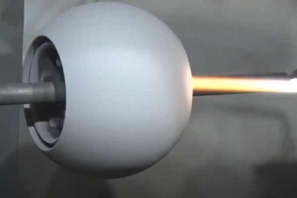
                    Pressure Application: The pressure is gradually increased in controlled increments, starting from the normal working pressure and steadily rising. The hose is carefully monitored for any signs of stress, such as bulging, stretching, or deformation, as the pressure increases.

                    Failure Point Detection: The pressure continues to increase until the hose bursts, and the point at which this occurs is noted. This burst pressure is the maximum pressure the hose can handle before failing. It’s typically 1.5 to 2 times the hose’s rated working pressure, depending on industry standards and hose specifications.

                    Post-Test Analysis: After the test, the hose’s failure is analyzed to determine the exact cause, such as material weakness or improper construction. This analysis helps manufacturers and operators understand the limits of the hose and provides valuable information for future testing or hose selection.

                    Leak Testing

                    Leak testing is a critical process in ensuring the integrity and safety of hydraulic hoses. Even a small leak can lead to significant problems, including system failures, environmental damage, and safety hazards. Leak testing is designed to detect any signs of leakage in the hose, ensuring that it performs reliably under pressure without compromising fluid containment or system functionality.

                    What is Leak Testing?

                    Leak testing involves pressurizing the hydraulic hose with a fluid (usually water, air, or the same hydraulic fluid used in the system) and inspecting it for any signs of leakage. The goal is to ensure that the hose seals properly and that no fluid escapes from the hose, which could result in performance issues, fluid loss, or dangerous conditions in the hydraulic system. By identifying leaks early on, this test helps prevent equipment damage, contamination, and safety risks.

                    Types of Leak Testing Methods

                    There are several methods used for leak testing hydraulic hoses, each with specific advantages depending on the application and the system’s requirements:

                    Pressure Decay Test: In this method, the hose is pressurized to the desired test pressure, and the pressure is monitored over a period of time. If the pressure drops, it indicates that there is a leak. This is one of the most common methods for detecting small leaks, as it is highly sensitive and can identify even the most minor fluid loss.

                    Bubble Test: The bubble test involves applying a soapy solution or a special leak detection fluid over the hose and then pressuring the hose. If there is a leak, bubbles will form at the site of the leak, making it easy to spot. This method is simple and effective for detecting visible leaks, especially in hoses with small holes or cracks.

                    Ultrasonic Leak Detection: This advanced method uses ultrasonic sound waves to detect leaks. Ultrasonic sensors are used to listen for the sound of escaping fluid or air, which can indicate a leak in the hose. This method is highly effective for locating leaks in hard-to-reach areas or for hoses in service, where traditional testing methods may not be feasible.

                    Vacuum Testing: In vacuum leak testing, the hose is placed in a vacuum chamber, and the internal pressure is reduced. Any leaks will cause air to be drawn into the hose, which can be detected and pinpointed. This method is often used for hoses designed to operate under vacuum conditions.

                    Tensile Strength Testing

                    Tensile strength testing is designed to evaluate a hydraulic hose’s ability to resist stretching and breakage under tension. This test measures how much force the hose can withstand before it begins to elongate, deform, or rupture. It is particularly important for hoses that will be exposed to significant mechanical stress, such as during installation or when they are subject to external forces in dynamic systems.

                    What is Tensile Strength Testing?

                    Tensile strength testing involves applying a pulling force to the hydraulic hose to determine how much stress it can handle before stretching or breaking. The test is conducted by attaching each end of the hose to a fixture that applies a controlled, gradual pulling force. The force is steadily increased until the hose either deforms or reaches its breaking point. The maximum force the hose can endure before failure is recorded as its tensile strength.

                    How Tensile Strength Testing is Performed

                    Tensile strength testing is typically performed in a lab setting using a universal testing machine or a dedicated tensile tester. Here’s an outline of the steps involved in the procedure:

                    Preparation: The hydraulic hose is securely mounted between two grips on the testing machine. The hose should be free of any bends or damage, and all fittings should be checked for proper installation.

                    Force Application: A gradual, controlled pulling force is applied to the hose. The machine measures the force at each increment and records the elongation of the hose as tension is applied.

                    Observation: The hose is monitored for any signs of stretching, deformation, or failure. If the hose begins to show any abnormal elongation, bulging, or if it breaks, the force at which these issues occur is noted.

                    Results: The tensile strength is determined by the amount of force the hose can withstand before it either stretches significantly or ruptures. The results help engineers assess the hose’s suitability for specific applications where tensile stress is a concern.

                    Abrasion Resistance Testing

                    Abrasion resistance testing is essential for assessing how well a hydraulic hose can withstand the wear and tear caused by friction, rough surfaces, and abrasive environments. Since hydraulic hoses often operate in conditions where they come into direct contact with sharp edges, moving parts, or rough materials, it is vital to ensure that they are durable enough to endure these harsh conditions without premature degradation or failure.

                    What is Abrasion Resistance Testing?

                    Abrasion resistance testing evaluates a hose’s ability to resist surface wear when subjected to friction, rubbing, and physical contact with external surfaces. The test simulates the typical conditions that the hose might encounter during operation, such as exposure to abrasive surfaces, sand, gravel, or rough machinery parts. The objective is to identify whether the hose material can maintain its integrity and performance over time, even in environments where abrasion is a constant factor.

                    How Abrasion Resistance Testing is Performed

                    Abrasion resistance testing is typically done using specialized equipment that simulates real-world conditions of wear. The most common methods include:

                    Taber Abrasion Test: In this method, the hose is subjected to continuous rubbing or scraping against an abrasive surface (often a rotating wheel or disk) under a controlled weight. The amount of material lost from the hose surface is measured after a set number of rotations or time, giving an indication of how resistant the hose is to abrasion.

                    Rotary Drum Abrasion Test: This test involves placing the hose inside a rotating drum filled with abrasive particles like sand or grit. The hose is subjected to prolonged exposure to these particles as the drum rotates, simulating wear caused by friction and contact with rough materials. The weight loss or changes in surface appearance after the test indicate the hose’s wear resistance.

                    Scratch Test: In the scratch test, a controlled scratch is made on the surface of the hose with a sharp, abrasive object. The depth and extent of the scratch provide a clear indication of the hose’s surface hardness and its ability to resist surface damage.

                    Fatigue Testing

                    Fatigue testing is essential for evaluating how well a hydraulic hose can withstand repeated cycles of stress and strain without failing. Hydraulic systems often experience fluctuations in pressure and mechanical forces during operation, and these repetitive stresses can cause materials to weaken over time. Fatigue testing simulates these conditions, helping to determine the hose’s long-term durability and ability to endure cyclic loading without cracking, rupturing, or losing performance.

                    What is Fatigue Testing?

                    Fatigue testing involves subjecting a hydraulic hose to repeated cycles of pressure and movement to simulate real-world stress over extended periods. This test aims to assess the hose’s resistance to failure under conditions where the load and pressure fluctuate, such as in dynamic systems where hoses experience constant bending, stretching, or compression. The goal is to determine how many cycles the hose can endure before showing signs of degradation or failure, such as cracking, leaks, or bulging.

                    How Fatigue Testing is Performed

                    Fatigue testing is typically done using specialized testing rigs that apply repeated cyclic pressure or mechanical stress to the hose. The testing procedure generally involves the following steps:

                    Preparation: The hydraulic hose is securely attached to the test rig, and the system is configured to apply a repeated load or pressure cycle. The hose is filled with the appropriate test fluid, and all connections are checked to ensure they are properly sealed.

                    Cyclic Loading: The hose is subjected to a specific pressure range or mechanical movement (such as bending or stretching) over a set period. This cycling simulates the repetitive forces the hose would experience in actual service.

                    Monitoring: During the test, the hose is monitored for any signs of stress or damage, such as cracks, leaks, or bulging. The number of cycles is carefully counted, and the hose’s performance is evaluated after each cycle or at predetermined intervals.

                    Failure Point Detection: The hose is tested until it shows clear signs of failure, such as rupture or significant performance degradation. The results are analyzed to determine the hose’s overall fatigue life and how it compares to industry standards.

                    Impulse Testing

                    Impulse testing is a critical test used to simulate the effects of cyclical pressure fluctuations that hydraulic hoses experience during operation. These fluctuations, often referred to as pressure surges or impulses, can cause significant stress on hoses, especially in systems with variable loads or frequent on-off cycles. Impulse testing helps determine how well a hydraulic hose can withstand these repetitive pressure changes without failing or losing performance.

                    What is Impulse Testing?

                    Impulse testing involves subjecting a hydraulic hose to repeated pressure cycles, simulating the rapid pressure changes or surges that occur in many hydraulic systems. These fluctuations might be caused by factors like valve cycling, pump pulsations, or pressure spikes. The hose is pressurized and depressurized rapidly in a controlled manner to simulate the pressure impulses it would encounter in real-world use. The test aims to assess how the hose performs under repetitive pressure fluctuations, checking for signs of wear, leaks, deformation, or failure after a set number of cycles.

                    pulse Test Topa

                    How Impulse Testing is Performed

                    Impulse testing is typically carried out using specialized impulse testing rigs that can precisely control and simulate pressure fluctuations. The procedure generally follows these steps:

                    Preparation: The hydraulic hose is connected to a test rig equipped with pressure pumps and valves that can rapidly increase and decrease the internal pressure within the hose. The hose is filled with fluid (usually the same hydraulic fluid used in the system) and all fittings are securely tightened to avoid leaks.

                    Cyclic Pressure Application: The test rig applies rapid pressure cycles to the hose, typically increasing the pressure to the hose’s rated working pressure and then rapidly decreasing it to near zero. These cycles continue over an extended period—often thousands or even millions of cycles—to simulate real-world stress.

                    Monitoring: During the testing process, the hose is carefully monitored for signs of wear or failure. This may include looking for leaks, cracks, bulges, or any permanent deformation. The number of pressure cycles the hose can endure before failure occurs is recorded.

                    Failure Detection and Analysis: The test continues until the hose shows signs of damage or fails completely. The results of the impulse test are used to assess the hose’s overall durability under cyclical pressures, providing valuable insight into its expected lifespan and performance in dynamic applications.

                    Conclusion

                    When selecting hydraulic hoses, always prioritize quality and compatibility with your system’s specific requirements. Topa’s hydraulic hoses undergo a rigorous quality control process to ensure that every hose meets the highest quality standards. Welcome to contact Topa and work with us to create more efficient hydraulic system solutions!


                    FAQ

                    What is hydraulic hose quality testing?

                    Hydraulic hose quality testing involves a series of tests to ensure the hose meets industry standards for strength, durability, and safety.

                    Why is burst pressure testing important?

                    Burst pressure testing helps determine the maximum pressure a hydraulic hose can withstand before failure, ensuring it can handle extreme operating conditions.

                    What is leak testing and why is it necessary?

                    Leak testing checks for any fluid leakage from the hose, preventing potential system failures, environmental contamination, and safety hazards.

                    How often should hydraulic hoses be tested?

                    Hydraulic hoses should be tested regularly, typically as part of routine maintenance, to detect wear and prevent failures before they occur.

                    What does abrasion resistance testing evaluate?

                    Abrasion resistance testing measures a hose’s ability to withstand wear from friction, ensuring it can handle rough and abrasive environments.

                    What is impulse testing used for?

                    Impulse testing simulates pressure surges and cyclic fluctuations in the hose to ensure it can withstand repeated pressure changes without failure.

                    How to Replace a Ball Valve banners

                    How to Replace a Ball Valve: Step-by-Step Guide

                    As seals and internal components degrade, the valve’s ability to maintain a tight shutoff diminishes, leading to inefficiencies and potential fluid loss. Additionally, damaged or aging ball valves may become difficult to operate, affecting their responsiveness and reliability.

                    Preparing for Ball Valve Replacement

                    Before beginning the process of replacing a ball valve, it’s essential to prepare carefully to ensure safety and effectiveness. Proper preparation prevents leaks, pressure-related incidents, and installation errors.

                    Tools and Materials Needed  

                    List of Essential Tools:

                    Wrenches (adjustable, pipe)

                    Screwdrivers

                    Pipe cutter (if removing old pipe sections)

                    Plumber’s tape or pipe sealant

                    Materials:

                    Replacement ball valve (same size and material)

                    New fittings if necessary (e.g., elbows, connectors)

                    Sealants or lubricants (based on the specific valve type and system)

                    Safety Equipment:

                    Gloves, safety goggles, and a bucket or towels for catching any remaining fluid.

                    Turn Off the Main Fluid Supply

                    The first step in preparing to replace a ball valve is to shut off the main fluid supply. This step prevents unwanted spills and eliminates the risk of fluid escaping while working on the valve.

                    For Residential Systems: Locate the primary shutoff valve, which is usually near the main water line entrance or near a utility area. Turn the handle or lever to the closed position, which stops water flow throughout the entire system.

                    For Industrial or High-Pressure Systems: Follow established shutdown procedures for turning off the fluid supply, particularly in systems that use pressurized gases, steam, or high-pressure liquids. Often, industrial systems have isolation valves, which may need to be closed in addition to the main supply line to isolate the section with the faulty valve.

                    Shutting off the fluid supply ensures there is no active flow when removing the old valve, reducing the risk of spills, injuries, or property damage.

                    Ball Valve Leaking Internally

                    Relieve Pressure in the System

                    Once the main fluid supply is off, the next step is to depressurize the system. This is especially critical in pressurized or high-pressure systems, as built-up pressure can cause accidents if released suddenly during valve removal.

                    Open Nearby Valves: To relieve pressure, open a nearby faucet or drain valve. This allows residual pressure to escape, ensuring no trapped fluid can be released forcefully during the replacement.

                    Use Pressure-Relief Valves (If Available): In industrial settings, a pressure-relief valve may be installed specifically for this purpose. Open the pressure-relief valve to allow any remaining gas or fluid pressure to escape.

                    Monitor the Pressure Gauge: For systems equipped with a pressure gauge, check that it reads zero before proceeding. If the system lacks a gauge, continue to relieve pressure until the fluid or gas flow from the faucet or drain valve stops completely.

                    Ensuring the system is depressurized reduces the risk of accidental spray or burst release when disconnecting the old ball valve.

                    Drain Any Remaining Fluid

                    Even after shutting off the supply and relieving pressure, there may still be residual fluid left in the valve or surrounding pipes. To prevent spills:

                    Prepare a Bucket or Towels: Place a bucket or large container directly under the valve to catch any remaining liquid. If the area is difficult to reach, place absorbent towels around the valve to soak up any residual fluid.

                    Open the Valve to Drain: If possible, open the faulty valve slightly to allow trapped fluid to drain before fully disconnecting it. This will minimize the amount of residual fluid that could spill during removal.

                    Capturing excess fluid helps keep the workspace clean and reduces the risk of mess or damage.

                    Inspect the Valve Area

                    Before proceeding with removal, take a few minutes to inspect the surrounding pipes and fittings to determine if additional repairs are needed. This is a good time to check for:

                    Corrosion or Rust: Look for any signs of corrosion around the valve and pipe joints, as this could affect the new valve’s ability to seal properly.

                    Worn or Damaged Fittings: Assess any fittings, connectors, or sections of pipe near the valve. If these components show signs of wear, it may be best to replace them at the same time.

                    Alignment and Clearance: Confirm that there is enough space around the valve area for the replacement. This will help ensure that the new valve can be positioned and secured correctly.

                    Inspecting the valve area helps identify potential issues that could interfere with a successful installation and prevent unexpected problems after replacement.

                    Confirm Replacement Valve Specs

                    To avoid any compatibility issues, double-check that the replacement valve matches the specifications of the original valve.

                    Check the Size: Confirm that the replacement valve is the correct diameter to fit the existing pipes (e.g., ½-inch, ¾-inch, or 1-inch). Incorrect sizing can lead to installation challenges or leaks.

                    Match the Material: Ensure the material of the replacement valve is suitable for the fluid type, temperature, and pressure of the system. Common materials include brass, stainless steel, and PVC, each suited to specific applications.

                    Verify the Pressure Rating: Check that the pressure rating of the replacement valve meets or exceeds the system’s operating pressure. This is particularly important in high-pressure applications where a low-rated valve may fail.

                    Step-by-Step Guide to Removing the Old Ball Valve

                    Removing an old ball valve requires careful handling and attention to detail to prevent damage to the surrounding pipes and ensure a secure connection for the replacement valve. This guide will walk you through each step, from loosening the fittings to safely disposing of the old valve.

                    Step 1: Loosen Valve Connections

                    The first step in removing an old ball valve is to loosen its connections. Ball valves are typically connected using threaded fittings or soldered joints, and the process will vary slightly based on the type of connection.

                    For Threaded Valves: Use an adjustable wrench or pipe wrench to grip the fitting around the valve. Turn the wrench counterclockwise to loosen the fittings. Be careful not to apply excessive force, as this could damage the surrounding pipes or connectors. If the valve is rusted or stuck, apply a penetrating oil to the threads and wait a few minutes to let it work. Once loosened, continue unscrewing the fitting by hand to avoid stripping the threads.

                    For Valves with Compression or Push-to-Connect Fittings: Some valves are connected with compression fittings or push-to-connect fittings. Use a wrench or appropriate tool to release these fittings according to the manufacturer’s instructions. Compression fittings can often be loosened with a wrench by turning counterclockwise, while push-to-connect fittings may require a release tool.

                    Loosening the valve connections is essential to ensure the valve can be easily removed without straining or damaging nearby pipes.

                    Step 2: Disconnect the Valve from the Pipe

                    After loosening the connections, the next step is to fully disconnect the old valve from the piping. This process will vary based on how the valve is attached, particularly in systems where the valve is soldered or glued in place.

                    For Threaded Valves: After fully loosening the fittings, unscrew the valve from the pipe. If the valve resists, gently rock it back and forth to break any residual sealant or debris that might be causing it to stick. Once the valve is loose, carefully detach it from the pipe by hand.

                    For Soldered Connections: Soldered connections require a pipe cutter or hacksaw to remove the valve. Place the pipe cutter or saw at least an inch away from the valve to ensure you leave enough pipe length for the replacement connection. Cut straight to avoid any uneven edges that could interfere with the new valve’s fit. Once the cut is made, remove the old valve and clean the pipe ends.

                    For Glued or Cemented Connections: Valves that are glued or cemented in place, such as those on PVC pipes, also require cutting. Use a PVC cutter or saw to make a clean cut near the valve. Try to leave enough pipe length to allow for a new fitting or connection. After cutting, clear any glue residue from the pipe ends to prepare for the new valve.

                    Properly disconnecting the valve from the pipe is critical for achieving a secure fit with the replacement valve, ensuring no obstructions or uneven edges will interfere with the new installation.

                    Replace a Ball Valve

                    Step 3: Inspect the Pipe Ends and Clean the Area

                    Once the old valve is removed, it’s essential to inspect the pipe ends and clean the area where the new valve will be installed. A clean, even pipe surface is crucial for creating a tight seal with the new valve, preventing leaks, and ensuring reliable operation.

                    Remove Old Sealant and Debris: If there is old sealant, corrosion, or debris on the pipe ends, use a wire brush or rag to carefully scrub it away. This will help ensure a clean surface for the new valve’s connections.

                    Inspect for Corrosion or Damage: Examine the ends of the pipes for any signs of corrosion, cracking, or damage that could affect the new valve’s fit. Minor corrosion can usually be cleaned, but if the pipe end is badly corroded or damaged, consider replacing that section of pipe.

                    Smooth the Pipe Edges: For cut pipe ends, use sandpaper or a debug tool to smooth any rough or jagged edges left by cutting. This ensures that the new valve will fit securely and minimizes the risk of leaks or weak connections.

                    Cleaning and inspecting the pipe ends is an essential step that ensures a strong, leak-free connection when installing the replacement valve.

                    Step 4: Dispose of the Old Valve Properly

                    After removing the old valve and preparing the pipe ends, the final step is to properly dispose of the old valve. Depending on the fluid it was handling and the materials of the valve, proper disposal methods may vary.

                    General Disposal: If the valve handles non-hazardous fluids and is made of recyclable materials (such as brass or stainless steel), it can often be taken to a metal recycling facility. Some scrap metal facilities accept old plumbing components, allowing them to be recycled instead of disposed of as waste.

                    Hazardous Materials: If the valve handled hazardous or toxic fluids, such as chemicals or certain industrial fluids, follow local regulations for hazardous waste disposal. In most cases, you will need to take it to a certified hazardous waste facility to ensure safe and environmentally responsible disposal. Be sure to wear gloves and handle the valve carefully if it may contain residual hazardous material.

                    Installing the New Ball Valve

                    With the old valve removed and the pipe ends prepared, you’re ready to install the new ball valve. The steps outlined below cover everything from preparing the pipe ends to ensuring a secure and aligned installation for optimal performance.

                    Step 1: Prepare the Pipe Ends

                    Properly preparing the pipe ends ensures a tight, reliable seal with the new valve. This step will vary slightly depending on whether the new ball valve has threaded, soldered, or glued connections.

                    For Threaded Connections:

                    Apply Pipe Sealant or Teflon Tape: Wrap Teflon tape around the male threads of the pipe to create a tight seal. Begin wrapping at the pipe’s end, ensuring the tape lies flat without overlapping or bunching. Wrap the tape 2-3 times around, moving in the direction of the threads.

                    Alternative – Pipe Joint Compound: If you prefer, use pipe joint compound instead of Teflon tape. Apply a thin layer of compound to the threads using a brush, taking care not to apply too much, as an excess compound can squeeze out and interfere with the connection.

                    For Soldered Connections:

                    Clean the Pipe Ends: Use sandpaper or a pipe-cleaning brush to clean the ends of the pipes where the new valve will be attached. This removes oxidation and ensures a smooth surface for soldering.

                    Apply Flux: Coat the pipe ends and the valve connection with a thin layer of flux. This helps the solder flow smoothly and adhere to the pipe, creating a strong, watertight bond.

                    For Glued Connections (PVC or CPVC):

                    Prepare the Surface: Use a clean rag to remove dust or debris. Lightly sand the pipe ends and valve sockets to help the glue adhere better.

                    Apply Primer and Cement: For PVC connections, apply primer to both the pipe ends and valve sockets. Once the primer dries, apply a thin, even layer of PVC cement to both surfaces.

                    By preparing the pipe ends with the appropriate sealing material or cleaning, you’ll be set up for a secure fit and prevent leaks from forming over time.

                    Step 2: Position the New Valve

                    Aligning and positioning the new ball valve properly is crucial for a successful installation. This step will vary depending on the type of connection used.

                    For Threaded Valves:

                    Hand-Tighten the Valve: Begin by threading the valve onto the pipe by hand, turning clockwise. Ensure the threads align smoothly to avoid cross-threading, which could lead to leaks.

                    Secure with a Wrench: Once hand-tightened, use a wrench to further tighten the valve. Be careful not to over-tighten, as this could crack the valve or damage the threads. Tighten until the valve feels snug, and then give it a slight additional turn for security.

                    For Soldered Valves:

                    Position the Valve on the Pipe: Slide the valve onto the pipe ends coated with flux. Ensure that the valve is fully seated on the pipe and that the pipes are inserted all the way into the valve sockets.

                    Align the Valve: Verify that the valve handle is positioned for easy access, as once the soldering is complete, it will be difficult to adjust.

                    For Glued Valves:

                    Insert the Valve onto the Pipe: Push the valve onto the pipe ends immediately after applying PVC cement. Push the pipe firmly into the valve socket and hold it in place for a few seconds to ensure a strong bond.

                    Ensure Alignment: Check that the valve and handle are aligned correctly while the glue is still setting, as adjustments are difficult once it dries.

                    Correct positioning of the valve allows for easy operation and ensures the valve is securely connected to the pipes.

                    Step 3: Solder or Glue the Valve in Place (if applicable)

                    Once the valve is positioned, it’s time to permanently secure it in place with either solder or glue, depending on the connection type.

                    For Soldered Joints:

                    Prepare the Torch: Set up a propane torch for soldering. Ensure you have safety gear, such as gloves and safety goggles, as the flame and heated metal pose burn hazards.

                    Heat the Connection: Light the torch and apply heat evenly around the joint where the valve meets the pipe. Move the flame in a circular motion to ensure the entire joint reaches soldering temperature.

                    Apply Solder: Once the joint is hot, touch the solder wire to the joint. The heat will melt the solder, which will flow around the connection, creating a strong, watertight seal. Continue applying solder until it fully encircles the joint, then let it cool naturally.

                    For Glued Connections:

                    Apply Cement Evenly: For PVC or CPVC valves, apply an even layer of cement to both the pipe and valve socket. Avoid excess cement, as it can cause the glue to pool inside the pipe.

                    Allow Time to Set: Hold the valve in place for 10-15 seconds to prevent it from sliding out of alignment. Let the cement cure according to the manufacturer’s instructions, usually 15-30 minutes, before testing.

                    Step 4: Verify Valve Position and Handle Alignment

                    After securing the valve in place, take a moment to confirm that the valve handle is correctly aligned for easy operation.

                    Check Handle Direction: Make sure the valve handle is oriented so that it’s easy to operate. In most installations, the handle should be parallel to the pipe when open and perpendicular when closed.

                    Align the Ports: If it’s a multi-port valve, verify that the ports are aligned correctly to match the intended flow direction.

                    Adjust if Necessary: For glued or soldered connections, handle alignment should be finalized during installation. However, if using a threaded valve, you may still have slight flexibility to adjust the alignment if it is not fully tightened.

                    Ensuring proper handle alignment will allow for easy operation and prevent any issues with opening or closing the valve.

                    Install Ball Valve test

                    Step 5: Check for Secure Fitting and Apply Final Tightening

                    The final step is to ensure all connections are secure and free from potential leaks. This process includes a final tightening and a careful inspection.

                    Inspect All Connections: Examine the valve’s connections to ensure they are tightly secured. Check for any gaps, visible threads, or signs that a connection might be loose.

                    Apply Final Tightening: For threaded valves, give a final tightening with a wrench to make sure the valve is snug. For compression or push-to-connect fittings, check that they are fully engaged.

                    Double-Check for Leaks: Even though you will perform a full test after installation, take a moment to visually inspect for any early signs of leakage.

                    Conclusion

                    During installation, take care to position the valve accurately and avoid over-tightening, which can damage connections. Additionally, thorough testing is crucial for identifying and addressing potential issues, ensuring a reliable seal and smooth operation before full use.


                    FAQ

                    Why would I need to replace a ball valve?

                    Common reasons include leaks, worn seals, corrosion, or difficulty operating the valve, especially if it’s been in use for a long time or exposed to harsh conditions.

                    What tools are needed to replace a ball valve?

                    Basic tools include a wrench, Teflon tape or pipe sealant, a pipe cutter (if removing old pipe sections), and, if needed, a propane torch for soldered connections.

                    What’s the difference between threaded, soldered, and glued ball valve connections?

                    Threaded connections screw onto pipes and are typically used with metal valves. Soldered connections are sealed with solder for a strong bond, often in copper pipes. Glued connections, usually for PVC valves, use adhesive for a tight seal.

                    How can I tell if my new ball valve is installed correctly?

                    After installation, turn the fluid supply back on gradually and check for leaks. Operate the valve to ensure it opens and closes smoothly without resistance.

                    Can I replace a ball valve myself, or should I call a professional?

                    If you’re comfortable with basic plumbing tasks, replacing a ball valve can be a DIY job. For high-pressure or complex systems, consider consulting a professional.

                    Do I need to turn off the main water supply to replace a ball valve?

                    Yes, always turn off the main water or fluid supply to prevent spills and ensure safety during the replacement process.

                    Slip vs Ball Valve banner

                    Slip vs Ball Valve: Key Differences and Uses Explained

                    The slip ball valve is designed for easy installation and repositioning, making it ideal for quick repairs, retrofitting, and use in residential and light commercial applications. The slip ball valve’s push-to-connect or “slip” feature allows for easy adjustments along the pipeline without specialized tools, catering to applications that prioritize installation speed and flexibility.

                    Understanding Slip Ball Valves

                    Definition and Purpose

                    A slip ball valve is a type of ball valve designed for quick and easy installation, often used in residential, light commercial plumbing, and HVAC applications. Unlike traditional ball valves, slip ball valves feature a push-to-connect or “slip” mechanism, which allows the valve to slide or adjust along the pipeline. This unique design makes them ideal for quick repairs and retrofitting without requiring specialized tools or complex installation processes. Slip ball valves are often favored in applications where rapid assembly, flexibility, and repositioning are necessary, as they can be installed and removed easily.

                    The slip ball valve is particularly advantageous in repair or retrofit projects, where a section of the pipeline might need to be adjusted or replaced. Because the slip mechanism enables the valve to move along the pipe, installers can quickly position or reposition the valve without the need for extensive disassembly, making it a popular choice for efficient maintenance and updates in plumbing and HVAC systems.

                    Components and Design

                    A slip ball valve shares many of the same core components as a standard ball valve but includes additional design elements that enable the slip function:

                    Ball: The spherical element with a hole in the center that aligns or blocks fluid flow. As with other ball valves, turning the handle rotates the ball to control the flow.

                    Valve Body: The outer casing that houses the ball, slip mechanism, and other internal components. It is typically made from durable materials like brass or stainless steel, suited for residential or light commercial use.

                    Slip Mechanism (Push-to-Connect Feature): The defining feature of a slip ball valve, this mechanism allows the valve to slide along the pipe, providing adjustability. The slip mechanism typically includes O-rings or other seals that create a tight, leak-proof connection when the valve is pushed into place.

                    Seals and O-Rings: Located within the slip mechanism, these components prevent leakage and maintain a secure fit once the valve is installed. The seals and O-rings are designed to withstand regular use and minor pressure variations.

                    Handle: Used to turn the ball valve on or off, providing the same quarter-turn functionality as a standard ball valve. In most slip ball valves, the handle is ergonomically designed for easy operation during quick installations.

                    Slip Valve

                    Installation Benefits

                    Ease of Use:

                    One of the primary advantages of slip ball valves is their simple, tool-free installation process. Slip ball valves are designed to “slip” onto the pipe and lock into place without requiring soldering, threading, or additional fittings. The push-to-connect feature enables a secure connection with minimal effort, reducing installation time and making it easy for users of all skill levels to complete the installation. This feature is particularly valuable for plumbing repairs or upgrades where time is a factor, as it minimizes the need for specialized skills and reduces the likelihood of installation errors.

                    Flexibility:

                    The slip mechanism provides unmatched flexibility, allowing the valve to be moved or repositioned along the pipe as needed. This flexibility is especially useful in retrofit or repair scenarios, where precise alignment with other components is necessary, or in tight spaces where exact placement is difficult. By enabling movement along the pipe, the slip valve accommodates minor adjustments, making it easier to align with existing piping without cutting or reshaping pipes. This flexibility is also advantageous in situations where components may need to be replaced or adjusted over time, as it allows for simple repositioning without disassembling the surrounding piping.

                    Advantages of Slip Ball Valves

                    Slip ball valves offer several advantages, especially in settings where installation speed, flexibility, and cost-effectiveness are priorities. Key benefits include:

                    Quick Installation and Removal: The tool-free, push-to-connect design allows for rapid installation, ideal for projects where downtime must be minimized. In emergency repairs, slip ball valves can be quickly added or removed from the system without extensive disassembly, making them a go-to option for quick fixes.

                    Minimal Skill Requirement: Because of their straightforward installation, slip ball valves are accessible to users with varying levels of technical expertise. This makes them suitable for DIY plumbing projects as well as professional installations, offering versatility in different settings.

                    Ideal for Tight Spaces: The compact design and easy repositioning feature make slip ball valves particularly useful in tight or confined spaces where traditional installation methods may be challenging. For instance, in HVAC systems or behind walls, slip ball valves provide a practical solution where space constraints make precise alignment difficult.

                    Key Differences Between Slip Ball Valves and Standard Ball Valves

                    Installation Process

                    Slip Ball Valve Installation: Slip ball valves are designed with a push-to-connect feature that allows for tool-free installation. This setup enables the valve to slide or “slip” onto the pipe and lock into place with minimal effort. The slip mechanism usually includes O-rings or gasket seals to create a secure, leak-proof connection. This design makes installation fast and straightforward, even in tight or hard-to-reach spaces.

                    The push-to-connect installation process is ideal for quick repairs and retrofits where speed is a priority. Installers simply slide the valve onto the pipe, and once positioned, the valve locks securely without the need for soldering, threading, or welding. This ease of use makes slip ball valves highly accessible to users of all skill levels, including DIY enthusiasts and professionals alike. In situations where immediate plumbing adjustments are needed, such as in emergency repairs, the slip ball valve provides a quick and effective solution.

                    Standard Ball Valve Installation: Standard ball valves typically require a more involved installation process, often including threading, soldering, or welding. These valves are designed with threaded or flanged ends, which need to be securely attached to the pipeline. For threaded ball valves, the valve is screwed onto the pipe threads, often with the addition of Teflon tape or a pipe sealant to prevent leaks. For soldered or welded ball valves, a heat source and skilled labor are required to permanently join the valve to the pipe.

                    Standard ball valve installation generally demands more time and expertise compared to slip ball valves. However, this method provides a more durable and permanent connection, which is essential in high-pressure or high-temperature environments. While this process may be less convenient for quick repairs, it is well-suited for long-term installations where valve stability is crucial.

                    Applications and Use Cases

                    Slip Ball Valve Applications: Slip ball valves are widely used in residential plumbing, HVAC systems, and light commercial settings where quick and flexible installation is needed. Their primary advantage lies in their ability to be easily repositioned or removed, making them ideal for retrofits, repairs, and temporary fixes. For example, in a residential plumbing repair, a slip ball valve can be installed swiftly to address a leak or adjust water flow, without requiring extensive modifications to existing pipes.

                    This type of valve is also popular in renovations and remodels, where existing pipelines need to be modified without extensive downtime. Slip ball valves allow installers to make adjustments to the pipeline layout as needed, simplifying the installation process and minimizing disruption. In HVAC systems, they provide a convenient option for isolating parts of the system, facilitating maintenance, or managing flow within confined spaces.

                    Standard Ball Valve Applications: Standard ball valves are more robust and suited for industrial applications, high-pressure systems, and long-term installations. Due to their durable design and ability to handle higher pressures, standard ball valves are commonly found in oil and gas pipelines, water treatment facilities, chemical processing, and manufacturing. Their reliable shutoff capabilities make them ideal for controlling the flow of liquids or gases in applications where maintaining consistent flow or pressure is critical.

                    These valves are also well-suited for high-temperature environments and corrosive fluids. In chemical processing plants, for example, standard ball valves made from stainless steel or other corrosion-resistant materials are chosen to withstand aggressive chemicals and prevent leaks over extended periods. For industrial pipelines that require durable, long-lasting valves, the standard ball valve remains a top choice due to its reliability and strength.

                    Slip Valve Applications

                    Durability and Pressure Tolerance

                    Slip Ball Valve Durability and Pressure Tolerance: Slip ball valves are generally designed for low- to moderate-pressure applications, typically found in residential or light commercial systems. While they provide effective flow control and sealing in these environments, they may not be suitable for systems that experience high pressures or aggressive chemicals. The push-to-connect mechanism, while convenient, limits the slip ball valve’s ability to withstand high-pressure or heavy-duty use, as the seals and O-rings can wear out faster in more demanding conditions.

                    The materials used in slip ball valves are often suited to the specific needs of light-duty plumbing, such as brass or durable plastic, which are sufficient for household water systems and standard HVAC applications. However, these materials may degrade under extreme temperatures or prolonged exposure to corrosive fluids, reducing the valve’s lifespan in more rigorous settings.

                    Standard Ball Valve Durability and Pressure Tolerance: Standard ball valves are built for high-pressure, high-temperature, and industrial-grade applications. Typically made from materials like stainless steel, brass, or bronze, these valves are highly durable and capable of withstanding the demands of heavy-duty use. The construction and material quality allows them to operate reliably under pressures ranging from hundreds to thousands of psi, depending on the valve’s specifications.

                    Standard ball valves are also preferred for handling corrosive fluids, such as chemicals and gases, especially in industrial processes where fluid integrity must be maintained. Stainless steel ball valves, for example, are corrosion-resistant and able to perform under both high pressures and temperatures, making them suitable for critical applications. The secure installation methods, such as threading, soldering, or welding, add to the valve’s stability, ensuring a tight and leak-proof connection even in harsh operating conditions.

                    Choosing the Right Valve for Your Application

                    Consider the Application Environment

                    Residential vs. Industrial Settings

                    The environment in which the valve will be used significantly impacts the choice between a slip ball valve and a standard ball valve. Residential settings often require plumbing solutions that are easy to install, remove, and adjust. For instance, in household plumbing repairs or retrofits, slip ball valves are advantageous because they can be easily installed without specialized tools and offer flexibility in positioning.

                    In contrast, industrial settings demand more robust solutions capable of handling high pressures, aggressive chemicals, or extreme temperatures. Standard ball valves, made from durable materials like stainless steel or brass, are better suited for these conditions. They provide a reliable shutoff in systems where pressure or temperature fluctuations are common, such as in manufacturing, chemical processing, and oil and gas applications.

                    Pressure, Temperature, and Fluid Type

                    When choosing a valve, it’s important to assess the system’s pressure requirements. Slip ball valves are generally designed for low- to moderate-pressure applications, such as residential water lines or light commercial HVAC systems. Their push-to-connect design and materials (often brass or plastic) can handle standard household pressures but may not withstand the intense pressures found in industrial pipelines.

                    For systems operating under high-pressure conditions, standard ball valves are the better choice. These valves are often rated for pressures in the hundreds or thousands of psi, depending on the design and materials. Additionally, if the fluid being controlled is corrosive, such as certain chemicals or aggressive gases, standard ball valves made from corrosion-resistant materials (like stainless steel) offer greater longevity and reliability.

                    Temperature tolerance is another consideration. Slip ball valves are suitable for typical room temperatures, but may not perform well under extreme heat or cold. Standard ball valves, however, are constructed to handle a wide temperature range, making them versatile for environments where temperatures fluctuate or reach high levels.

                    Ease of Installation Needs

                    Quick, Flexible Installation for Slip Ball Valves

                    For projects where quick installation and flexibility are top priorities, slip ball valves are the ideal choice. Their push-to-connect mechanism simplifies installation, enabling users to install or adjust the valve without requiring additional tools or extensive expertise. This feature is particularly valuable in applications where downtime needs to be minimized or where multiple adjustments are anticipated, such as in renovations, plumbing repairs, or HVAC upgrades.

                    In tight spaces or areas that are hard to access, slip ball valves provide the flexibility needed for smooth installation. Their design allows for easy positioning along the pipe, making it simpler to align the valve with other system components without extensive reconfiguration.

                    Long-Term Stability with Standard Ball Valves

                    While slip ball valves offer convenience, standard ball valves excel in environments where long-term stability is essential. Although they require more labor-intensive installation methods, such as threading, soldering, or welding, the secure fit ensures the valve will remain tightly connected even under high pressure or intense use. Standard ball valves are less likely to need adjustment or repositioning after installation, which is beneficial in high-demand environments like industrial facilities where system stability is paramount.

                    In applications where a permanent, leak-proof seal is required, the standard ball valve’s installation process offers a more reliable option. Once installed, standard ball valves provide a robust, lasting solution that can withstand the demands of heavy-duty operations, even if installation takes longer.

                    Conclusion

                    Careful evaluation of these factors will help ensure that you choose the right valve for your system, optimizing both performance and cost-effectiveness. Selecting the right valve can make a significant difference in the efficiency, safety, and longevity of your fluid control system.


                    FAQ

                    What is the main difference between a slip ball valve and a standard ball valve?

                    A slip ball valve features a push-to-connect installation, while a standard ball valve typically requires threading, soldering, or welding for installation.

                    When should I use a slip ball valve?

                    Slip ball valves are ideal for quick, flexible installations in residential or light commercial plumbing and HVAC systems, especially for repairs or retrofits.

                    Are slip ball valves suitable for high-pressure applications?

                    No, slip ball valves are designed for low- to moderate-pressure environments. For high-pressure systems, a standard ball valve is recommended.

                    What are the benefits of using a standard ball valve?

                    Standard ball valves offer durability, higher pressure tolerance, and are suitable for industrial applications involving high temperatures and corrosive fluids.

                    Which valve type is easier to install?

                    Slip ball valves are easier to install due to their tool-free, push-to-connect mechanism, making them quicker to position and adjust compared to standard ball valves.

                    Can slip ball valves be used in industrial settings?

                    Slip ball valves are generally not recommended for heavy-duty or industrial applications, as they lack the durability and pressure tolerance needed for demanding environments.

                    How Does a 3-Way Ball Valve Work banner

                    How Does a 3-Way Ball Valve Work? A Comprehensive Guide

                    The defining feature of a 3-way ball valve is its ability to control multiple flow paths. Using a rotating ball with an internal “L” or “T” port configuration, these valves can align different ports to open or close specific pathways within the system. This allows operators to control fluid flow in various ways, such as diverting fluid from one pipe to another, combining flows, or even isolating one part of a system for maintenance.

                    Basics of 3-Way Ball Valves

                    What is a 3-Way Ball Valve?

                    A 3-way ball valve is a type of ball valve specifically designed to manage fluid flow between three distinct ports. Unlike standard two-way ball valves, which simply allow or block flow along a single path, 3-way ball valves are built to direct flow in multiple directions. This flexibility makes them ideal for systems where fluid needs to be diverted, mixed, or directed between different paths, such as in mixing applications or systems requiring multiple outputs. By offering multiple configurations and options for fluid routing, 3-way ball valves bring enhanced control and adaptability to fluid management.

                    Structure and Components

                    Like standard ball valves, 3-way ball valves share several key components, each contributing to the valve’s ability to control complex flow paths:

                    Valve Body: The outer casing of the valve that houses the ball, ports, and seals. It is typically made from durable materials such as stainless steel, brass, or plastic, chosen based on the intended application and fluid type.

                    Ball: The core of the valve, this sphere has a drilled pathway (L- or T-shaped) that determines how fluid flows through the ports. The ball rotates within the valve body to align the ports, controlling which paths are open or closed.

                    Ports: Three openings, labeled A, B, and C, through which fluid can enter or exit the valve. These ports allow for diverse flow path options depending on the ball’s position.

                    Handle or Actuator: The mechanism used to operate the valve. Manual handles allow for direct, quarter-turn control, while actuators (pneumatic, electric, or hydraulic) can automate the valve’s movement, making it suitable for remote or automated systems.

                    high pressure 3 way ball valve supplier

                    Flow Paths

                    The defining feature of a 3-way ball valve is its ability to control fluid flow through three separate ports. By adjusting the ball’s position within the valve, operators can direct flow between different ports in multiple configurations. This makes 3-way valves versatile for various fluid control needs, such as diverting, mixing, or isolating fluid paths.

                    Depending on the valve’s configuration, the 3-way ball valve can either open a flow path between two of the ports or link all three ports, allowing fluid to flow through the system in distinct pathways. This control over multiple paths is what makes 3-way valves so valuable in applications where fluid needs to be managed dynamically.

                    How the Ball Controls Flow

                    The ball inside the 3-way valve is drilled with an internal passage that aligns or blocks specific ports based on its rotation. In a manually operated 3-way valve, rotating the handle (usually a quarter turn) moves the ball to a position where the desired ports are connected. In automated systems, actuators perform this rotation, allowing for remote control and precise timing.

                    L-Port: When the ball is rotated, the L-shaped passage aligns two of the ports while blocking the third, creating a flow path between two chosen ports. A 90-degree rotation changes the flow path, switching the connection to a different pair of ports.

                    T-Port: The T-shaped passage in a T-port valve allows for more complex configurations. By rotating the ball, the operator can connect all three ports, enabling a combined flow, or align two ports while blocking the third. This makes T-port valves versatile in creating multiple flow options based on system needs.

                    Types of 3-Way Ball Valves

                    L-Port vs. T-Port Configurations

                    L-Port Configuration

                    The L-port configuration is a popular design for 3-way ball valves and is named for its L-shaped internal passage within the ball. This design allows the valve to direct flow from one port to another at a 90-degree angle, connecting two of the three ports at any time. The L-port configuration is commonly used for applications requiring the switching of fluid flow between two outputs or isolating one line while allowing flow in another.

                    How It Works: With an L-port ball, a quarter-turn (90-degree rotation) can align the passage to connect ports A and B, isolating port C. A further quarter-turn can switch the flow to connect ports A and C, isolating port B. This straightforward switching mechanism allows users to alternate between two paths without needing multiple valves.

                    Best Uses: L-port valves are ideal for applications where fluid must be directed from a single input to one of two possible outputs, such as selecting between two storage tanks or isolating parts of a system. They are commonly found in fuel systems, plumbing applications, and wastewater management, where quick switching between paths is essential.

                    T-Port Configuration

                    The T-port configuration features a T-shaped internal passage that allows more versatile flow control, as it can connect all three ports simultaneously or isolate any one of them. T-port valves can be used to mix flows from two inlets into a single output, divert flow from one source to two destinations, or simply block one port while connecting the other two.

                    How It Works: When the T-port ball is rotated, it can connect all three ports, creating a pathway where fluid flows through each port at the same time. Alternatively, rotating the valve can isolate any one of the three ports while connecting the other two, providing flexible routing options. A 90-degree turn typically connects ports in a T-shape, while a 180-degree turn can isolate one port.

                    Best Uses: T-port valves are preferred in fluid mixing applications where two sources need to be combined, or in distribution systems where fluid needs to be diverted to multiple outputs. They are commonly used in chemical processing, pharmaceuticals, and HVAC systems to achieve precise flow routing, mixing, and control.

                    Manually Operated vs. Automated 3-Way Ball Valves

                    Manual Valves

                    Manually operated 3-way ball valves are controlled using a handle or lever that enables the operator to switch between flow paths. By simply turning the handle, the internal ball is rotated to align with the desired ports, allowing for easy and immediate control over fluid direction. Manual valves are generally cost-effective and are suitable for applications where infrequent adjustments or local control is sufficient.

                    Best Uses: Manual 3-way ball valves are ideal for smaller systems, residential plumbing, and non-critical applications where operators can directly access the valve and make adjustments as needed. They are often used in simple mixing or diverting tasks, such as switching between two water tanks or combining two fluid lines at a point of use.

                    Automated Valves

                    Automated 3-way ball valves use actuators—such as pneumatic, hydraulic, or electric mechanisms—to rotate the ball and control flow paths. Automated valves allow for remote or automated control, making them suitable for applications that require frequent adjustments, quick response times, or integration into automated systems.

                    Types of Actuators:

                    Pneumatic Actuators: Operate the valve using compressed air, providing quick and reliable control. Pneumatic actuators are often used in high-cycle industrial settings where safety and speed are priorities.

                    Hydraulic Actuators: Utilize pressurized hydraulic fluid to move the valve, ideal for systems requiring high torque or that handle thick or viscous fluids.

                    Electric Actuators: Operate the valve with an electric motor, allowing precise control over flow paths and easy integration into control systems. Electric actuators are often chosen for remote operations or where precise adjustments are necessary.

                    Best Uses: Automated 3-way ball valves are valuable in industrial applications, process automation, and systems where remote or hands-off control is needed. They are commonly used in water treatment, chemical processing, and HVAC systems where flow adjustments need to be made without manual intervention.

                    Diverter Valves vs. Mixing Valves

                    Diverter Valves

                    Diverter valves are a type of 3-way ball valve designed to redirect fluid from a single source to different destinations. The internal ball’s configuration allows fluid to enter from one port and then be routed to either of the two other ports based on the ball’s position. Diverter valves are commonly configured as L-port valves, as they allow easy switching between two outputs.

                    How They Work: In a diverter setup, the ball is oriented so that fluid entering through port A can be directed either to port B or port C. By rotating the handle or actuator, the operator can select the desired flow path to control where the fluid is directed.

                    Best Uses: Diverter 3-way valves are ideal for switching applications where fluid needs to be directed to different outputs, such as in irrigation systems, fuel distribution, or systems that alternate between two tanks or processing units.

                    Mixing Valves

                    Mixing valves are 3-way ball valves designed to combine fluid from two sources into a single output. These valves typically use a T-port configuration to link two inlet ports to one outlet, allowing fluid from both sources to flow together into a combined stream. Mixing valves are useful in applications requiring precise blending or combination of fluids.

                    How They Work: In a mixing setup, the ball is oriented to allow fluid from ports A and B to flow into a combined output through port C. By adjusting the valve, operators can control the mix ratio or divert one of the sources to an alternate path as needed.

                    Best Uses: Mixing 3-way valves are essential in chemical processing, pharmaceutical production, and HVAC systems where fluids or gases need to be blended. They are also used in temperature control applications, where hot and cold fluids are mixed to reach a desired output temperature.

                    How 3-Way Ball Valves Work

                    Flow Path Control

                    The core function of a 3-way ball valve is its ability to control the flow path by adjusting the orientation of the internal ball. The ball has a drilled passageway (either L-shaped or T-shaped) that determines how the flow is directed through the ports based on its position.

                    Open and Closed Positions

                    In a 3-way ball valve, the open and closed positions are controlled by rotating the ball. When the handle or actuator is turned, it rotates the ball within the valve body, aligning the internal passageway with different ports to create or block flow paths.

                    Open Position: When the ball aligns with two or three of the valve’s ports, it creates a flow path, allowing fluid to pass through. For example, in an L-port valve, the ball’s L-shaped passage can align two ports (such as A and B) while isolating the third port (C), establishing an open connection between two selected ports.

                    Closed Position: In configurations where one port needs to be isolated, the ball is rotated to block that port while maintaining flow between the other two. In a T-port valve, a specific position can be chosen to connect only two of the three ports, blocking the remaining port to prevent any fluid flow through it.

                    3-Way Ball Valve Work

                    Switching Between Ports

                    The ball inside a 3-way valve is typically rotated at either a 90-degree or 180-degree angle. This rotation aligns the drilled passage with different ports to change the flow path. The mechanism allows for easy switching between flow paths, making the 3-way ball valve highly adaptable for applications where flow needs to be redirected or adjusted frequently.

                    90-Degree Rotation: This is common in L-port valves, where a quarter turn switches the alignment to connect two out of three ports. By rotating the ball 90 degrees, the operator can direct fluid from one source to either of two destinations, switching between two output paths or isolating a path as needed.

                    180-Degree Rotation: In T-port configurations, a half turn may be used to connect or block specific ports based on system requirements. A 180-degree turn might connect all three ports for mixing or diverting purposes, or it could block one port while connecting the remaining two.

                    Flow Configurations for Different Applications

                    3-way ball valves offer different configurations to meet specific application needs, particularly for diverting or mixing fluid flows.

                    Diverting Flow

                    In a diverting setup, the 3-way ball valve is used to redirect fluid from a single input to one of two outputs. This is particularly useful in systems where fluid needs to be directed to different locations, such as supply lines, waste management systems, or fuel distribution networks.

                    Application Example: In a wastewater system, an L-port 3-way ball valve might be used to divert flow between two tanks, directing waste to one tank until it’s full, and then switching the flow to the second tank. The L-shaped passage in the ball makes it easy to control which port receives the flow by rotating the handle.

                    Mixing Flow

                    Mixing configurations are used when two sources of fluid need to be combined into a single output. T-port 3-way valves are especially suitable for mixing, as the T-shaped passage in the ball allows two inlet ports to connect to a single outlet, enabling the fluids to merge in a controlled manner.

                    Application Example: In chemical processing, a T-port 3-way valve can be used to mix two reactants into a combined stream before they enter a reaction chamber. The T-port enables smooth blending of the two fluids, ensuring even distribution and precise control over the flow.

                    HVAC Systems: In heating and cooling systems, T-port valves can mix hot and cold water to achieve the desired temperature for climate control. By adjusting the flow from each source, operators can control the temperature of the mixed output, creating a stable environment in various heating or cooling applications.

                    Pressure and Temperature Considerations

                    When selecting and operating 3-way ball valves, pressure, and temperature play a crucial role in determining their performance and suitability for specific applications.

                    High-Pressure Applications

                    In systems with high pressure, the materials and design of the 3-way ball valve must be robust enough to handle the load. For example, valves made from stainless steel or brass are generally more capable of withstanding higher pressures, making them suitable for industrial applications like fuel distribution, chemical processing, or hydraulic systems. High-pressure environments require precise seals and sturdy construction to prevent leaks and maintain reliable flow control.

                    Considerations: In high-pressure systems, automated 3-way valves with pneumatic or hydraulic actuators are often preferred for remote operation and quick response. Actuators provide additional control over the valve under pressure, minimizing the risk of leaks or damage due to manual handling.

                    Low-Pressure Applications

                    For low-pressure applications, such as residential plumbing or light commercial uses, 3-way ball valves made from materials like PVC or brass are often adequate. These valves can manage the lower flow rates and temperatures typical in such settings without compromising performance.

                    Considerations: Low-pressure 3-way ball valves are typically operated manually, as the lower operating force required allows for easy handle control. This setup is both cost-effective and efficient for small-scale applications where high durability and pressure resistance are less critical.

                    Temperature Tolerance

                    The materials and seals of a 3-way ball valve must also withstand the operating temperatures of the system. High temperatures, as found in industrial processes or hot water systems, can affect the valve’s performance if the materials are not rated for heat resistance. Stainless steel and reinforced plastic are common materials used in high-temperature applications, as they provide durability under heat without warping or degrading.

                    High-Temperature Use: In applications with high heat, like steam distribution or chemical processing, the seals should be made from heat-resistant materials (e.g., PTFE or Teflon) to prevent breakdown over time.

                    Low-Temperature Use: For cold environments, such as refrigeration, valve materials must withstand freezing temperatures without becoming brittle or prone to cracking. Valves used in these conditions should be checked to ensure the materials and seals are designed for low-temperature tolerance.

                    How to Choose the Right 3-Way Ball Valve

                    Consider Flow Path Needs

                    L-Port vs. T-Port Configurations

                    The primary decision when choosing a 3-way ball valve is selecting between an L-port or T-port configuration, as each is suited to different flow path requirements:

                    L-Port: An L-port valve has a 90-degree passageway in the shape of an “L,” allowing it to switch between two different flow paths. This configuration is ideal if you need to direct flow between two separate outputs or alternate between two destinations. For instance, an L-port valve is commonly used in applications where fluid must be routed to one of two tanks or lines, providing straightforward switching.

                    T-Port: A T-port valve has a T-shaped passage that enables all three ports to connect simultaneously, or allows one port to be isolated while the other two remain connected. This configuration is best suited for combining flows from two sources into one output or diverting flow to two destinations simultaneously. T-port valves are commonly used in mixing applications in chemical processing or HVAC systems where fluid sources need to be blended or distributed.

                    Manual vs. Automated Operation

                    The next consideration is whether the valve will be operated manually or requires automation:

                    Manual Operation: Manually operated valves use a handle for control, making them ideal for systems that do not require frequent adjustments or where the valve is easily accessible. Manual 3-way valves are cost-effective and provide direct, simple operation, suitable for smaller systems or non-critical applications.

                    Automated Operation: For systems requiring frequent flow adjustments, remote control, or precise timing, automated 3-way ball valves are recommended. These valves are equipped with actuators—either pneumatic, hydraulic, or electric—that allow remote or hands-off operation. Automated valves are ideal for industrial settings, water treatment, or complex fluid processing applications where quick responses and remote access are essential. Automation provides greater control and efficiency, especially in high-cycle applications.

                    Material and Construction

                    Choosing the right material for your 3-way ball valve is essential for ensuring compatibility with the fluid type, pressure, and temperature requirements of the application:

                    Stainless Steel: Highly durable and resistant to corrosion, stainless steel is ideal for industrial applications involving harsh chemicals, high pressure, or extreme temperatures. It is commonly used in chemical processing, oil and gas, and food industries.

                    Brass: Brass is resistant to corrosion and suitable for moderate-pressure applications, making it a good choice for residential or light commercial plumbing, as well as HVAC systems. However, brass is not recommended for highly corrosive or high-temperature fluids.

                    Plastic (e.g., PVC): Plastic 3-way ball valves, often made of PVC, are lightweight, resistant to corrosion, and suitable for low-pressure applications. They are widely used in water treatment, irrigation, and systems handling non-corrosive fluids. However, plastic valves are generally not suitable for high temperatures or industrial-grade pressures.

                    Selecting the right material ensures that the valve can withstand the system’s operating conditions, reducing the risk of corrosion, leaks, or valve failure over time.

                    Installation Environment

                    Finally, consider the physical environment where the valve will be installed to ensure compatibility with the surrounding equipment, piping layout, and space constraints:

                    Space Constraints: Ensure that the valve can fit within the available space, especially if the valve needs to be turned manually or if there are space restrictions that could limit actuator installation.

                    Piping Layout: Evaluate the piping configuration to make sure the valve’s ports align with existing pipes and that there is adequate space for maintenance or adjustments. T-port valves, for example, may require more complex piping arrangements due to their multi-path capabilities.

                    Surrounding Equipment: Consider any nearby equipment that could affect or interfere with the valve’s operation, particularly if you are using an automated valve with an actuator. The valve should have clear access for control, maintenance, and adjustments without being obstructed by other system components.

                    Conclusion

                    For complex or critical applications, it is wise to consult with valve suppliers or engineers who can guide the best valve type, configuration, and material for your unique requirements. If you have any need for ball valves, please contact us!


                    FAQ

                    What is a 3-way ball valve?

                    A 3-way ball valve is a type of valve with three ports that allows for more versatile flow control, enabling the fluid to be directed, mixed, or diverted between multiple paths.

                    What’s the difference between L-port and T-port configurations?

                    An L-port directs flow between two of the three ports, ideal for switching between two paths. A T-port can connect all three ports or isolate one, allowing for mixing or more complex routing.

                    When should I use a manual vs. an automated 3-way ball valve?

                    Manual valves are suitable for systems needing infrequent adjustments. Automated valves, with actuators, are ideal for high-cycle or remote operations, allowing for precise and quick adjustments.

                    Which materials are best for 3-way ball valves?

                    Stainless steel is suitable for high-pressure, high-temperature, and corrosive applications. Brass is good for moderate pressure and temperatures, while PVC is ideal for low-pressure water systems.

                    What are common applications of 3-way ball valves?

                    They are commonly used in chemical processing, HVAC systems, water treatment, and fuel distribution for their ability to direct, divert, or mix flows.

                    How does a 3-way ball valve work

                    By rotating the ball, operators align the internal passage with specific ports to control the flow path, allowing the valve to switch between different flow configurations.

                    Ball Valve Leaking Internally banner

                    Ball Valve Leaking Internally? Here’s Why and How to Fix It

                    Internal leakage occurs when the valve fails to completely seal, allowing fluid to pass through even when it is in the closed position. This can compromise the system’s efficiency, raise operational costs, and even lead to safety risks in critical systems.
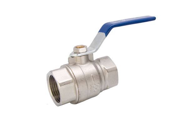
                    Understanding Ball Valve Internal Leakage

                    Definition of Internal Leakage

                    Internal leakage in a ball valve occurs when fluid escapes within the valve body itself, passing through the ball and seat interface even when the valve is in the closed position. This is different from external leakage, where fluid leaks from the valve body into the surrounding environment due to issues with seals or body connections. Internal leakage typically occurs when the ball or seat seals within the valve wear down, corrode, or become damaged, compromising the valve’s ability to form a complete seal. The result is unintended flow through the valve, impacting the controlled flow that the system requires.

                    Impact on Systems

                    Internal leakage in a ball valve can have a significant impact on a fluid control system, leading to a range of operational and financial challenges:

                    Reduced Efficiency: When a ball valve leaks internally, it allows fluid to bypass the intended closed-off state, which can decrease the system’s efficiency. For example, in a pressurized system, internal leakage can reduce flow control precision and make it harder to maintain desired pressure levels.

                    Safety Risks: In systems handling hazardous or high-pressure fluids, internal leaks can pose serious safety risks. Uncontrolled leakage may lead to unplanned pressure build-up, overheating, or exposure to harmful substances, which can endanger personnel and equipment.

                    Increased Maintenance Costs: Constant internal leakage accelerates wear on the valve components, often leading to frequent repairs or replacements. Regular maintenance to address leakage issues can become costly, especially in systems with multiple valves.

                    System Downtime: When leaks go undetected or worsen, they can lead to unplanned downtime for repairs. In critical operations, this downtime can cause operational delays, impact production targets, and increase overall costs.

                    In severe cases, repeated internal leakage may require a full valve replacement if the issue cannot be resolved through regular maintenance or part replacements. Understanding these impacts underscores the importance of prompt detection and repair.

                    Ball Valve Leaking Internally

                    Symptoms of Internal Leakage

                    Identifying internal leakage early can prevent further system issues and allow for timely repairs. Here are some key indicators of internal leakage:

                    Unusual Pressure Drops: A sudden or unexplained drop in pressure could indicate that fluid is escaping within the valve. If pressure levels cannot be maintained or controlled as expected, it may be due to internal leakage within one or more ball valves in the system.

                    Continuous Flow When Closed: If a ball valve continues to allow fluid through even in its fully closed position, this is a clear sign of internal leakage. This could manifest as a small trickle or drip, which may increase over time if the valve components are further damaged or worn.

                    Irregular Fluid Levels: In closed systems where fluid levels are carefully monitored, unexpected fluctuations can indicate an internal leak. When fluid levels change without explanation, it could mean that fluid is escaping internally through a closed valve.

                    Temperature Variations: Internal leakage can cause unusual temperature fluctuations within a system, especially in applications where fluid flow affects cooling or heating. For instance, if coolant flow is leaking within a closed valve, temperatures may rise unexpectedly, impacting system stability.

                    Noise or Vibration: In some cases, internal leakage can produce subtle sounds or vibrations as fluid passes through small gaps. Listening for unusual sounds near closed valves during regular inspections can sometimes help identify leaks before they worsen.

                    Common Causes of Internal Leakage in Ball Valves

                    Worn Seals or Seats

                    How and Why Seals Become Worn

                    The seals or seats inside a ball valve are essential for achieving a leak-tight seal when the valve is in the closed position. Over time, these components are prone to wear, which can compromise their sealing ability and lead to internal leakage. Seals and seats wear down for several reasons:

                    Aging: As seals age, they become less resilient and may start to crack or harden. Elastomer-based seals, such as rubber, are especially susceptible to aging, which can lead to a decline in their sealing efficiency.

                    Exposure to Harsh Chemicals: In systems that handle corrosive or chemically reactive fluids, seals may degrade prematurely due to chemical exposure. Harsh chemicals can erode seal materials, causing them to break down faster than expected, which opens gaps for fluid to escape.

                    Regular Operation and Abrasion: Each time a ball valve is opened or closed, the seals or seats experience a degree of friction against the ball. Over time, this friction leads to abrasion, which gradually wears down the surfaces. This effect is amplified in high-cycle applications, where the valve is frequently operated.

                    How Worn Seals Lead to Leakage

                    When seals or seats wear down, they can no longer maintain a tight seal, allowing fluid to pass through when the valve is closed. This internal leakage can worsen as the seals degrade further, increasing maintenance needs and potentially requiring full replacement of the valve.

                    Corrosion and Erosion

                    Effects of Corrosive and Abrasive Fluids

                    Corrosion and erosion are significant causes of internal leakage, especially in systems handling chemically aggressive or abrasive substances. Corrosion occurs when the valve material reacts with corrosive fluids, leading to the gradual breakdown of metal components. Over time, this weakens the structural integrity of the ball, seats, and seals. Erosion, on the other hand, happens when abrasive particles in the fluid wear down valve surfaces, leading to gaps and pitting.

                    How Corrosion and Erosion Cause Leakage

                    As corrosion or erosion progresses, it creates tiny channels or pits in the valve’s internal components, preventing a complete seal. This creates points where fluid can bypass the closed valve, resulting in internal leakage. Corrosion and erosion can be especially problematic in high-pressure systems, where even small imperfections can quickly expand under force, making leaks worse over time.

                    Poor Installation Practices

                    Effects of Incorrect Installation

                    Proper installation is crucial for ensuring that a ball valve operates effectively. Mistakes during installation, such as misalignment of parts, incorrect tightening, or failure to follow recommended torque specifications, can lead to premature valve failure and internal leakage. Here’s how specific installation errors contribute to leakage:

                    Misalignment: When the valve components are not properly aligned, the ball may not sit flush with the seats, preventing an effective seal. This gap allows fluid to bypass the seal, even when the valve is closed.

                    Over- or Under-tightening: If bolts or other fasteners are overtightened, it can compress or damage the valve seats, impairing their ability to form a seal. Under-tightening, on the other hand, may lead to loose components that shift during operation, causing leakage.

                    How Installation Errors Lead to Leakage

                    These installation errors can prevent the ball from fully closing off the flow, creating gaps in the valve’s internal seal. To avoid these issues, it is essential to follow manufacturer guidelines for installation, torque settings, and alignment, and to use trained personnel for the installation process.

                    Ball Valve Leaking

                    Pressure and Temperature Variations

                    Impact of Pressure and Temperature Extremes

                    Extreme or fluctuating pressures and temperatures can weaken valve components and contribute to internal leakage. High pressure can deform or warp valve seats and seals, especially if the valve is not rated for the specific operating pressure. Similarly, extreme temperatures can cause seals to expand, contract, or lose elasticity, leading to a compromised seal.

                    How Variations Cause Leakage

                    When pressure or temperature exceeds the valve’s design specifications, the integrity of the sealing surfaces is often compromised. For instance, high pressure can push the ball against the seats with excessive force, causing deformation. As the valve cycles through extreme temperatures, the expansion and contraction of materials can also create micro-gaps that allow fluid to bypass the closed valve. To avoid this, it’s essential to choose valves rated for the specific pressures and temperatures they will encounter.

                    Damage from Handling or Transportation

                    Risk of Damage During Shipping and Installation

                    Valves can sustain damage during shipping, handling, or installation, which may lead to internal leakage. Impacts, drops, or improper handling can damage the delicate sealing surfaces or misalign the internal components, which compromises the valve’s ability to achieve a tight seal.

                    How Handling Damage Leads to Leakage

                    If the ball or seats are damaged or misaligned, the valve may not close properly, resulting in leakage. Even minor dents or scratches can disrupt the valve’s ability to form a complete seal. Ensuring that valves are carefully handled during transport and storage is essential to maintain their performance.

                    Material Incompatibility

                    Selecting the Right Materials for the Fluid Type

                    Using incompatible materials for specific fluid or environmental conditions can lead to premature valve failure and internal leakage. For instance, a valve designed for water may not perform well in a system carrying corrosive chemicals or abrasive slurries. Material incompatibility often results in accelerated degradation of the valve components, particularly the seals and seats.

                    How Incompatibility Leads to Leakage

                    When the valve’s materials are not suited to the fluids they are exposed to, chemical reactions or physical wear can damage internal components. This compromises the seal integrity and leads to leaks. For example, if a rubber seal is used with a hydrocarbon-based fluid, the seal may swell, harden, or deteriorate, resulting in leakage. Choosing materials specifically suited to the application’s fluid properties is essential for long-lasting performance and leak prevention.

                    Solutions for Fixing Internal Leaks in Ball Valves

                    Internal leakage in ball valves can disrupt system efficiency, increase maintenance costs, and compromise safety. Addressing the root causes of these leaks and implementing solutions tailored to your system’s needs can prevent recurring issues.  

                    Replacing Worn Seals or Seats

                    Worn or degraded seals and seats are among the most common causes of internal leakage in ball valves. Replacing these parts can often restore the valve’s integrity.

                    Step-by-Step Guide to Replace Seals and Seats:

                    Preparation: Ensure the system is depressurized and drained. Close off any fluid flow to the valve and disconnect it from the pipeline.

                    Disassembly: Use the manufacturer’s instructions to disassemble the valve. Remove the handle or actuator, then access the valve body by removing bolts or screws.

                    Remove the Old Seals and Seats: Carefully extract the worn seals and seats from the valve body. Note their positions and orientation.

                    Inspect the Valve Components: Check for any other signs of damage, such as corrosion on the ball or scratches on the sealing surfaces.

                    Install New Seals and Seats: Place the replacement seals and seats in the correct positions. Ensure they are correctly aligned to provide a tight seal.

                    Reassemble the Valve: Reattach the valve body, handle, and any removed parts, following the manufacturer’s torque specifications.

                    Testing: Once the valve is reinstalled, conduct a leak test to verify that the internal leakage has been resolved.

                    Regularly inspecting and replacing seals can help maintain valve performance, especially in high-cycle or high-pressure applications.

                    Cleaning and Maintenance

                    Over time, debris, sediment, or chemical residues can accumulate inside ball valves, especially in systems handling abrasive or viscous fluids. Regular cleaning and maintenance are essential for preventing buildup that can wear down seals or interfere with proper closure.

                    Cleaning Routine for Ball Valves:

                    Flush the System: Periodically flush the system with a compatible cleaning agent to remove debris. This is especially important for systems handling viscous or particulate-laden fluids.

                    Inspect and Wipe Down Seals: During maintenance, inspect the seals and seats for buildup or wear. If buildup is present, clean the surfaces with a soft cloth and a solvent recommended for the seal material.

                    Lubrication: For valves with metal seats, apply a lubricant compatible with the valve material to reduce friction and prevent premature wear. Ensure that the lubricant does not degrade the seal material.

                    Corrosion Prevention: For valves exposed to corrosive environments, apply a corrosion inhibitor as recommended by the manufacturer. This will protect exposed metal parts and reduce the risk of leaks.

                    Tips for Maintaining Seal Materials:

                    For Rubber Seals: Avoid using solvents or cleaners that could cause swelling or hardening.

                    For PTFE Seals: PTFE is highly resistant to chemicals but should still be inspected for cracks or wear, especially in high-temperature applications.

                    For Metal Seals: Keep them lubricated and check for signs of corrosion, particularly in applications with aggressive chemicals.

                    Ball Valve Leaking repair

                    Correcting Installation Issues

                    Improper installation can result in misalignment or damage that leads to internal leaks. Follow this checklist to ensure proper valve installation.

                    Installation Checklist:

                    Alignment: Confirm that the valve is aligned correctly with the pipeline. Misalignment places stress on the seals and seats, compromising their ability to seal fully.

                    Torque Requirements: Tighten bolts and connectors to the manufacturer’s recommended torque. Over-tightening can deform seals, while under-tightening may leave components loose.

                    Seating Adjustments: Ensure that the ball and seats are properly aligned during installation. Misaligned seats can lead to internal leakage.

                    Avoid Excessive Force: Use the correct tools and avoid applying excessive force when handling sensitive parts like seals and seats.

                    By following proper installation procedures, operators can prevent premature valve wear and improve the longevity of the seals and seats, minimizing the risk of internal leaks.

                    Material Upgrades

                    The materials used in ball valves play a critical role in their ability to withstand specific operating conditions. Upgrading to more durable materials can help reduce the risk of leaks, especially in aggressive or high-pressure environments.

                    Choosing the Right Materials:

                    Stainless Steel: For systems exposed to corrosive fluids or extreme temperatures, stainless steel provides excellent corrosion resistance and can withstand temperature fluctuations.

                    PTFE-Coated Seals: PTFE coatings offer high chemical resistance and reduce friction. PTFE seals are ideal for applications with chemical exposure or high temperatures.

                    Hardened Metal Seals: In high-pressure or abrasive environments, hardened metal seals may be preferred over softer materials like rubber or elastomers, which wear down more quickly.

                    Ceramic Coatings: For particularly harsh environments, ceramic-coated balls and seats offer exceptional durability against erosion and chemical attack.

                    By selecting materials that match the operating environment, operators can enhance the valve’s performance and reduce the frequency of internal leaks.

                    Pressure and Temperature Adjustments

                    Extreme or fluctuating pressures and temperatures can stress valve components, leading to deformation, wear, and leakage. Adjusting these parameters can help protect valve components.

                    Adjustments to Reduce Stress on Valve Components:

                    Pressure Dampening: Use pressure dampening devices or adjust system pressure settings to reduce the impact on valve components. This is especially useful in systems with high-pressure surges.

                    Temperature Control: Maintain consistent temperatures or install temperature controls to prevent excessive expansion or contraction of valve materials. In some cases, insulating the valve or pipeline can help maintain a stable temperature.

                    Pressure Relief Valves: Install pressure relief valves to prevent excessive pressure buildup within the system, which can protect seals and seats from damage.

                    By optimizing pressure and temperature settings, operators can significantly reduce the stress on valve components, extending the life of the valve and reducing leakage.

                    Reinforcing Valve Design

                    For systems under high pressure or where frequent leaks have been an issue, upgrading to a more robust valve design may be a practical solution. Trunnion-mounted ball valves and reinforced seals are examples of design improvements that can reduce leakage risks.

                    Advantages of Reinforced Valve Designs:

                    Trunnion-Mounted Ball Valves: Unlike floating ball valves, trunnion-mounted designs secure the ball in place, reducing wear on the seals and seats. This design is ideal for high-pressure applications as it minimizes the stress placed on sealing surfaces.

                    Double Block and Bleed: For critical applications, a double block and bleed design allows for a secondary seal, reducing leakage risks. This setup provides additional isolation and enables operators to detect and relieve any trapped pressure.

                    Metal-Reinforced Seals: In applications with high wear or chemical exposure, metal-reinforced seals provide additional durability and can handle higher pressures without deforming.

                    Conclusion

                    Proactive inspection and maintenance are key to extending the life of your ball valves and preserving system efficiency. By addressing potential issues early, you can avoid costly repairs, unplanned downtime, and operational disruptions. Schedule regular inspections, stay vigilant for signs of internal leakage, and take prompt action when needed.


                    FAQ

                    What causes internal leakage in ball valves?

                    Internal leakage is often caused by worn seals, corrosion, improper installation, extreme pressure or temperature fluctuations, and material incompatibility.

                    How can I tell if a ball valve is leaking internally?

                    Signs of internal leakage include unusual pressure drops, continuous flow when the valve is closed, irregular fluid levels, and strange noises or vibrations near the valve.

                    Can internal leakage be fixed by replacing seals or seats?

                    Yes, replacing worn or damaged seals and seats is a common solution to restore a ball valve’s sealing capability and stop internal leaks.

                    What maintenance can prevent internal leakage in ball valves?

                    Regular inspections, cleaning, lubrication, and checking for proper alignment during installation can help prevent internal leakage.

                    What materials are best to avoid internal leakage?

                    Materials like stainless steel, PTFE-coated seals, and corrosion-resistant alloys are excellent choices for preventing leaks in harsh conditions.

                    When should I consider replacing a leaking ball valve?

                    If a valve has persistent leaks despite repairs, or if it shows significant wear, corrosion, or structural damage, it may be time to replace it.

                    Ball Valve Design Explained banner

                    Ball Valve Design Explained: How It Controls Fluid Flow

                    Ball valves use a spherical ball with a hole (or bore) in the center to control fluid flow: when the hole aligns with the flow path, the valve is open; when it rotates 90 degrees to a perpendicular position, the flow is blocked. This straightforward mechanism makes them a popular choice for on/off control, with some designs also capable of throttling flow.

                    What is a Ball Valve?

                    A ball valve is a type of valve used to control the flow of fluids through a pipe or system. It operates using a spherical ball with a hole (or bore) in its center. The primary function of the ball valve is to regulate or stop the flow of liquid, gas, or vapor by rotating the ball within the valve body. When the hole aligns with the flow path, the valve is open, allowing fluid to pass. When the ball is rotated 90 degrees (a quarter-turn), the hole is perpendicular to the flow path, thereby blocking the flow completely. This on/off operation is highly effective for many applications where simple, quick fluid control is required.

                    Basic Components of a Ball Valve

                    The ball valve is made up of several key components that work together to regulate fluid flow:

                    Ball: The heart of the valve, the ball has a hole (bore) through its center. The position of the ball determines whether the valve is open or closed. The ball is typically made of durable materials such as stainless steel or brass, and its surface is often treated to resist corrosion.

                    Seats: The seats are the sealing surfaces that are in contact with the ball when it is in the closed position. Seats are generally made from materials like PTFE (Teflon), elastomers, or metal alloys depending on the application. These materials ensure a tight seal to prevent leakage.

                    Body: The body houses the ball and other components and is usually made from materials such as steel, stainless steel, or cast iron. It provides the structure and durability for the valve.

                    Stem: The stem connects the ball to the actuator or handle, transmitting the rotational motion needed to open or close the valve.

                    Handle: For manual ball valves, the handle allows the operator to rotate the ball and control the flow. In automated systems, the handle is replaced by an actuator.

                    Actuator: In automated ball valves, actuators (either electric, pneumatic, or hydraulic) control the movement of the ball. Actuators allow for remote or automatic operation of the valve, increasing efficiency and safety in industrial applications.

                    Ball Valve Design

                    How It Works

                    Ball valves operate with a quarter-turn mechanism. When the valve is open, the hole in the ball is aligned with the flow path, allowing fluid to flow through. When the valve is closed, the ball is rotated 90 degrees so the hole is perpendicular to the flow, completely blocking the fluid. This simple and efficient mechanism allows for quick operation, with the valve shifting between open and closed positions in just a quarter turn.

                    Advantages of Ball Valves

                    Ball valves are highly favored in various industries due to several advantages:

                    Quick Operation: The quarter-turn mechanism allows for fast opening and closing, which is ideal for applications requiring swift responses.

                    Durability: Ball valves are built to last, with components that can withstand high pressures, temperatures, and harsh chemicals. The absence of rubbing parts reduces wear and tear, contributing to a long operational life.

                    Tight Shutoff: Ball valves provide a tight seal when closed, preventing leakage. This is essential for industries like oil and gas, water treatment, and chemical processing, where leakage can lead to significant safety concerns and operational inefficiencies.

                    Ball Valve Design Types

                    Ball valves come in various designs, each tailored for different flow control applications and operating conditions. The primary types of ball valves are floating ball valves and trunnion ball valves, but there are also several specialized designs, including V-port, multi-port, and 3-way ball valves. Each of these designs offers distinct advantages, depending on the system requirements such as pressure, flow rate, and application type.

                    Floating Ball Valves

                    Design Features and How They Work

                    A floating ball valve is the most common type of ball valve, where the ball is not fixed in place but is instead “floating” between the valve’s two seats. The ball is held in place by the pressure of the fluid on the inlet side, which forces the ball against the downstream seat, creating a tight seal. When the valve is open, the ball rotates to align the hole with the flow path. In the closed position, the ball rotates 90 degrees, sealing off the flow path.

                    Key Characteristics:

                    The ball is free to move within the body.

                    Pressure from the fluid forces the ball against the downstream seat for a tight seal.

                    Simplicity in design and cost-effective.

                    Typical Applications and Ideal Use Cases

                    Floating ball valves are ideal for low- to medium-pressure systems and smaller pipe diameters. They are widely used in industries such as water treatment, chemical processing, and food & beverage where the pressures are not extreme, and ease of maintenance is crucial. Since they are generally lighter and more affordable than other types, they are often chosen for cost-sensitive applications where high-pressure capabilities are not needed.

                    Pros and Cons Compared to Other Types

                    Pros:

                    Cost-effective: Typically more affordable than trunnion ball valves due to simpler design and construction.

                    Compact and lightweight: Suitable for applications with limited space and lower weight requirements.

                    Simple design: Easier to repair and maintain.

                    Cons:

                    Pressure limitations: Not ideal for high-pressure or high-flow applications, as the ball is not fixed and can shift under heavy pressure, potentially affecting sealing performance.

                    Potential leakage: In higher-pressure systems, leakage can occur if the ball does not remain tightly sealed against the downstream seat.

                    Trunnion Ball Valves

                    How the Design Differs

                    Unlike floating ball valves, trunnion ball valves feature a fixed ball that is supported at both the top and bottom by trunnions (extensions or shafts that support the ball). This design prevents the ball from floating under pressure and helps distribute the force more evenly. The trunnions are typically supported by bearings that allow the ball to rotate smoothly.

                    Key Characteristics:

                    Fixed ball, supported by trunnions on both ends.

                    Suitable for large, high-pressure systems where the ball needs additional support.

                    Generally larger and more complex than floating ball valves.

                    Ideal Applications

                    Trunnion ball valves are designed for high-pressure, high-flow, and large diameter systems. These valves are most commonly found in industries such as oil and gas, petrochemical, and power generation, where they manage large volumes of fluid or gas under high pressure. They are used in critical pipelines, reactors, and process systems that require reliable performance even under demanding conditions.

                    Benefits and Limitations

                    Benefits:

                    High-pressure tolerance: Can handle much higher pressures than floating ball valves because the trunnions provide additional support and stability.

                    Large flow capacity: Suitable for large diameter pipelines and systems with high flow rates.

                    Reduced wear: The fixed ball design reduces stress on the valve components, leading to longer service life.

                    Limitations:

                    More expensive: Due to their more complex design and materials, trunnion ball valves are generally more costly.

                    Larger size: These valves tend to be bulkier, requiring more space for installation.

                    Ball Valve Types

                    Other Types of Ball Valves

                    V-Port Ball Valves

                    A V-port ball valve has a ball with a V-shaped notch instead of a full bore. This design is specifically for throttling applications where precise control over the flow rate is needed. The V-notch allows for more controlled flow regulation and better performance in applications requiring variable flow.

                    Key Characteristics:

                    Provides flow regulation rather than just on/off control.

                    Ideal for systems where controlling the flow rate is crucial, such as in chemical dosing, mixing processes, or steam control.

                    Multi-Port Ball Valves

                    Multi-port ball valves have more than two ports, which enables the valve to divert or mix flows in multiple directions. These valves are commonly used in diverging or mixing flow paths, where one inlet can supply multiple outlets or multiple inlets need to be combined into a single outlet.

                    Key Characteristics:

                    Available in 3-port or 4-port configurations.

                    Used in mixing, diverting, or isolating different flow streams in a single valve.

                    3-Way Ball Valves

                    A 3-way ball valve is a specific type of multi-port valve that allows for three different flow paths. These valves are highly versatile and are often used for multi-directional flow control. In typical applications, a 3-way valve can combine or split two flow streams into different directions, making it ideal for systems like bypass systems, circulating systems, and diverting flow in multiple directions.

                    Key Characteristics:

                    Can redirect flow to three different ports, offering excellent control in complex systems.

                    Common in applications that require mixing or diverting fluids.

                    How to Choose the Appropriate Type

                    When selecting a ball valve design, several factors must be considered to ensure optimal performance:

                    Fluid Type: Different fluids (liquids, gases, slurries) may require different materials and designs to handle corrosiveness, viscosity, and other properties.

                    Pressure and Temperature: High-pressure and high-temperature applications typically require trunnion ball valves for added support, while floating ball valves may suffice for lower-pressure systems.

                    Flow Control Requirements: For simple on/off control, a floating or trunnion ball valve may be suitable. For variable flow control, consider V-port or 3-way ball valves.

                    Size and Space: If space is a constraint, floating ball valves are often preferred due to their compact design. For large pipelines, trunnion ball valves or multi-port valves may be more suitable.

                    Budget: Cost can be a factor in choosing between a floating and a trunnion ball valve, as the latter tends to be more expensive due to its complexity and additional features.

                    Key Factors in Ball Valve Design

                    The design and performance of ball valves are significantly influenced by the materials used in their construction, the quality of seals and seats, and the configuration of the flow path and valve porting. Understanding these key factors is crucial when selecting or designing a ball valve for a specific application. Let’s explore how these components contribute to the overall functionality and longevity of ball valves.

                    Materials of Construction

                    The materials chosen for ball valve components play a critical role in determining the valve’s performance, durability, and suitability for different fluids and operating conditions. The most common materials used in the construction of ball valves are stainless steel, brass, plastic, and carbon steel, among others. Each material offers specific advantages and is selected based on the following key factors:

                    Common Materials:

                    Stainless Steel: This is the most widely used material for ball valves, especially in applications that require high strength and corrosion resistance. Stainless steel is ideal for a broad range of industries, including oil and gas, water treatment, and chemical processing. It resists oxidation and corrosion from aggressive fluids, including acids and salts, making it highly suitable for harsh environments.

                    Brass: Brass is often used for smaller, low-pressure ball valves, typically found in residential, commercial, or HVAC applications. It is resistant to corrosion from water and air but is not as robust as stainless steel when exposed to harsh chemicals or extreme temperatures.

                    Plastic (PVC, CPVC, PVDF): Plastic ball valves, made from materials like PVC or CPVC, are commonly used in industries that handle corrosive chemicals or where cost is a significant factor. These materials are lighter than metal, offer excellent corrosion resistance, and are ideal for chemical processing or water treatment. However, they may not be suitable for high-temperature or high-pressure applications.

                    Carbon Steel: Used primarily in industrial applications, carbon steel ball valves are highly durable and can withstand moderate pressure and temperature. However, they are prone to corrosion, so they are typically coated or lined to prevent degradation when exposed to corrosive fluids.

                    Material Choice Considerations:

                    Corrosion Resistance: In aggressive environments, materials like stainless steel or plastics such as PVDF are preferred due to their superior corrosion resistance.

                    Pressure and Temperature Ratings: Stainless steel and carbon steel are generally chosen for high-pressure and high-temperature systems, while brass or plastic may be suitable for lower-pressure and lower-temperature systems.

                    Cost: Plastic materials are more affordable but may not perform as well in extreme conditions. Brass and carbon steel can be more cost-effective than stainless steel but may lack the durability required for certain industrial applications.

                    Seals and Seats

                    Seals and seats are essential for ensuring that the ball valve provides a tight shutoff and prevents leakage when the valve is in the closed position. These components directly influence the valve’s reliability, operational lifespan, and performance.

                    Importance of Seals and Seats:

                    Seals: The primary role of seals is to prevent leakage along the valve stem, where the ball is actuated. Seals are typically made from materials that provide a reliable seal while withstanding the pressures and temperatures of the system.

                    Seats: The seats, often positioned between the ball and the valve body, ensure a tight fit when the ball rotates to the closed position, preventing fluid from bypassing the valve. The material and design of the seats are critical in determining the leak-tightness of the valve.

                    Types of Seal Materials:

                    PTFE (Polytetrafluoroethylene): PTFE is the most common seal material due to its excellent chemical resistance, low friction, and ability to perform at a wide range of temperatures. It is ideal for valves used in chemical, pharmaceutical, and food-grade applications.

                    Metal Seals: Metal seals are used in high-temperature, high-pressure, or critical service applications where PTFE or elastomer seals would fail. They provide excellent durability but may require more maintenance due to wear over time.

                    Elastomers (e.g., Viton, EPDM): Elastomeric seals are used in systems requiring flexibility and resilience. They offer good sealing properties at low pressures and are often used in applications involving water, gases, or low-temperature fluids.

                    Impact of Seal Materials on Performance:

                    Durability: Seals made of PTFE or elastomers are typically softer and more susceptible to wear over time, especially in high-pressure or high-temperature environments. Metal seals, while more durable, may not offer the same flexibility or chemical resistance.

                    Leak Tightness: The seal material’s compatibility with the fluid and temperature directly affects the valve’s leak-tight performance. Inconsistent seal design or material choice can result in fluid leakage, compromising the system’s integrity.

                    Valve Life: A poor-quality seal or inappropriate material can cause valve failure, leakage, or the need for frequent replacements, thus affecting the valve’s operational life and maintenance costs.

                    Flow Path and Valve Porting

                    The flow path and porting configuration are critical elements that affect the flow rate, pressure drop, and overall flow efficiency of a ball valve. The design of the valve porting determines how the fluid flows through the valve, and choosing the right configuration is essential for meeting system requirements.

                    Port Configurations:

                    Full Port: A full port (or full bore) ball valve has an internal bore that matches the pipe diameter, ensuring minimal flow resistance and little to no pressure drop. Full port valves are typically used in applications that require high flow rates and low pressure loss, such as in large pipelines or HVAC systems.

                    Reduced Port: A reduced port valve has a smaller internal bore compared to the pipe size, creating a constriction in the flow path. This design is often used where space is limited or where flow rates do not need to be as high. The reduced port will create a pressure drop, but this may be acceptable in many standard applications, such as residential or commercial systems.

                    V-Port: A V-port valve features a V-shaped notch in the ball to provide precise flow control. This type of valve is used in throttling applications where the flow needs to be adjusted or regulated over time. The V-shaped opening allows for more gradual control of the flow rate compared to a standard full port.

                    How the Size of the Port Affects Flow Capacity:

                    The port size directly influences the flow capacity and pressure drop across the valve. A larger port allows for greater flow and lower pressure drop, making it suitable for high-flow applications. A smaller port restricts flow and increases the pressure drop but can be useful in applications where precise control of flow is needed, such as in throttling or mixing applications.

                    Choosing the Correct Port Configuration:

                    The choice between full port and reduced port configurations depends on several factors:

                    Flow Requirements: If high flow rates are required, full port ball valves are typically preferred. For moderate flow or low-flow systems, reduced port valves may be more economical.

                    Pressure Drop: Full port valves are ideal for maintaining low pressure drops, while reduced port valves are better suited for applications where the minor drop in pressure is acceptable.

                    Cost and Space Constraints: Full port valves are typically more expensive and bulkier than reduced port valves, so these considerations must be balanced based on system needs.

                    Ball Valve Actuation and Automation

                    Manual Actuation

                    The Role of a Lever or Handle

                    Manual actuation is the simplest and most traditional method of controlling a ball valve. A lever or handle is attached to the valve stem, and by turning the lever, the operator can rotate the ball inside the valve body to either open or close the valve. This rotation is a quarter-turn action, meaning the handle rotates 90 degrees to change the valve from an open to a closed position (or vice versa).

                    In manual ball valves, the handle is typically positioned to show the status of the valve (open or closed), providing a visual indication of the valve’s position. For smaller valves, this system offers a simple, cost-effective way to regulate fluid flow without requiring complex equipment.

                    Suitability for Smaller, Lower-Pressure Applications

                    Manual actuation is best suited for smaller, lower-pressure applications. These can include residential or commercial systems, HVAC installations, water treatment facilities, or smaller pipelines. Manual valves are often used in systems where frequent operation is not required and where the cost of automation is not justified. Additionally, they are ideal for situations where precise, remote control is not needed.

                    While manual ball valves are easy to install and maintain, they do require direct operator involvement, which can lead to inefficiencies in larger, more complex systems.

                    Signs Your Ball Valve Off Position

                    Automated Actuation

                    Pneumatic, Hydraulic, and Electric Actuators

                    Automated ball valves are controlled by external actuators, which are powered by pneumatic, hydraulic, or electric sources. Each type of actuator offers distinct advantages depending on the application’s power requirements and operating conditions.

                    Pneumatic Actuators: These actuators use compressed air to move the ball inside the valve. Pneumatic actuators are commonly used in systems that require quick, reliable operation and where compressed air is readily available. They are widely used in oil and gas or chemical processing industries, where fast shutoff and reliable operation are crucial.

                    Hydraulic Actuators: These actuators use hydraulic fluid (oil or water) to create the movement needed to open or close the valve. Hydraulic actuators are ideal for high-force applications, such as those in heavy industrial operations or power generation plants. They provide greater force compared to pneumatic actuators but require more complex systems.

                    Electric Actuators: Electric actuators use motors to turn the ball inside the valve. They are suitable for environments where a consistent power supply is available and where precise, controllable movements are required. Electric actuators are common in automation systems, including manufacturing, water treatment, and building management systems.

                    How Automation Impacts Performance, Efficiency, and System Control

                    Automating ball valves improves performance, efficiency, and system control in several ways:

                    Remote Control: Automated ball valves can be controlled remotely, making them ideal for systems that are difficult or dangerous to access. Operators can monitor and control valve positions from a central control room, minimizing the need for physical presence at each valve location.

                    Precise Control: Automated systems provide greater precision in adjusting the flow rate or pressure, especially when combined with flow meters or pressure sensors. This precision is particularly important in industries like chemical processing, where small changes in flow can have significant consequences on product quality or safety.

                    Operational Efficiency: Automation reduces the need for human intervention, streamlining processes and improving safety. In large systems, automated valves ensure that processes can continue to run smoothly without operator delays, contributing to higher throughput and reduced downtime.

                    Conclusion

                    In conclusion, choosing the right ball valve involves understanding the specific needs of your system, from flow requirements to pressure ratings and safety considerations. By carefully assessing the design and features of the valve, industries can ensure optimal performance, reduced downtime, and enhanced operational safety. If you need ball valves, please contact Topa now!


                    FAQ

                    What is a ball valve?

                    A ball valve is a type of valve that controls fluid flow using a spherical ball with a hole through its center. The ball rotates within the valve body to either allow or block the flow of fluid. It operates with a quarter-turn mechanism, meaning it opens or closes with a 90-degree rotation.

                    How does a ball valve work?

                    A ball valve works by rotating the ball inside the valve body. When the hole in the ball aligns with the flow path, the valve is open, allowing fluid to pass through. When the hole is perpendicular to the flow, the valve is closed, stopping the fluid.

                    What are the different types of ball valves?

                    The main types of ball valves are floating ball valves, which are used in low-pressure systems, and trunnion ball valves, which are designed for high-pressure applications and have trunnions (supports) to hold the ball in place.

                    What materials are ball valves made from?

                    Common materials for ball valves include stainless steel, brass, carbon steel, and plastics such as PVC. The choice of material depends on factors like corrosion resistance, temperature tolerance, and pressure requirements.

                    What’s the difference between full-port and reduced-port ball valves?

                    A full-port ball valve has an internal bore that matches the pipe diameter, offering minimal resistance to flow. A reduced-port ball valve has a smaller bore, which results in a higher pressure drop and reduced flow capacity, making it suitable for applications where flow rate is less critical.

                    Can ball valves be automated?

                    Yes, ball valves can be automated using pneumatic, hydraulic, or electric actuators. Automated ball valves provide benefits like remote operation, precise flow control, and enhanced safety features, such as fail-safe mechanisms for emergency shutoff.

                    Needle Valve vs Ball Valve banner

                    Needle Valve vs Ball Valve: Key Differences in Flow Control

                    While ball valves are known for their ability to provide rapid on/off flow control with a simple quarter-turn, needle valves are designed for precision flow regulation, allowing fine adjustments in low-flow applications.

                    Understanding Needle Valves

                    Definition

                    A needle valve is a type of valve used for precise control over fluid flow. Named for its slender, needle-like plunger, it allows for fine adjustments, which is essential in applications where accurate flow control is crucial. The design enables the valve to regulate flow with exceptional precision, especially in low-flow scenarios, making it ideal for tasks like sampling, calibration, and gradual pressure reduction.

                    Components

                    Needle valves consist of several key components that work together to control fluid flow finely:

                    Needle: The main control element, is tapered to fit into the valve seat, allowing fluid to flow around it in adjustable amounts. The needle’s sharp, pointed end allows for precise flow modulation.

                    Seat: The needle’s tapered tip sits into this seat, forming a tight seal when closed, preventing leakage. The seat is often made from materials that are compatible with the fluid being handled, enhancing durability.

                    Stem: The stem connects the needle to the handle or actuator, transmitting motion from the handle to the needle for control.

                    Body: The body houses the other components and provides the structure. Typically, needle valve bodies are made of durable materials like stainless steel, brass, or plastic, depending on the intended environment.

                    Needle Valve component

                    How It Works

                    Needle valves operate through a simple yet effective flow control mechanism. When the handle is turned, it rotates the stem, which raises or lowers the needle inside the valve body. The more the needle is lifted from the seat, the more fluid can pass around it, gradually increasing the flow. This threaded design enables fine adjustments, allowing operators to set the valve to the exact flow rate needed. As the needle moves closer to the seat, the flow rate decreases until the valve is completely shut off. This gradual control makes needle valves ideal for processes where small flow changes are necessary over time.

                    Advantages

                    Needle valves are highly valued for their ability to provide precise flow control. Unlike ball valves, which open and close quickly, needle valves are suited for applications where gradual flow modulation is critical. They are also well-equipped to handle high-pressure systems due to their robust construction, often withstanding pressures of up to several thousand psi. Their fine control allows for smooth, incremental adjustments, making them indispensable in sensitive applications where even minor fluctuations in flow or pressure can impact outcomes. Additionally, needle valves can achieve a tight shutoff, minimizing leakage, which is beneficial in applications involving hazardous or expensive fluids.

                    Applications

                    Due to their fine control capabilities, needle valves are common in a range of industries and applications where precise flow regulation is essential:

                    Laboratories: Needle valves are frequently used in lab settings for processes like sampling, testing, and calibration, where accurate flow rates are vital for experiments.

                    Pressure Regulation: In high-pressure systems, needle valves provide incremental adjustments to maintain stable pressures, ensuring equipment safety and performance.

                    Instrumentation: Needle valves are widely used in instrumentation setups, such as flow meters and pressure gauges, to ensure consistent and controlled flow for accurate readings.

                    Hydraulics and Pneumatics: These valves are utilized to control hydraulic fluid or compressed air in systems where slight changes in pressure or flow need to be finely managed.

                    Chemical Processing: Needle valves are often employed in the chemical industry for dosing and precise addition of chemicals into a process line, where control over flow is crucial to avoid reactions or contamination.

                    Needle Valves vs Ball Valves  

                    When choosing between needle valves and ball valves, it’s important to consider the specific needs of your system, such as flow control, pressure handling, and the level of precision required. While both are widely used for regulating the flow of fluids, their designs and functionalities are quite different. Below, we compare needle valves and ball valves across several critical parameters:

                    Flow Control Mechanism

                    Needle Valves:

                    Needle valves are specifically designed for fine, precise flow control. This precision is achieved through the tapered design of the needle, which fits into the valve seat. As the valve stem is rotated, the needle gradually moves into or out of the seat, regulating the flow rate incrementally. This allows operators to adjust the flow in very small amounts, making needle valves ideal for applications where detailed control is critical. The thread design of the needle allows for fine adjustments, making them perfect for controlling flow in systems where the flow rate must be monitored and carefully regulated.

                    The main strength of needle valves lies in their ability to control low-flow applications with high accuracy, such as in laboratory settings or in applications where very specific fluid volumes need to be controlled. This ability to fine-tune the flow makes needle valves unsuitable for applications requiring high flow rates, as they are designed for slow, controlled changes in flow.

                    Ball Valves:

                    In contrast, ball valves operate on a much simpler mechanism. The valve uses a hollow, perforated ball that rotates inside the valve body. When the ball’s hole is aligned with the pipeline, the valve is fully open, allowing fluid to flow freely. When the ball is rotated 90 degrees, the hole is no longer aligned with the flow path, and the valve shuts off the flow. This quarter-turn operation is fast and provides on/off control with a low operating effort.

                    Ball valves excel in applications that require rapid shut-off or full-flow regulation. Their operation is simple, which makes them ideal for high-flow systems or situations where quick flow shutoff or isolation is needed. However, ball valves are not well-suited for fine flow modulation. They typically perform best when the valve is either fully open or fully closed, and any in-between states can be difficult to manage without specialized designs, such as V-port ball valves.

                    Needle Valves

                    Flow Rate and Pressure Handling

                    Needle Valves:

                    Needle valves are designed to handle low flow rates and high-pressure situations. Their precision threading allows them to regulate fluid in systems that require tight control under high-pressure conditions, without introducing significant pressure drops. The fine adjustment mechanism is particularly useful in environments where the fluid flow must be reduced gradually or held steady under variable pressure conditions. However, needle valves tend to have a higher resistance to flow compared to ball valves, which limits their use in high-flow systems.

                    In terms of pressure handling, needle valves are particularly suited for situations where precise regulation is needed, even at high pressure. This is because their sealing mechanism is designed to withstand significant pressure without leaking. Therefore, needle valves are commonly used in applications like pressure reduction, flow metering, and hydraulic systems where managing flow precisely is critical to the safety and efficiency of the process.

                    Ball Valves:

                    Ball valves, on the other hand, are designed for high flow and low pressure drop systems. The design of the ball valve allows fluid to pass through with minimal resistance, making them ideal for applications involving larger flow rates. Because of their quick opening and closing action, ball valves are able to handle fluids in large pipelines or systems that require rapid shutoff, such as in gas distribution or water treatment systems.

                    When it comes to pressure handling, ball valves generally perform well under moderate to high pressure, but they are more suitable for applications where the flow rates are high and there is not as much need for fine control. Unlike needle valves, ball valves are better for systems that require less regulation of flow and more control over overall flow rate and system isolation.

                    Precision and Adjustability

                    Needle Valves:

                    Needle valves shine when it comes to precision and adjustability. Their design allows for incremental adjustments, giving operators the ability to make very small changes in flow rates. This level of precision is especially useful in applications where consistent, gradual flow is important. Needle valves are commonly used in pressure regulation and metering applications, where the ability to finely control flow can make a significant difference in the system’s performance.

                    The threaded needle design offers high control over flow, but it also means the operation of the valve is relatively slow, requiring more turns of the handle or actuator to make even minor adjustments. This makes them unsuitable for applications that require fast, frequent changes in flow rate. In systems that demand fine control over flow rate, needle valves are often preferred over other valve types, but their limitations in terms of speed and maximum flow capacity must be considered.

                    Ball Valves:

                    Ball valves are less suited for fine adjustments compared to needle valves. While ball valves do provide fast, on/off control, their design doesn’t support the same level of precise, incremental adjustments that needle valves do. Ball valves work best in applications where the primary need is for either full-on or full-off flow regulation, and they are typically used in systems where the flow rate is either fully open or fully closed, such as in pipeline isolation, shutoff valves, or diverting flow.

                    However, in certain cases, ball valves can be designed with specialized ports (like V-port ball valves) or actuators to achieve a degree of flow modulation, but even then, they can’t match the precision offered by needle valves. Ball valves are ideal for situations where the flow must either be completely allowed or completely stopped, and they are not intended for gradual changes.

                    Choosing the Right Valve: Needle Valve vs Ball Valve

                    Application Suitability

                    When to Choose a Needle Valve

                    Needle valves are best suited for high-precision control applications where fine adjustments to the flow rate are critical. Their primary advantage lies in their ability to provide incremental flow regulation, which is essential in sensitive systems that require controlled flow under specific conditions. Common applications for needle valves include:

                    Laboratory Settings: Needle valves are frequently used in research and laboratory environments where precise fluid flow is necessary for experiments, calibration, or testing. In these settings, even small fluctuations in flow can lead to incorrect results, so needle valves are ideal for providing the fine control needed to maintain accuracy.

                    Instrumentation: For processes requiring precise measurement of flow rates, needle valves are preferred. They are often used in conjunction with flow meters, pressure gauges, or other measurement devices, where precise flow control ensures accurate readings.

                    Pressure Regulation: In systems where pressure must be carefully controlled, such as in hydraulic or pneumatic systems, needle valves are commonly employed. They allow for gradual pressure adjustments, making them suitable for applications where a stable, controlled pressure is necessary over time.

                    Needle valves are generally used in applications with low to medium flow rates and high pressure, where the ability to make small, controlled changes in flow is more important than achieving a high flow rate.

                    Needle Valve application

                    When to Choose a Ball Valve

                    Ball valves, on the other hand, are designed for on/off flow control and are typically used in systems where a quick shutoff or isolation is needed. The simplicity of the ball valve’s quarter-turn operation makes it suitable for applications where speed and reliability are paramount. Common use cases for ball valves include:

                    Industrial Pipelines: Ball valves are widely used in industrial pipelines where the main requirement is to control large volumes of fluid. They are often used for isolation purposes, such as turning on or off the flow of water, gas, or other materials through large-diameter pipes.

                    HVAC Systems: In heating, ventilation, and air conditioning (HVAC) systems, ball valves are used to control the flow of air or water with minimal pressure drop. They are also employed to isolate sections of the system during maintenance or when balancing the system.

                    Gas and Chemical Handling: Ball valves are ideal for systems where the flow of gases or chemicals needs to be stopped or started quickly. They are often used in shutoff applications, such as in gas distribution systems or in the oil and gas industry.

                    Ball valves excel in environments that require rapid flow control, such as systems with high flow rates and frequent shutoff demands. Their ability to handle large volumes of fluid with minimal resistance makes them unsuitable for applications that require fine, precise adjustments.

                    Flow Control Needs

                    Needle Valves for Precise Flow Regulation

                    Needle valves are specifically designed for highly controlled, low-flow applications. The key feature that sets them apart from other valve types is their ability to offer very fine adjustments to the flow. This is achieved through the threaded needle design, which allows the operator to make incremental changes in the flow rate. As the needle is adjusted, the opening through which the fluid flows becomes narrower or wider, offering precise control.

                    Needle valves are commonly used in applications where gradual changes in flow are necessary, such as in laboratories, calibration setups, or instrumentation systems. They are also used to restrict flow in pressure control systems to ensure that the pressure stays within safe and optimal ranges.

                    Ball Valves for Rapid Flow Control and Isolation

                    Ball valves, due to their simple quarter-turn operation, are designed for rapid flow control and complete shutoff. Once the valve is opened, it allows fluid to flow unrestricted until it is turned off, at which point the flow stops completely. This makes them ideal for applications requiring quick, full-flow isolation. Ball valves are often used in systems where the flow needs to be either fully on or fully off, with little to no intermediate control.

                    In large industrial processes or piping systems, ball valves offer a quick response time and minimal flow resistance, making them the ideal choice for high-flow applications like water treatment plants, HVAC systems, or natural gas pipelines. While they cannot match needle valves for precision, they are well-suited for systems where the need for precise flow regulation is secondary to rapid on/off control.

                    Pressure and Temperature Considerations

                    Pressure Handling

                    Needle valves are typically used in high-pressure applications where flow must be controlled precisely. Their design allows for high resistance to pressure fluctuations, and they can handle pressures of several thousand psi in certain configurations. This makes them ideal for hydraulic systems, gas sampling, or fluid systems that operate under high pressure, where controlling the pressure and flow rate is crucial for maintaining the integrity of the system.

                    While ball valves can handle moderate to high pressures, they are generally not suited for the same extreme pressure control that needle valves can provide. Ball valves can withstand pressures up to a certain point, but their primary function is to allow for full-flow control, which can result in increased pressure drops when used in high-pressure systems.

                    Temperature Tolerance

                    Both needle valves and ball valves can be designed to handle a wide range of temperatures, depending on the materials used in their construction. However, needle valves are often chosen for more temperature-sensitive applications due to their ability to provide fine flow regulation at a wide range of temperatures. High-quality needle valves can be constructed with materials that resist temperature fluctuations, ensuring stable performance.

                    Ball valves are typically better suited for higher temperature ranges and general industrial use, but they are usually employed in systems where temperature control is less of a concern. They can handle hot fluids or gases as long as the flow is either fully open or fully shut, which is ideal for applications where temperature regulation is less complex.

                    Conclusion

                    When choosing between a needle valve and a ball valve, it is essential to first consider the nature of the flow (high or low), the required precision, and the pressure and temperature conditions of the system. Needle valves are the go-to choice when fine control and precision are needed, while ball valves are the best option for systems requiring quick and reliable flow shutoff. Always align the valve selection with the system’s operational needs to ensure optimal performance and longevity.


                    FAQ

                    What is the main difference between a needle valve and a ball valve?

                    Needle valves offer precise flow control with fine adjustments, while ball valves provide quick, full-flow shutoff or isolation with a simple quarter-turn mechanism.

                    Which valve is better for high-pressure systems?

                    Needle valves are typically better suited for high-pressure systems where fine flow regulation is necessary.

                    Can ball valves be used for flow regulation?

                    While ball valves are great for on/off control, they are not suitable for precise flow regulation like needle valves. They are ideal for systems with high flow rates.

                    Where are needle valves typically used?

                    Needle valves are commonly used in laboratories, instrumentation systems, and pressure regulation applications where precision is critical.

                    Are ball valves good for industrial pipelines?

                    Yes, ball valves are commonly used in industrial pipelines, providing fast and reliable isolation with minimal pressure drop.

                    Can needle valves handle high flow rates?

                    Needle valves are generally designed for low-flow applications. For high-flow needs, ball valves are the better choice due to their ability to manage larger volumes.

                    Soft vs Rigid Core banner

                    Soft vs Rigid Core: Which is Right for Your Hydraulic Hose?

                    Core selection is not just a technical detail but a critical factor influencing the overall efficiency, longevity, and reliability of hydraulic systems. The right core can enhance the lifespan of a hose, reduce maintenance costs, and improve performance in high-pressure or high-flexibility applications.

                    Understanding Hydraulic Hoses and Their Core Components  

                    Hydraulic Hose Basics

                    A hydraulic hose is a critical component in hydraulic systems, designed to convey pressurized fluid between various parts of the system, such as pumps, valves, actuators, and cylinders. Hydraulic hoses are used in numerous industries, including construction, automotive, agriculture, and manufacturing, where high-pressure fluid power is needed to operate machinery and equipment. The primary function of a hydraulic hose is to transfer hydraulic fluid under high pressure, and this fluid can be oil, water, or other liquids depending on the application.

                    What makes hydraulic hoses indispensable is their ability to carry fluid at very high pressures, typically ranging from 1,000 to 5,000 psi, depending on the application. The key to maintaining such high pressures without leakage or failure is the design and construction of the hose, specifically the core and the layers surrounding it. The core material of a hydraulic hose plays a significant role in determining its pressure tolerance, flexibility, durability, and overall lifespan.

                    Hydraulic hose components design Topa

                    Core Structure in Hydraulic Hoses

                    The core of a hydraulic hose is the central component that directly interacts with the fluid being transferred. It serves as the primary structural element that withstands the pressure and maintains the internal flow of fluid. The core is typically made from materials that can handle internal pressure while resisting wear and tear over time.

                    In addition to pressure tolerance, the core of a hydraulic hose must also be flexible enough to allow for the hose’s movement without breaking or kinking. This balance between strength and flexibility is one of the key considerations in designing hydraulic hoses. The core works in conjunction with additional layers, such as reinforcement (made from steel or synthetic fibers) and outer covers (designed for abrasion resistance and environmental protection).

                    The core also plays a crucial role in determining the hose’s ability to handle high and low temperatures, as well as its chemical resistance. If the core material is too rigid, the hose may be unable to flex or bend without cracking, which could lead to failure. Conversely, if the core is too soft, the hose may not be able to withstand the pressure of the fluid, resulting in leakage or bursting.

                    Types of Core Materials

                    There are two primary types of core materials used in hydraulic hoses: softcore and rigid core. Each material offers distinct advantages and is selected based on the specific demands of the hydraulic system.

                    Soft Core:

                    Soft core materials are typically made from synthetic rubber or thermoplastic elastomers (TPE). These materials are flexible, lightweight, and resistant to kinking, making them ideal for applications where the hose needs to bend or flex frequently, such as in machinery with moving parts. The flexibility of a soft core allows hydraulic hoses to navigate tight spaces and curve around obstacles without compromising the flow of fluid. However, soft core hoses are generally less resistant to high-pressure environments compared to their rigid counterparts.

                    Rigid Core:

                    Rigid core hoses are constructed with materials like steel, stainless steel, or composite materials. These materials provide greater strength and durability, allowing the hose to withstand higher pressure and more demanding environments. Rigid core hoses are typically used in static applications, such as in fixed industrial systems or where the hose must remain straight and resist mechanical stresses. While they offer superior pressure resistance, their lack of flexibility can limit their use in dynamic applications where bending and flexibility are required.

                    What is a Soft Core in Hydraulic Hoses?

                    Definition and Description

                    A soft core in hydraulic hoses refers to a central material that is flexible and adaptable, typically made from synthetic rubber, thermoplastic elastomers (TPE), or other flexible polymer compounds. Unlike rigid cores, which are built from materials such as metal or reinforced composites, soft cores prioritize flexibility and ease of handling. The material’s elasticity and capacity to bend without cracking or breaking make softcore hoses ideal for applications that require frequent movement or tight installation spaces.

                    The soft core is the innermost layer of the hydraulic hose, through which the hydraulic fluid flows. It is encased by one or more layers of reinforcement (such as braided steel or synthetic fibers) and an outer cover that protects against external elements like heat, abrasion, and chemicals. While soft core hoses are designed to handle high-pressure fluid systems, their main feature is the ability to flex and move without significant degradation of the hose structure.

                    The primary distinction between a soft core and a rigid core is in their flexibility. Soft core hoses are designed for dynamic systems where movement is a factor. In contrast, rigid core hoses are designed to maintain a fixed shape under pressure, making them better suited for static applications.

                    Advantages of Soft Core

                    The key benefits of soft core hydraulic hoses are tied to their flexibility, lightness, and ability to operate in dynamic environments. These advantages make soft core hoses an attractive choice for various industrial applications. Here’s a closer look at the major benefits:

                    Flexibility

                    The most notable advantage of soft core hydraulic hoses is their exceptional flexibility. Unlike rigid core hoses, which can be difficult to manipulate in confined spaces, soft core hoses can easily bend, twist, and curve without breaking. This flexibility allows for easier installation, especially in complex systems with limited access or tight corners. Additionally, soft core hoses can move with the equipment they are connected to, reducing the risk of damage due to bending or stretching.

                    Lightweight

                    Soft core hoses tend to be significantly lighter than their rigid counterparts, primarily due to the use of synthetic materials such as rubber and TPE. This reduced weight not only makes them easier to handle during installation and maintenance but also reduces the overall weight load on the hydraulic system. This feature is particularly important in mobile and heavy-duty equipment, such as construction machinery, where minimizing weight can enhance performance and fuel efficiency.

                    Resistance to Kinking

                    Another major advantage of soft core hydraulic hoses is their resistance to kinking. A kink in a hydraulic hose can cause serious issues in fluid flow, potentially leading to system malfunctions or even complete failure. The flexible nature of soft core hoses allows them to absorb bends and twists without compromising the internal flow of fluid. This makes them especially suitable for systems where hoses are subjected to frequent movement or positioning, such as in construction, agricultural, and automotive applications.

                    Suitable for Dynamic Applications

                    Soft core hoses are ideal for dynamic hydraulic systems, where the hoses must move, flex, or be repositioned during normal operation. For instance, construction machines like cranes, excavators, and bulldozers often use soft core hoses because of their ability to withstand bending, stretching, and vibration without failure. Similarly, agricultural machinery that operates in varied terrains benefits from soft core hoses, as these hoses can flex with the movement of the vehicle and the shifts in terrain.

                    Soft Core

                    Applications of Soft Core Hoses

                    Due to their flexibility, lightweight nature, and ability to resist kinking, soft core hoses are used across a wide variety of industries. Some of the key applications include:

                    Construction

                    In construction, heavy machinery such as excavators, bulldozers, and cranes rely on soft core hoses for hydraulic power. The hoses in these machines must endure constant movement and exposure to harsh environments, making the flexibility of a soft core essential. Additionally, construction equipment often operates in tight or irregular spaces, where rigid hoses would be impractical.

                    Agriculture

                    Agricultural equipment, including tractors, harvesters, and irrigation systems, frequently uses soft core hydraulic hoses. These machines often need to navigate rough, uneven terrain and deal with frequent adjustments, meaning flexibility and resistance to kinking are paramount. Soft core hoses allow farmers to operate equipment efficiently while minimizing the risk of hose failure in dynamic conditions.

                    Automotive and Transport

                    Soft core hoses are also used in automotive and transport systems, particularly in mobile hydraulic systems. They can be found in vehicles such as trucks, trailers, and buses, where flexible hoses are needed to manage hydraulic systems that may require frequent adjustments or exposure to movement.

                    Limitations of Soft Core Hoses

                    While soft core hoses offer numerous benefits, they are not without limitations. Understanding these limitations is crucial when selecting the right hose for a specific application:

                    Lower Pressure Ratings

                    One of the primary drawbacks of soft core hydraulic hoses is their lower pressure tolerance when compared to rigid core hoses. Due to the flexible nature of the core material, soft core hoses typically have lower pressure ratings, which means they may not be suitable for high-pressure hydraulic systems or applications where very high fluid pressure is required. While soft core hoses can handle moderate to high pressures, they may not be able to withstand extreme pressures found in industries like aerospace or high-performance industrial machinery.

                    Reduced Durability in High-Stress Environments

                    Soft core hoses tend to be less durable in environments where high temperatures, extreme abrasion, or chemical exposure are prevalent. While some soft core hoses come with protective covers to improve resistance to these factors, they are still more susceptible to wear and tear compared to rigid core hoses. In high-stress environments, soft core hoses may degrade faster, requiring more frequent maintenance and replacement.

                    Limited Use in Static Applications

                    Soft core hoses are best suited for dynamic, flexible applications. In static applications where the hose needs to remain fixed and resist movement, a rigid core hose is often more appropriate due to its superior structural integrity and pressure-bearing capabilities.

                    What is a Rigid Core in Hydraulic Hoses?

                    Definition and Description

                    A rigid core in hydraulic hoses refers to the central structural component made from materials that provide exceptional strength and stiffness, typically metal (such as steel or stainless steel) or composite materials. Unlike soft core hoses, which are designed for flexibility, rigid core hoses are engineered to maintain a fixed shape and resist deformation under high pressure. These hoses are ideal for applications that require structural stability and the ability to handle extreme conditions without losing their form.

                    The construction of a rigid core hydraulic hose involves a tough inner core, often reinforced with multiple layers to enhance its ability to withstand high pressures and environmental stress. The core is usually covered by several layers of reinforcement—such as braided steel wire, spiral wire, or synthetic fibers—that provide additional strength and resistance to mechanical damage. Finally, an outer protective cover shields the hose from abrasion, chemicals, UV light, and other environmental factors. This multi-layer design ensures that the hose can carry fluids under high pressure while remaining structurally intact.

                    Unlike soft core hoses, which excel in dynamic, flexible applications, rigid core hoses are better suited to static installations where movement is limited or not required.

                    Advantages of Rigid Core

                    The rigid core hydraulic hose offers several key benefits that make it the ideal choice for high-pressure, static applications. Here are the primary advantages:

                    Higher Pressure Tolerance

                    One of the most significant advantages of rigid core hoses is their ability to withstand much higher pressures compared to soft core hoses. The rigid materials used in the core provide increased structural integrity, which allows the hose to carry fluids under higher internal pressures without risk of deformation or failure. This makes rigid core hoses essential for systems that operate in environments where fluid pressure exceeds the limits that a soft core hose could safely handle. For example, they are commonly used in industrial applications and heavy-duty machinery that require fluid pressures of 5,000 psi or higher.

                    Durability in Harsh Environments

                    Rigid core hoses are known for their superior durability, especially in harsh environments. Their construction is designed to resist extreme conditions such as high temperatures, exposure to chemicals, abrasion, and mechanical stress. Rigid core hoses can be used in industries such as oil and gas, mining, and heavy machinery, where hoses are subjected to continuous wear and tear from abrasive materials, harsh weather conditions, and exposure to chemicals. The rigid core’s ability to maintain its structure over time, even under severe stress, contributes significantly to the hose’s lifespan.

                    Greater Structural Integrity

                    The rigid core provides enhanced structural integrity, meaning these hoses are less likely to collapse, expand, or deform when exposed to high pressure. The rigid material prevents the hose from becoming deformed under heavy loads, ensuring the fluid flow is consistent and uninterrupted. This characteristic makes rigid core hoses ideal for hydraulic systems where maintaining the integrity of the hose is critical for smooth operations, such as in large industrial machines and fixed hydraulic systems.

                    Better Suited for Static Applications

                    Rigid core hoses excel in static applications, where flexibility is not a primary concern. For example, in fixed installations such as those found in factories, power plants, or oil rigs, rigid core hoses can be laid out in a permanent configuration. They remain stable and reliable without the need for movement or repositioning. Rigid core hoses are typically used in high-pressure lines that require minimal flexing, providing an excellent solution where flexibility would add unnecessary complexity or risk to the system.

                    Rigid Core

                    Applications of Rigid Core Hoses

                    Rigid core hydraulic hoses are used in a wide range of industrial and high-pressure systems where the demands for durability and pressure resistance outweigh the need for flexibility. Some of the common applications of rigid core hoses include:

                    Industrial Machinery

                    Rigid core hoses are widely used in heavy-duty industrial machinery where high-pressure hydraulic systems are required. These include hydraulic presses, injection molding machines, and large construction equipment. In these systems, hoses must be able to handle constant high pressure without collapsing or degrading, making the rigidity of the core crucial. The use of rigid core hoses ensures long-lasting, reliable performance even in the most demanding conditions.

                    Oil & Gas Industry

                    In the oil and gas industry, hydraulic systems are exposed to extreme pressure and hazardous environments. Rigid core hoses are used to transfer fluids in offshore drilling rigs, refineries, and pipelines. These hoses can handle the high-pressure fluid transfer required for drilling operations while withstanding the corrosive nature of the chemicals and the harsh conditions at sea. Rigid core hoses are critical for ensuring that hydraulic systems in oil rigs continue to operate efficiently and safely under high-pressure conditions.

                    Mining

                    Mining operations use rigid core hydraulic hoses in the machines responsible for drilling, excavating, and transporting materials. These hoses are exposed to heavy-duty conditions, including extreme pressure and constant abrasion from dirt, rock, and other abrasive materials. The robust nature of the rigid core hose ensures it remains intact and functional even in the harshest of environments, providing consistent fluid transfer for mining equipment.

                    Limitations of Rigid Core Hoses

                    While rigid core hydraulic hoses offer several advantages, they also come with some limitations that need to be considered when choosing the right hose for an application:

                    Less Flexibility

                    The main limitation of rigid core hoses is their lack of flexibility. Unlike soft core hoses, which can bend and flex to accommodate movement, rigid core hoses are designed to remain straight and resist bending. This lack of flexibility can make installation more challenging in environments where hoses need to be routed through tight spaces or around obstacles. Additionally, rigid hoses are less suitable for dynamic systems that require frequent movement, as they can be prone to cracking or breaking when subjected to constant flexing.

                    Prone to Bending Under Stress

                    While rigid core hoses are durable, they can become susceptible to bending or damage under extreme mechanical stress. When subjected to bending forces beyond their design capacity, rigid core hoses may lose their structural integrity, leading to cracks or ruptures. This can be a particular concern in systems where the hose must be installed in areas subject to vibration or physical movement, as the rigid nature of the hose could lead to premature failure.

                    Conclusion

                    Choosing between a soft core and a rigid core hose depends on the specific needs of your hydraulic system. If your application involves constant movement, flexibility, and resistance to kinking, soft core hoses are likely the best option. For personalized advice on selecting the right core for your hydraulic hoses, consider reaching out to Topa.


                    FAQ

                    What is the difference between soft vs rigid core hydraulic hoses?

                    Soft core hoses are flexible and ideal for dynamic applications where frequent movement is required. Rigid core hoses are more rigid, providing higher pressure tolerance and durability, making them suitable for static or high-pressure systems.

                    When should I use a soft core hydraulic hose?

                    Soft core hoses are best used in applications that involve frequent movement, tight spaces, or bending, such as in construction, agriculture, and automotive industries.

                    What are the benefits of a rigid core hydraulic hose?

                    Rigid core hoses offer higher pressure resistance, greater durability in harsh environments, and better structural integrity, making them ideal for high-pressure, static applications like industrial machinery or oil and gas systems.

                    Can soft core hoses handle high pressure?

                    Soft core hoses can handle moderate to high pressures but are not suitable for extremely high-pressure systems. Rigid core hoses are preferred for applications requiring very high pressure.

                    Are rigid core hoses flexible?

                    No, rigid core hoses are not flexible. They are designed for static installations and are less suitable for dynamic systems that require bending or frequent movement.

                    How do I choose between soft core and rigid core for my hydraulic system?

                    Choose soft core hoses for flexibility and movement in low to medium-pressure systems, and rigid core hoses for high-pressure systems where structural integrity and durability are more critical. Always consider the specific demands of your application.

                    Preventing Broken Grease Fittings banner

                    Preventing Broken Grease Fittings: Common Causes and Fixes

                    Grease fittings are typically located at the joints or pivot points where parts move or rotate, which are susceptible to friction. Without these grease fittings, friction and wear would increase significantly, leading to premature breakdowns and frequent repairs.

                    Understanding Grease Fittings

                    A. What are Grease Fittings?

                    Definition and Purpose in Machinery

                    A grease fitting (also known as a zerk fitting, grease nipple, or lubrication fitting) is a small mechanical component used to inject lubricating grease into various parts of a machine. The fitting is designed to connect to a grease gun, enabling the technician or operator to deliver the appropriate amount of lubricant to components such as bearings, joints, and other moving parts that require regular lubrication to reduce friction and wear.

                    Grease fittings’ primary purpose is to ensure that machinery operates smoothly by maintaining optimal lubrication levels at critical points. By allowing easy grease injection into hard-to-reach areas, grease fittings help extend the lifespan of mechanical components, reduce wear and tear, prevent overheating, and ensure that the system runs efficiently without causing excessive damage to the equipment.

                    Types of Grease Fittings

                    Standard Grease Fitting: The most commonly used type of grease fitting, often referred to as a “Zerk fitting,” features a straight nozzle and can be used in various applications. It is widely used in automotive and industrial machinery.

                    Angled Grease Fitting: This fitting has a 45° or 90° angle, making it easier to grease components that are difficult to access. It is ideal for tight spaces or when the fitting is mounted in a location that is not easily reached with a straight fitting.

                    Button Head Grease Fitting: A button-shaped fitting, typically used in situations where space is extremely limited or where it may need to be flush against a surface. These are ideal for industrial and automotive applications where space is a concern.

                    Rotary Grease Fittings are used in rotating components, such as machinery where parts are continuously turned, such as axles or wheels. The rotating motion ensures that the grease fitting doesn’t obstruct the machinery’s operation.

                    Straight Grease Fitting: This type has a simple straight design and is used for standard applications where the fitting can be easily accessed. It is the most common and widely recognized style.

                    Each type of grease fitting has been designed with specific applications and equipment in mind, ensuring the correct flow of lubricant to critical components in the machinery.

                    high pressure grease fittings supplier

                    B. Common Materials and Construction

                    Material Selection for Durability

                    Grease fittings are typically made from durable metals designed to withstand high pressures and exposure to the harsh conditions they often face in machinery environments. The most common materials used for grease fittings include:

                    Steel: The most common material for grease fittings, steel offers a good balance of strength and cost-effectiveness. It is capable of handling high-pressure grease flow and is resistant to wear and tear.

                    Stainless Steel: For more demanding environments, such as those with high humidity, corrosive substances, or high temperatures, stainless steel grease fittings are used. These fittings are highly resistant to rust, corrosion, and wear, making them ideal for heavy-duty and harsh working conditions.

                    Brass: Brass is sometimes used for grease fittings in low-pressure applications. It is more resistant to corrosion than steel but may not be as durable or pressure-resistant for heavy machinery.

                    Zinc-Plated Steel: Zinc plating offers additional protection against corrosion, making it suitable for applications where grease fittings are exposed to moisture or outdoor environments.

                    Aluminum: In applications where weight is a concern, aluminum fittings may be used. However, they are generally not as durable as steel or stainless steel and are better suited for light-duty applications.

                    Material selection is essential to ensure that the grease fitting can handle the specific pressure requirements and environmental conditions where it will be used. The material must also be resistant to corrosion, wear, and impact damage to ensure a long lifespan.

                    Why Proper Fitting Choice Matters in Different Machinery Environments

                    Choosing the right grease fitting depends on several factors, including the type of machinery, the operating environment, and the required lubrication. Proper fitting selection is crucial because an incompatible or inappropriate fitting can lead to:

                    Premature Failure: Using a fitting that is not suited for the operating pressures or environment may cause it to break, leak, or become clogged, which would ultimately affect the entire lubrication system.

                    Corrosion: In corrosive environments (e.g., exposure to saltwater or harsh chemicals), using a fitting made from low-grade material such as standard steel might result in rusting, leakage, and premature failure.

                    Inadequate Lubrication: If a grease fitting is poorly designed or constructed, it might not allow proper grease flow, leading to inadequate lubrication and resulting in increased friction, wear, and potential damage to machinery.

                    Common Causes of Broken Grease Fittings

                    A. Over-tightening or Under-tightening

                    How Incorrect Torque Can Damage Fittings

                    Grease fittings require precise torque to ensure a secure and effective seal without causing damage. Over-tightening or under-tightening the fitting can cause serious issues:

                    Over-tightening: When a grease fitting is tightened beyond the recommended torque, it can lead to several problems. The excessive pressure can crack or deform the fitting, potentially making it difficult to attach the grease gun or causing it to break under pressure. Over-tightening can also distort the thread, which might lead to leaks or an inability to properly deliver grease.

                    Under-tightening: On the other hand, under-tightening a grease fitting can prevent it from creating a proper seal, resulting in grease leakage. Inadequate sealing also compromises the flow of lubrication to the system’s moving parts, which can cause friction and premature wear of components.

                    Signs of Improper Tightening and Risks Involved

                    Visible Cracks or Deformation: A fitting that has been over-tightened may show signs of cracks or deformities around the threads or the head.

                    Leakage: If a fitting is under-tightened, you may notice grease leaking around the fitting during lubrication.

                    Grease Infiltration Issues: A poorly tightened fitting may fail to deliver adequate lubrication to the necessary components, leading to increased friction and eventual component failure.

                    The risks involved include reduced equipment lifespan, frequent downtime, and potential damage to both the fitting and the surrounding machinery, leading to costly repairs.

                    Grease Fitting Clogged

                    B. Corrosion and Wear

                    Environmental Factors Leading to Corrosion

                    Grease fittings are often exposed to harsh environmental conditions, which can lead to corrosion over time. Some of the most common environmental factors contributing to fitting degradation include:

                    Humidity: In moist or humid environments, moisture can accumulate on the fittings, leading to rust and corrosion, especially in metal fittings that are not corrosion-resistant. This weakens the fitting material and reduces its lifespan.

                    Chemical Exposure: Chemicals, including acids, salts, or industrial cleaners, can accelerate the corrosion process. These substances can break down the metal, causing pitting and weakening the fitting structure.

                    Extreme Temperatures: High heat can cause metal to expand, leading to cracks or deformities, while extreme cold can make fittings brittle and more prone to cracking or breaking when force is applied.

                    How Regular Wear Affects Grease Fittings Over Time

                    Over time, grease fittings can wear out due to the constant pressure applied by the grease gun, exposure to contaminants, and environmental elements. As a result:

                    The fitting’s sealing ability can degrade, leading to grease leakage or loss of pressure during lubrication.

                    The fitting can become clogged with dirt, grease residue, or other debris, obstructing the flow of lubricant.

                    Wear and tear from constant movement or vibration can loosen or damage the fitting, causing it to fail and require replacement.

                    Regular inspection and maintenance are essential to detect early signs of wear and prevent more serious problems from developing.

                    C. Impact Damage

                    External Factors

                    Grease fittings are small, often located in tight spaces, and are vulnerable to impact damage. Common sources of impact include:

                    Tools: Mishandling tools, such as using the wrong size grease gun nozzle or applying excessive force, can cause the fitting to break or become misaligned.

                    Equipment: In high-impact areas, such as machinery that experiences vibration or machinery that undergoes frequent starts and stops, grease fittings can be subjected to physical forces that lead to cracks or dislodgement.

                    Rough Handling: During maintenance or repairs, grease fittings may get damaged due to improper handling or accidental impact when moving parts of the system.

                    Effects of Sudden Pressure Spikes or System Surges

                    Pressure Surges: In some hydraulic systems, pressure surges can occur when there is a sudden increase in system pressure due to system irregularities or malfunctioning components. These pressure spikes can damage fittings by causing them to dislodge, crack, or become misaligned.

                    Impact from Vibration: In systems subject to constant vibration or jolts (e.g., on trucks, construction machinery), fittings can be subjected to repeated impacts that weaken the fitting’s structure over time, causing them to break or fail unexpectedly.

                    D. Inadequate Lubrication

                    Poor Grease Quality or Improper Grease Application

                    Grease fittings rely on the proper quality and quantity of grease to lubricate machinery components effectively. Using poor-quality grease or the wrong type of lubricant for the specific application can cause several issues:

                    Inadequate Lubrication: Using grease that is too thick or too thin can lead to poor lubrication, increasing friction and wear on moving parts.

                    Contaminated Grease: A grease that contains contaminants like dirt or moisture can clog the grease fitting or cause abrasive wear on components.

                    Improper Application: Fittings that are not adequately greased may suffer from early signs of wear and tear. Over-greasing, on the other hand, can cause the grease to seep out and lead to contamination or loss of pressure.

                    How Lack of Maintenance Accelerates Fitting Failure

                    Without regular maintenance, grease fittings can become clogged, worn, or damaged. Over time, this lack of attention can cause the fitting to fail. For instance:

                    Clogging: If a fitting isn’t regularly lubricated or maintained, debris can accumulate in the fitting, causing it to become clogged and preventing the proper flow of grease.

                    Lack of Pressure: As grease degrades or if the lubrication system is neglected, the amount of pressure required to deliver grease through the fitting decreases, leading to inadequate lubrication and increased friction.

                    Neglecting to maintain grease fittings often accelerates the wear process, causing the fitting to fail prematurely and potentially leading to more severe machinery issues.

                    E. Poor Installation or Faulty Fittings

                    Manufacturing Defects in Fittings

                    Not all broken grease fittings are the result of wear or external factors. Manufacturing defects can contribute to fitting failures. Common defects include:

                    Incorrect Threading: Fittings with improperly threaded parts may not fit securely, leading to leaks or failures in sealing.

                    Weak Material: Some fittings may be made with materials that aren’t up to standard or poorly processed, leading to a weakened structure that can break or deform easily.

                    Defective Seals: Fittings that lack proper seals or gaskets may leak grease, causing inadequate lubrication and eventual breakdown of the fitting.

                    Mistakes During the Initial Installation Process

                    During installation, several mistakes can compromise the functionality of grease fittings, such as:

                    Misalignment: If a grease fitting is not aligned properly with the lubrication point, it may not provide adequate grease flow, leading to lubrication failure.

                    Sealing Issues: If the fitting’s seal isn’t properly secured, it may leak grease or fail to maintain adequate pressure, causing premature failure of both the fitting and the surrounding components.

                    Incorrect Size or Type: Installing the wrong size or type of fitting for a specific application can cause it to malfunction, especially if the fitting doesn’t fit properly with the system’s lubrication channels or if it is incompatible with the type of grease used.

                    Preventative Measures for Avoiding Broken Grease Fittings

                    A. Correct Installation Practices

                    Ensuring Proper Fitting Selection for Specific Equipment

                    The first step in preventing broken grease fittings is ensuring the right type of fitting is selected for each specific application. Different machinery and operating environments have varying lubrication needs, which dictate the fitting type and material:

                    Type Selection: Choose fittings based on the operational needs of the equipment. For instance, use angled or rotary fittings for hard-to-reach areas, button-head fittings in tight spaces, and straight fittings where they can be easily accessed.

                    Material Selection: Depending on the environment, you should opt for corrosion-resistant materials like stainless steel or zinc-plated fittings if the equipment is exposed to moisture, chemicals, or extreme temperatures.

                    Ensuring that fittings are designed to handle the expected pressure and environmental conditions helps reduce the risk of fitting failure.

                    Step-by-Step Guide on Installing Grease Fittings Correctly

                    Check Compatibility: Verify that the selected grease fitting matches the equipment and is compatible with the intended grease type.

                    Clean the Installation Area: Ensure the area where the fitting will be installed is clean and free of debris to prevent contamination that could affect the seal.

                    Align the Fitting: Ensure the fitting is properly aligned with the lubrication point. This ensures that grease is delivered efficiently without excess force.

                    Install the Fitting: Thread the fitting into place carefully by hand to avoid cross-threading. Use the appropriate tool to tighten it securely.

                    Torque Application: Apply the correct torque to avoid over-tightening or under-tightening, both of which can lead to fitting damage or failure.

                    Inspect for Leaks: Once installed, check the fitting for leaks to ensure that it is sealed correctly.

                    By following proper installation practices, you can significantly extend the life of the grease fitting and ensure that the lubrication system functions properly.

                    B. Regular Inspection and Maintenance

                    Developing a Maintenance Schedule for Checking Grease Fittings

                    Regular inspection is critical to identifying issues early and preventing broken grease fittings. Develop a comprehensive maintenance schedule that includes:

                    Routine Inspections: Check grease fittings at least every few weeks or months depending on the machine’s usage. Look for signs of damage, wear, corrosion, or leakage.

                    Lubrication Monitoring: Ensure that grease is applied at regular intervals. If grease fittings are clogged, damaged, or leaking, address them immediately.

                    Monitoring Pressure: Ensure that the system’s pressure is within the manufacturer’s recommended levels to avoid stress on the fittings.

                    Using Diagnostic Tools to Monitor Fitting Conditions

                    In addition to visual inspection, diagnostic tools can be used to assess the condition of grease fittings:

                    Grease Pressure Testers: These tools can help determine if the grease is being delivered properly through the fitting and if there are any blockages or pressure anomalies.

                    Infrared Thermometers: Use infrared thermometers to monitor temperature changes around fittings, as unusual temperature rises could indicate problems with lubrication or a failing fitting.

                    Ultrasonic Testing: For advanced diagnostics, ultrasonic sensors can detect signs of wear, corrosion, or vibration that might suggest a failing grease fitting.

                    By regularly inspecting and maintaining grease fittings, you can catch minor issues before they become major problems, reducing downtime and repair costs.

                    grease Fittings install Topa

                    C. Use of Quality Materials

                    Choosing Corrosion-Resistant and Durable Materials for Fittings

                    The material used for grease fittings plays a significant role in their durability and resistance to environmental factors. Selecting the appropriate material for fittings can prevent premature failure caused by corrosion, wear, and stress:

                    Stainless Steel: Ideal for harsh environments, stainless steel is resistant to corrosion from chemicals, moisture, and high temperatures, making it a top choice for heavy-duty machinery.

                    Zinc-Plated Steel: Provides additional corrosion resistance for environments that may experience rust, but it’s still affordable and effective for less demanding conditions.

                    Brass: While softer than steel, brass is used in applications where low pressure and light-duty use are required.

                    Durable Seals and Gaskets: Ensure that fittings come with high-quality seals or gaskets that can withstand heat, pressure, and contaminants.

                    The Role of High-Quality Grease in Prolonging Fitting Life

                    Using high-quality grease is just as important as selecting durable fittings. High-quality grease provides better lubrication, reduces friction more effectively, and prevents the buildup of contaminants. Choose grease specifically formulated for the equipment and operating conditions:

                    Consistency: Choose grease with the correct viscosity for the application. Grease that is too thick may cause clogging, while grease that is too thin may leak or fail to provide proper lubrication.

                    Additives: High-quality greases contain additives that help protect against oxidation, corrosion, and wear, which extends the life of the grease fitting and the components being lubricated.

                    D. Proper Torque Application

                    How to Use Torque Wrenches and Avoid Over-tightening

                    Torque application is critical when installing grease fittings, as both over-tightening and under-tightening can lead to issues. To avoid damage:

                    Use a Torque Wrench: Always use a torque wrench to apply the specified torque when installing a grease fitting. This ensures that the fitting is neither too tight nor too loose.

                    Avoid Over-tightening: Over-tightening a fitting can distort or crack the fitting, causing leaks, excessive stress on components, and possible fitting failure. The torque should be applied according to the manufacturer’s specifications, typically between 10 and 30 foot-pounds.

                    Proper Re-tightening: For fittings that may need periodic re-tightening, ensure that the torque specification is followed carefully to avoid damaging the fitting or surrounding parts.

                    Recommended Torque Specifications for Different Fitting Types

                    Torque specifications vary depending on the fitting type and size. It is essential to follow manufacturer guidelines for each type of fitting to avoid common issues:

                    Standard Grease Fittings: Typically, these require around 10–20 ft-lbs of torque.

                    Angled or Button Head Fittings: These fittings might require slightly less torque due to their design but should be tightened to the specifications provided by the manufacturer.

                    Heavy-Duty Fittings: Larger, heavy-duty fittings for industrial or agricultural machinery may require up to 30 ft-lbs of torque.

                    Following the correct torque specifications reduces the likelihood of damage and ensures that the fittings maintain their seal and pressure.

                    E. Environmental Considerations

                    Preventing Exposure to Harmful Elements Like Water, Salt, and Chemicals

                    Exposure to environmental factors such as water, salt, chemicals, or extreme temperatures can accelerate the breakdown of grease fittings. To prevent environmental damage:

                    Protect Fittings from Moisture: Ensure that grease fittings are kept dry and protected from excessive moisture or standing water, which can cause corrosion.

                    Use Protective Covers or Shields: Install protective covers or shields to shield grease fittings from external elements like dust, dirt, salt, and chemicals. This is particularly important for machinery used in marine environments or outdoors.

                    Regularly Clean Fittings: Clean grease fittings periodically to remove any accumulated debris, dirt, or grease buildup that might attract moisture or contaminants.

                    Implementing Protective Covers or Shields

                    Protective covers or boots can be used to shield grease fittings from damage in harsh environments. These covers protect the fitting from direct exposure to the elements, reducing the risk of corrosion, wear, and contamination. Use covers that are durable and specifically designed for grease fittings to ensure they remain effective over time.

                    Conclusion

                    We encourage you to prioritize grease fitting maintenance in your routine equipment care. Ensure that your fittings are in top condition, replace any worn-out or damaged parts, and don’t hesitate to reach out to professionals for assistance when needed.


                    FAQ

                    What are grease fittings and why are they important?

                    Grease fittings, also known as grease nipples, are components used to inject lubricants into machinery to reduce friction and wear. They are crucial for maintaining equipment, ensuring smooth operation, and extending the lifespan of moving parts.

                    What causes grease fittings to break?

                    Common causes include over-tightening or under-tightening, corrosion from environmental factors, impact damage, inadequate lubrication, and poor installation.

                    How can I prevent my grease fittings from breaking?

                    Preventative measures include using the correct fittings, applying the proper torque, regular inspections, using quality materials, and protecting fittings from environmental damage.

                    How often should I inspect grease fittings?

                    It is recommended to inspect grease fittings regularly, at least once a month or every few weeks depending on usage and environmental conditions. Routine checks can catch issues early.

                    What should I do if a grease fitting is damaged or leaking?

                    If a grease fitting is damaged or leaking, replace it immediately. Continuing to use a damaged fitting can lead to equipment failure or inefficiency in the lubrication system.

                    Can I install grease fittings myself?

                    Yes, as long as the proper installation procedures are followed. Ensure the fitting is aligned, torqued correctly, and compatible with the machinery. If you’re unsure, consulting a professional is a good idea.

                    Contact Topa

                    Save 30% on maintenance costs with our easy-install hydraulic fittings. Contact Now!