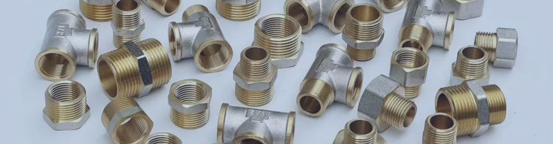
Is Your Brass Fitting Safe for Potable Water?
That small brass fitting in a drinking water system appears
That small brass fitting in a drinking water system appears
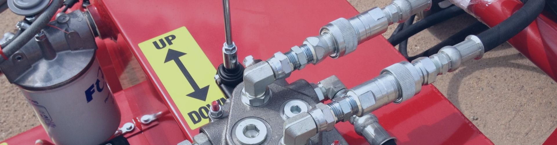
Selecting the right quick coupling seems simple, but a poor
Hydraulic quick couplings are designed for speed and efficiency, yet
A leaking hydraulic fitting on a tractor signals imminent downtime.
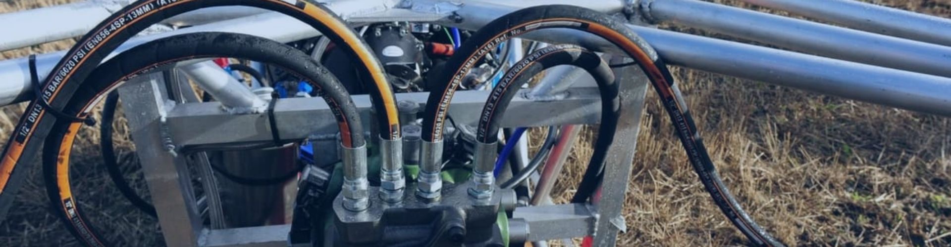
A mismatched thread or seal can bring your entire operation
Using the wrong hydraulic fitting causes leaks and system failure.

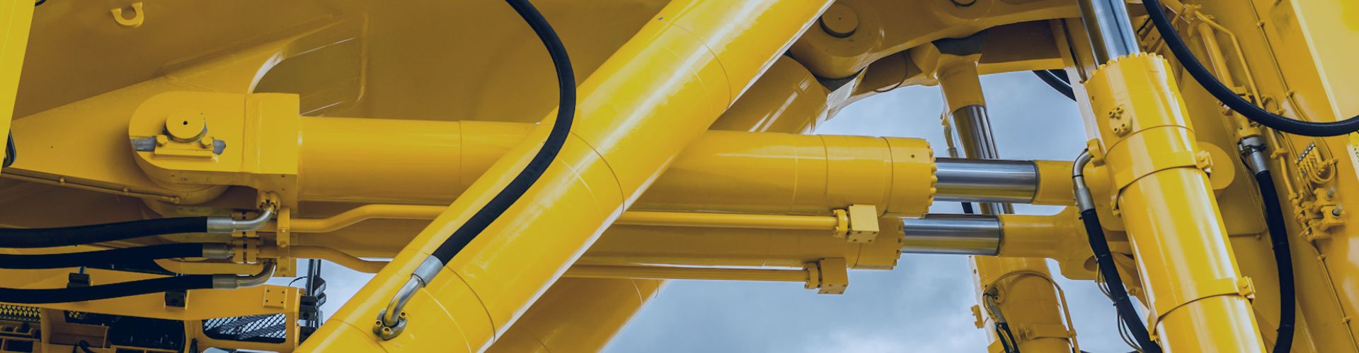
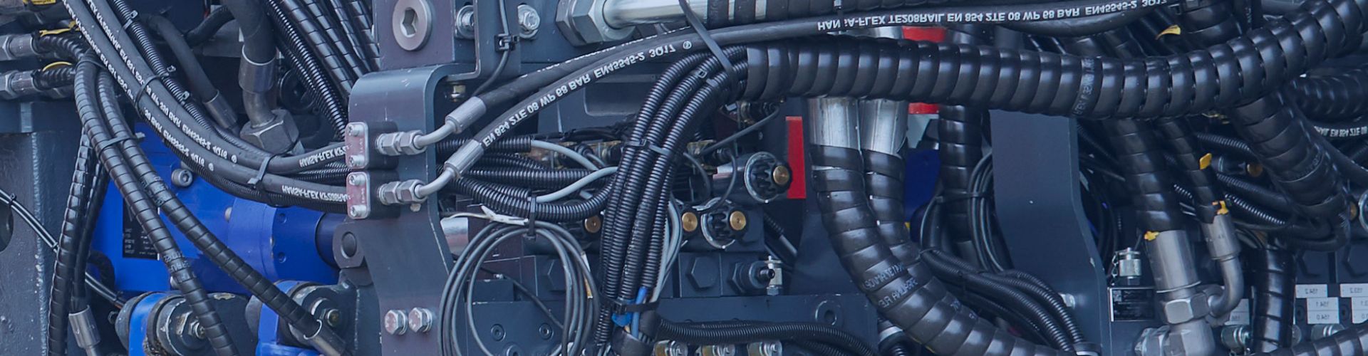
You need to replace a hose, but the specifications seem

Misinterpreting a hydraulic hose specification can lead to system failure.
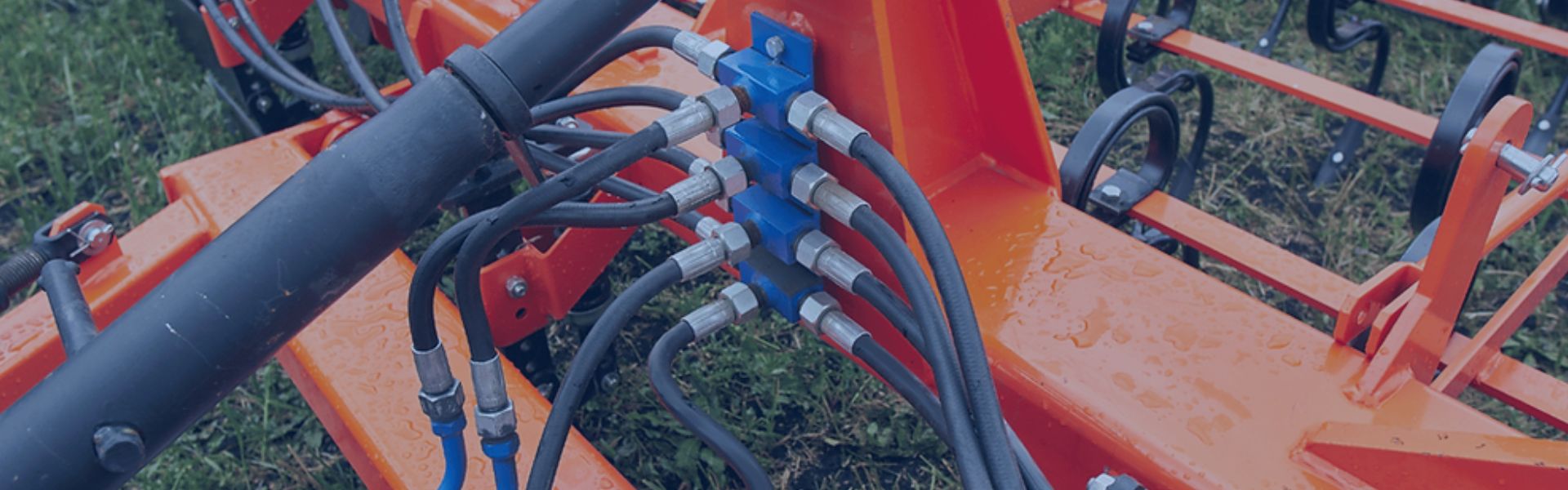
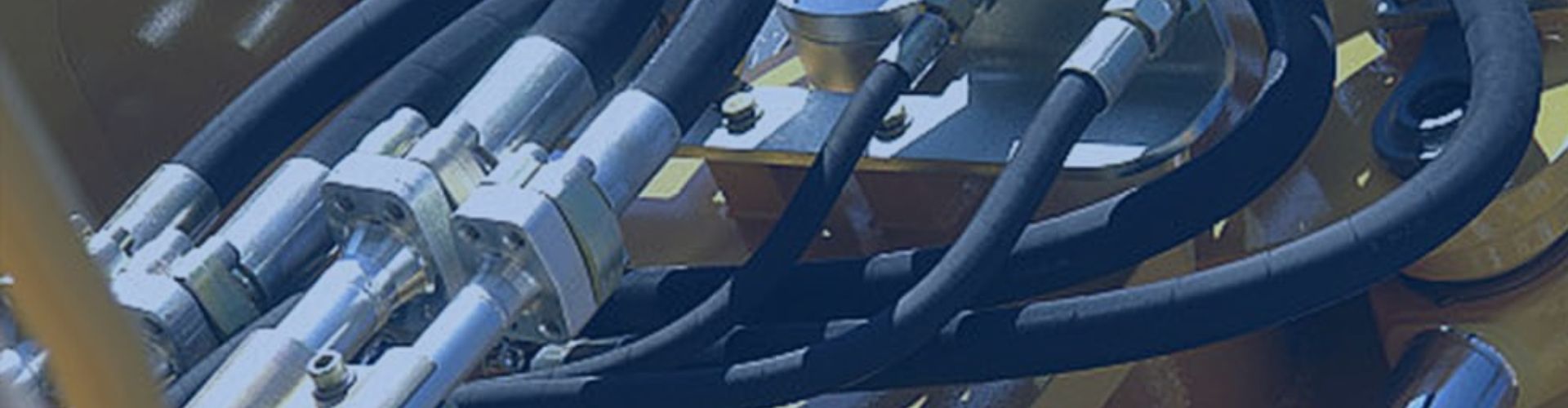
A persistent fluid leak from a threaded connection can indicate

You’re in the field, fighting to connect a hydraulic implement