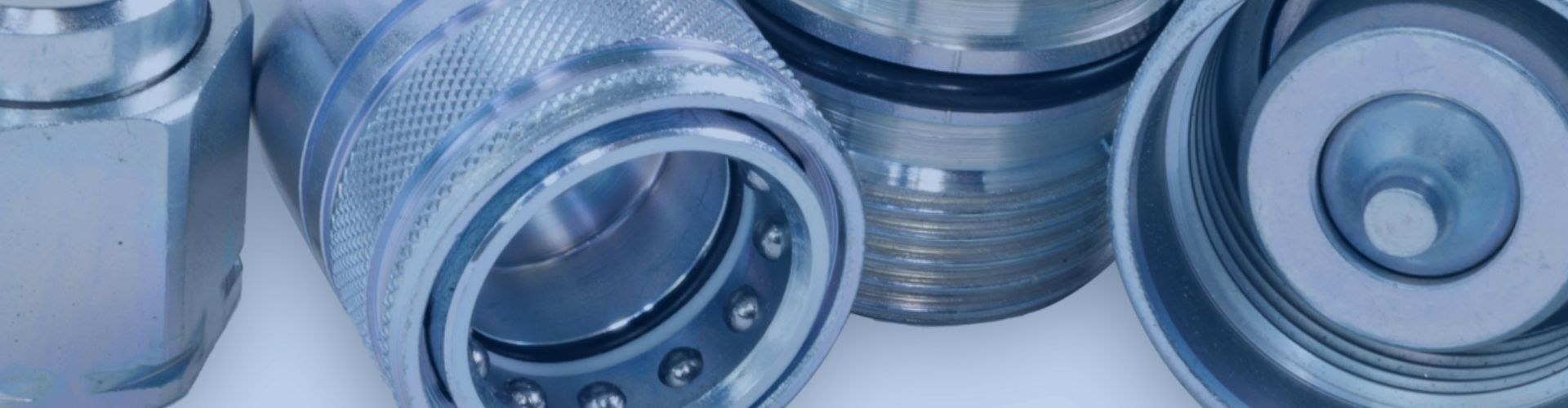
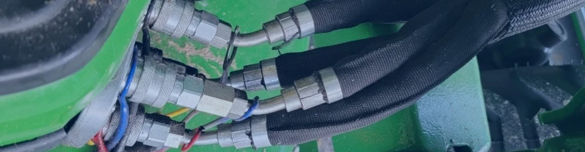
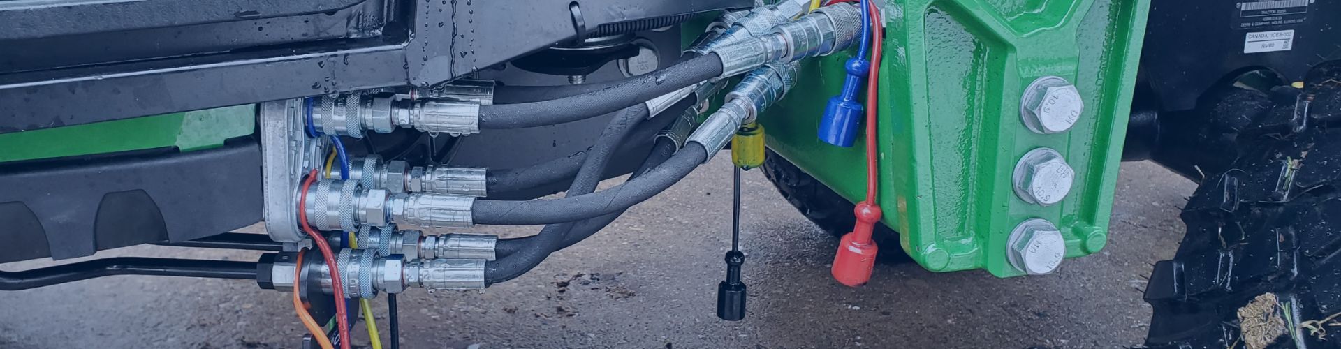
What are the Quick Coupling Connection Types?
Your system is down because a critical connection failed. Choosing
Your system is down because a critical connection failed. Choosing
You’re holding a hydraulic fitting, the production line is down,
You pick a fitting with a 5,000 PSI rating, assuming
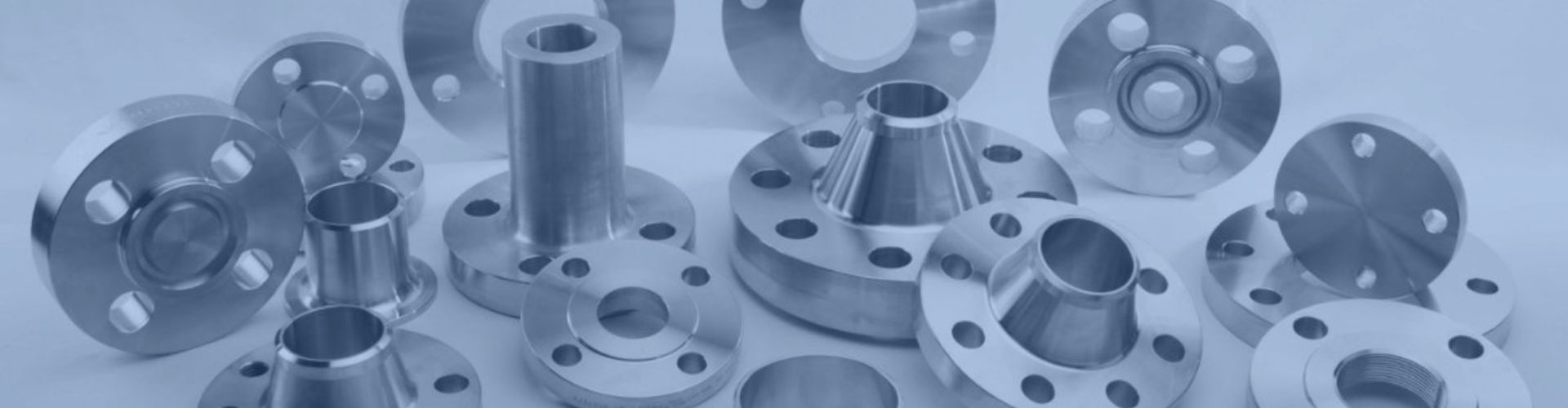
You select a flange that seems to fit, but a
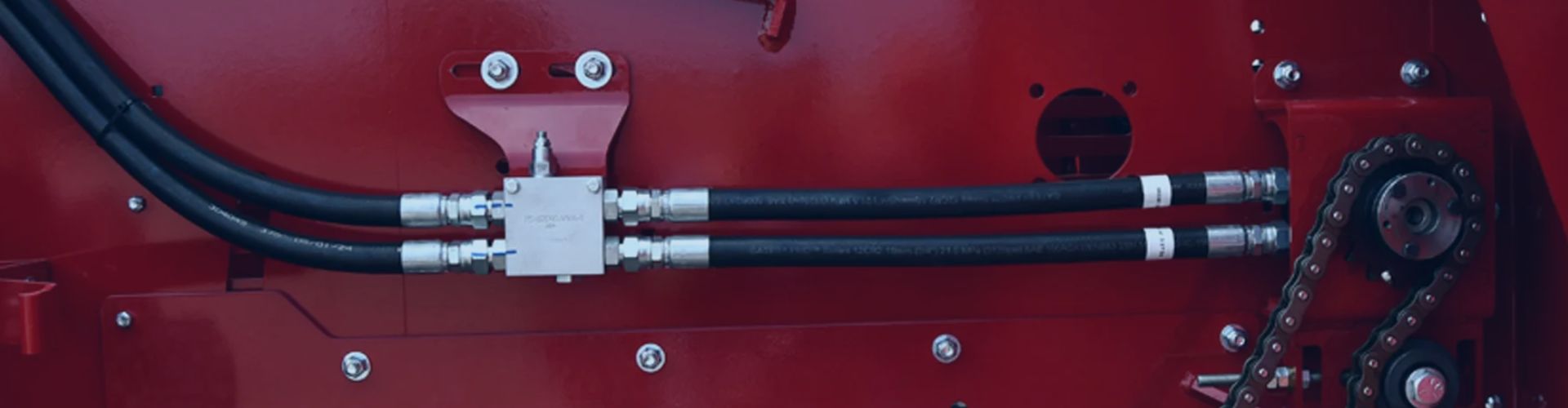
You grab a new hose that fits the port perfectly,
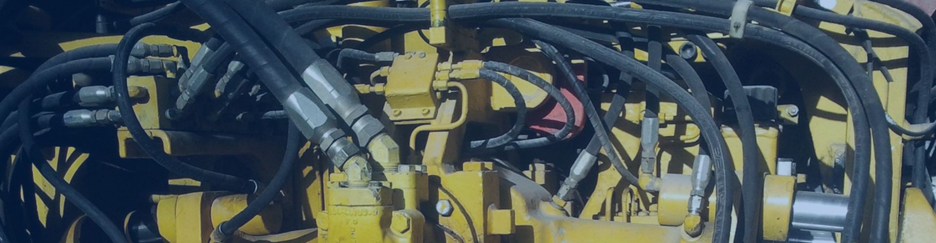
You need to disconnect a hydraulic line, but you’re dreading
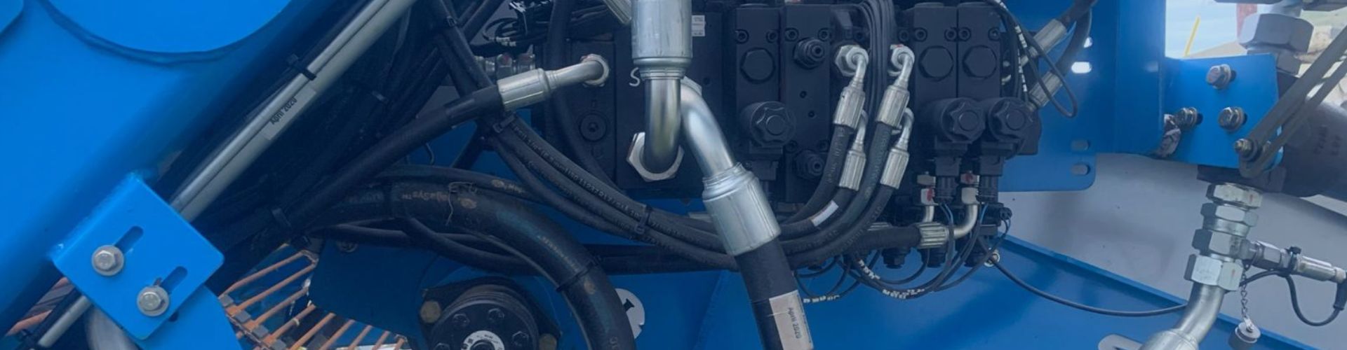
Your multi-ton rock drill grinds to a halt. A high-pressure
You look at a simple steel hydraulic fitting and it
A small leak in a water line is a nuisance.
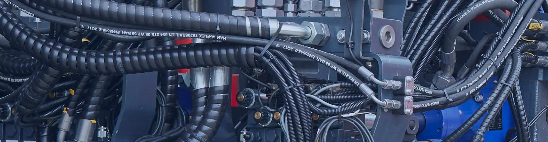
Choosing the wrong hydraulic hose can bring your entire job