7 Reasons Your Excavator’s Hydraulic Hoses Are Failing
Burst excavator’s hydraulic hoses are catastrophic event, causing costly downtime,
Burst excavator’s hydraulic hoses are catastrophic event, causing costly downtime,
Not all hydraulic hoses are built to last. Substandard hoses
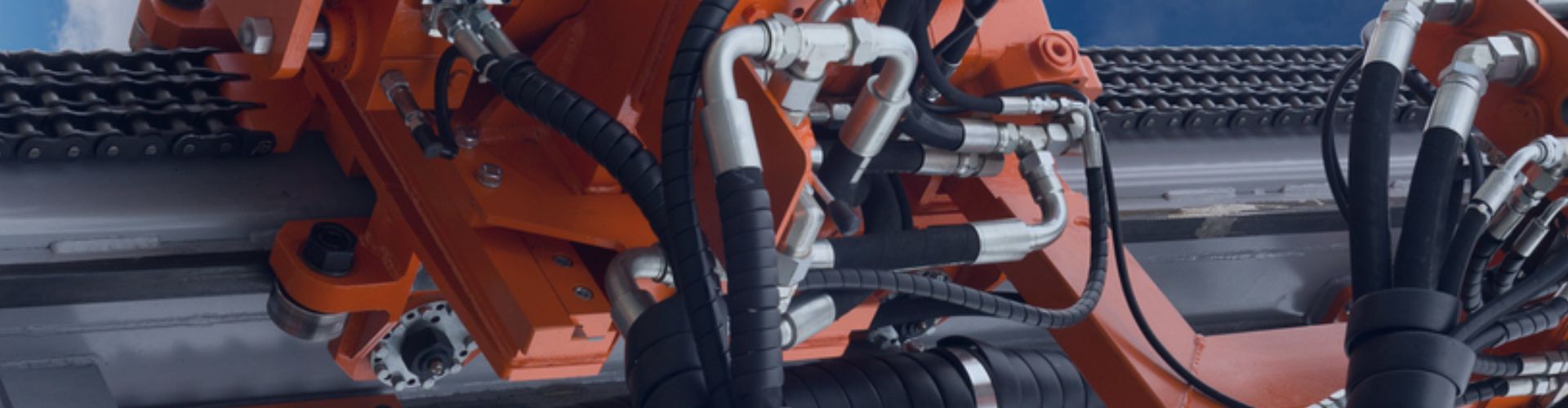
On heavy machinery, hydraulic hoses are vital arteries, yet they
Crafting a reliable hydraulic hose assembly is a science of
A sudden hose failure is more than an inconvenience; it’s
You trust a hydraulic hose with thousands of PSI. A

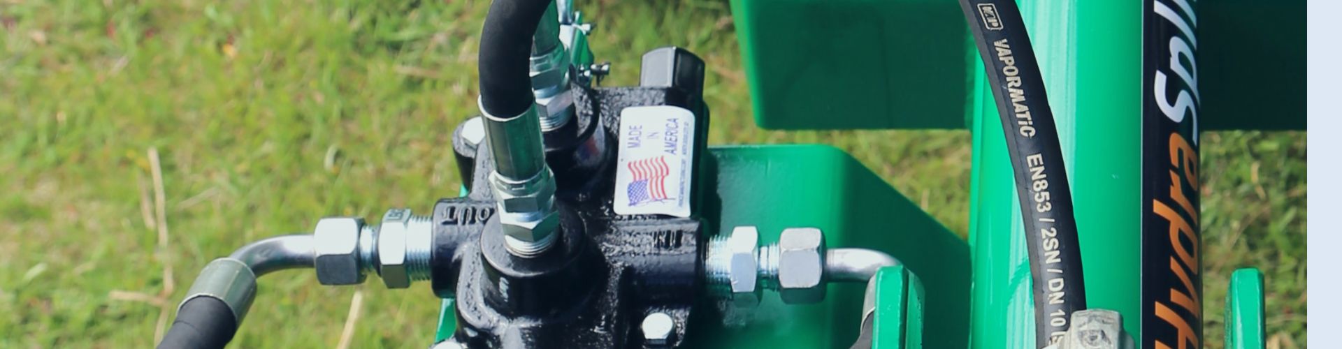
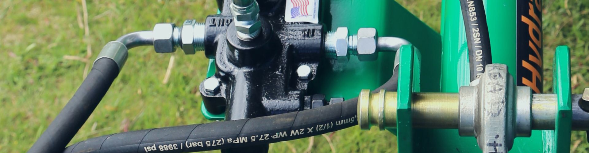
That long line of text printed on a hydraulic hose
Your new hose assembly failed far too soon, causing a
You’re holding a hydraulic fitting with “UNF” threads and need

Your machine is down with a blown hose, miles from