
Why Excavator Boom Hoses Fail and How to Prevent It?
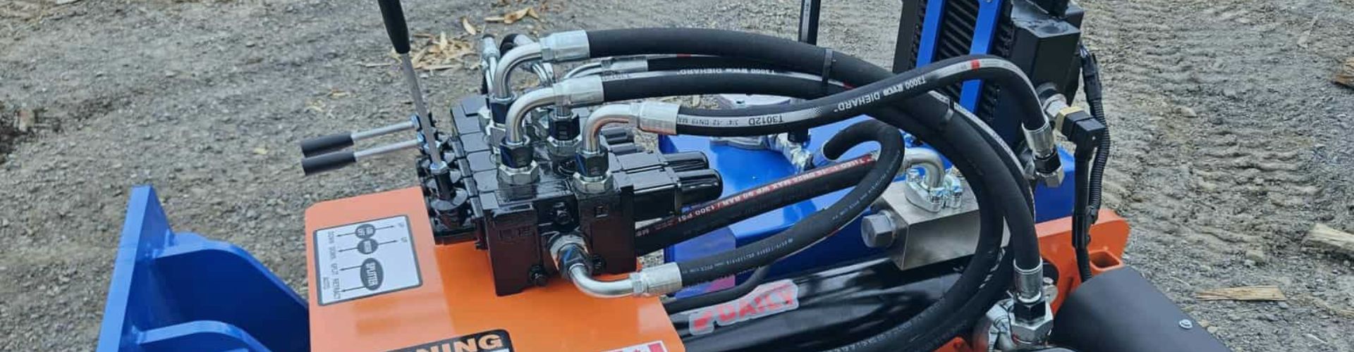
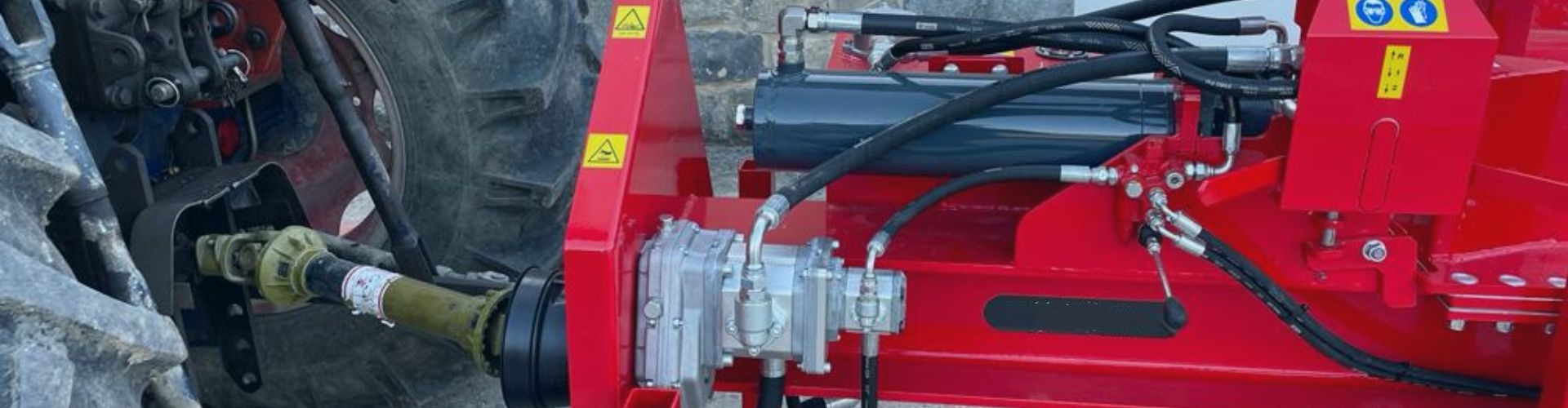
The boom and stick hoses of an excavator are not
The boom and stick hoses of an excavator are not
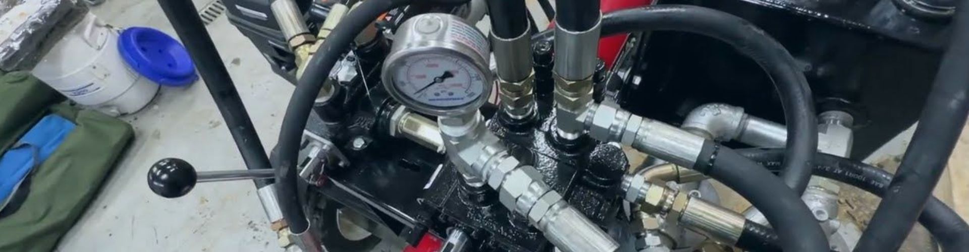
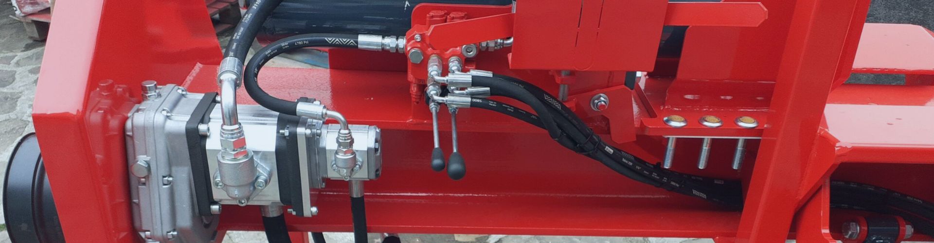
Vibration is the invisible enemy of every hydraulic system. On
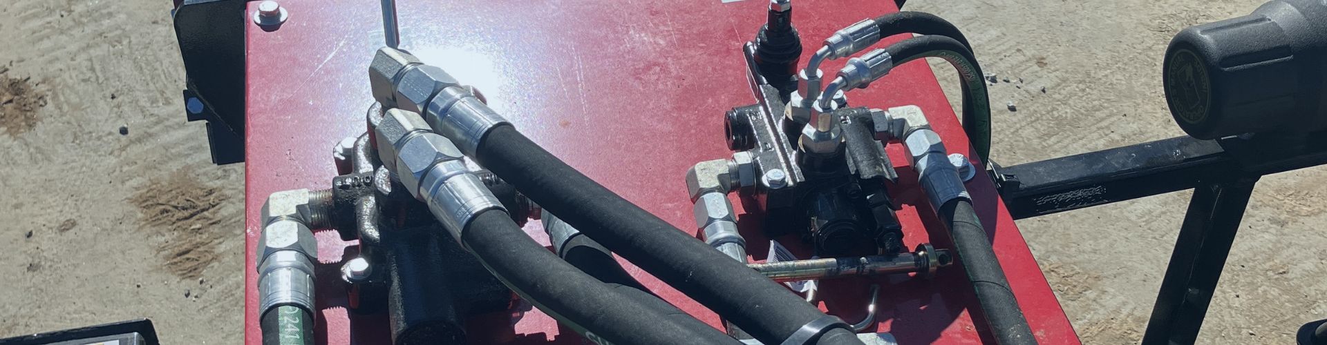
A hose blow-off is a catastrophic event, not a simple
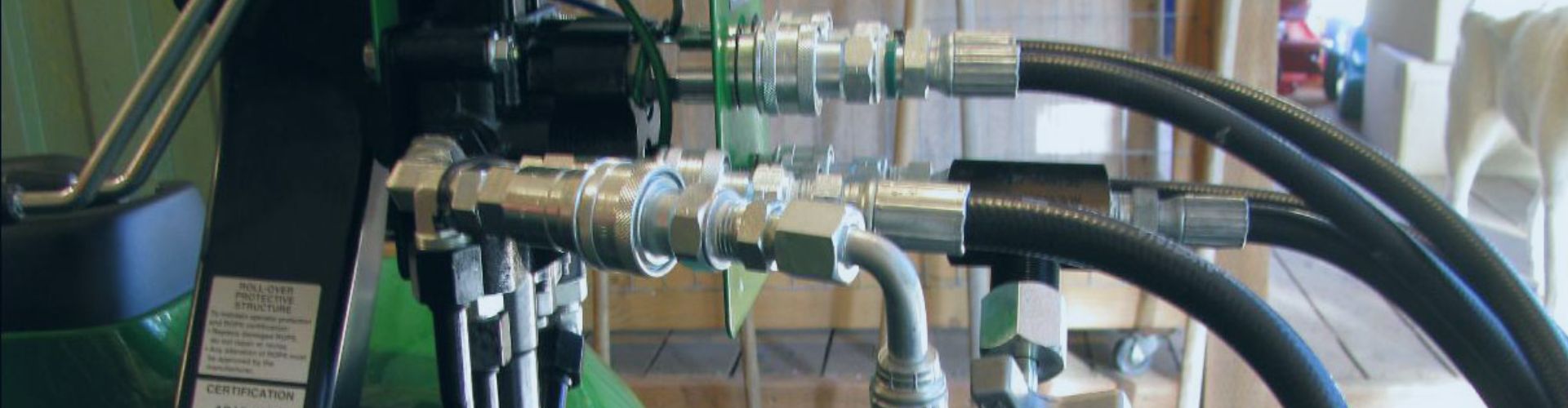
Hydraulic hoses are the veins of an excavator’s power system—every
A recurring hydraulic leak is never just a minor inconvenience—it’s
A hydraulic leak is more than just a maintenance issue—it’s
Replacing hydraulic hoses too early wastes money; too late invites
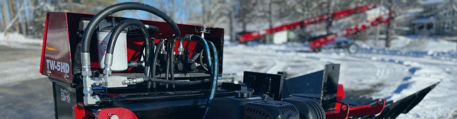
The outer cover of a hydraulic hose is its first

In the controlled calm of a test bench, almost any

Hydraulic hoses inevitably age from heat, oxygen, stress, and ozone,