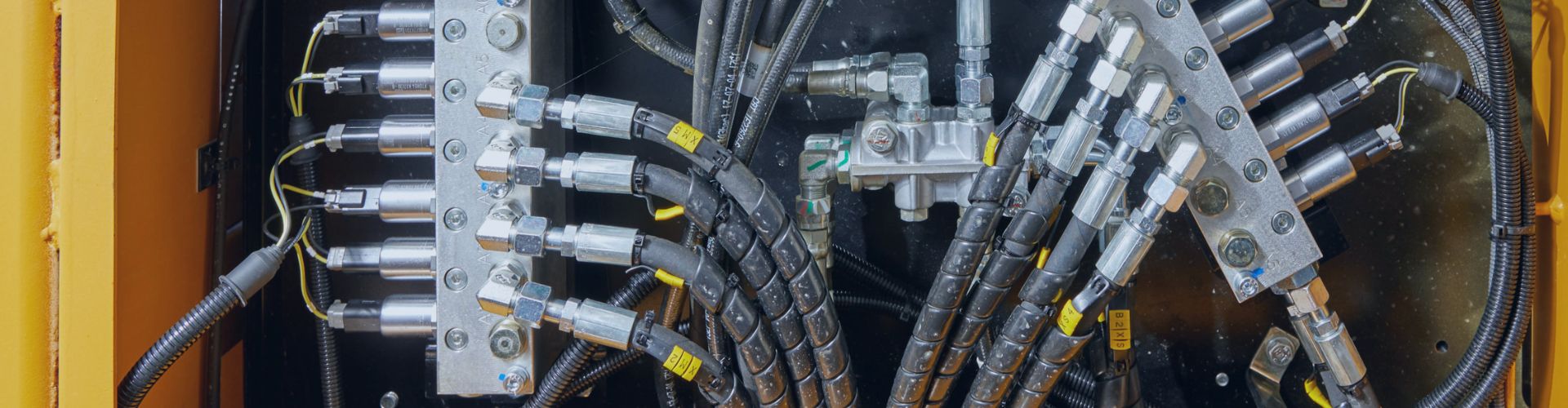
What Information Do Suppliers Need for Custom Hydraulic Hoses?
Machinery downtime can halt your entire production line, leading to
Machinery downtime can halt your entire production line, leading to
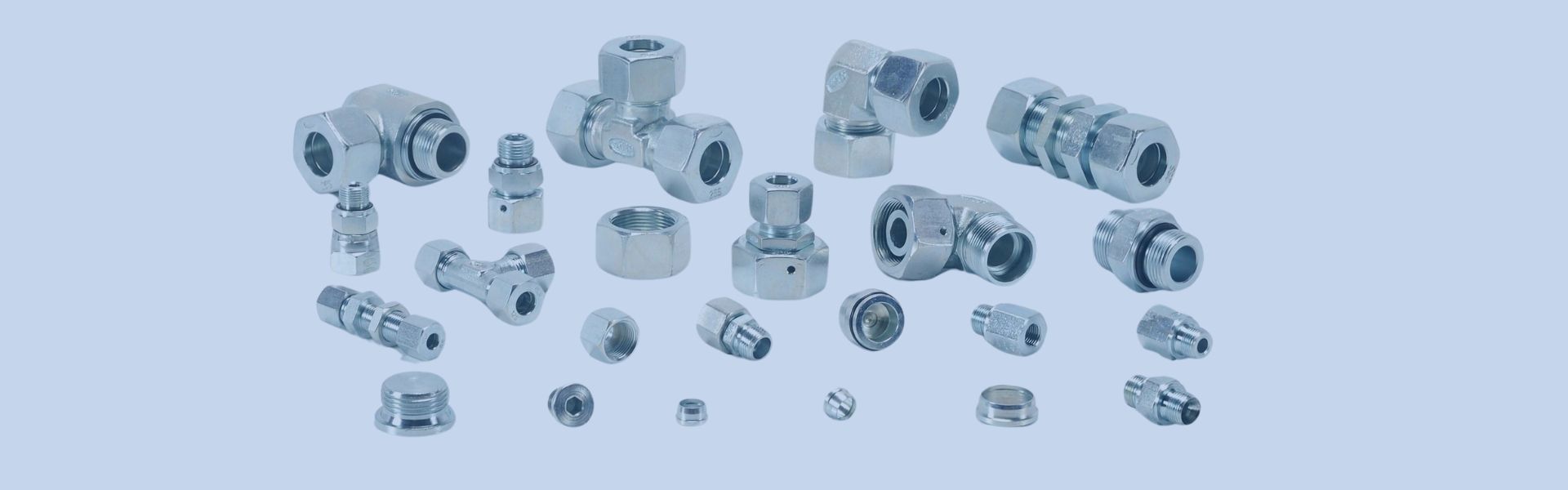
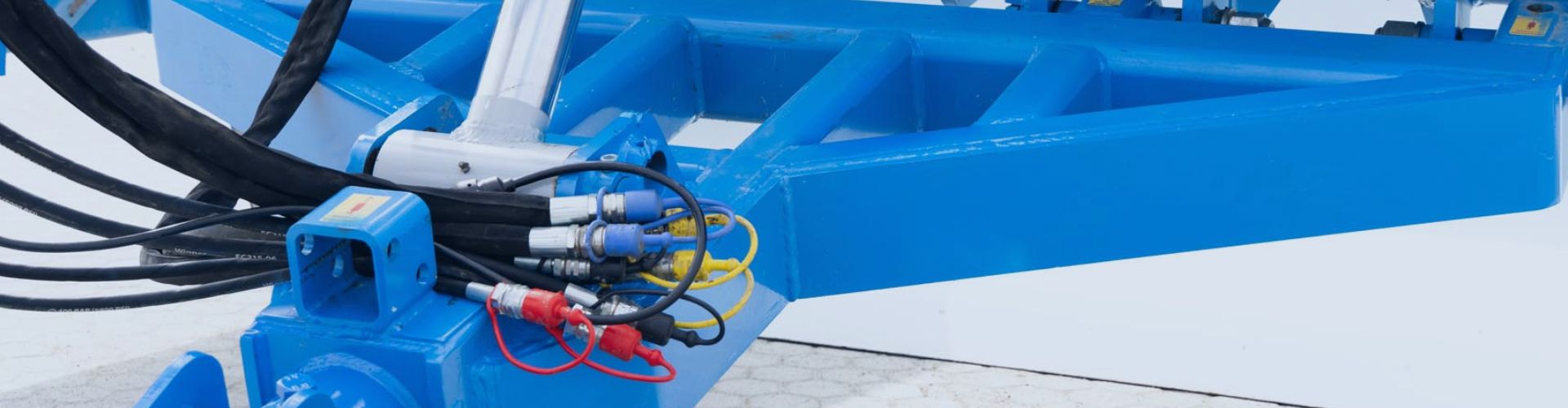
Different types of hydraulic fittings refer to the specialized connectors,
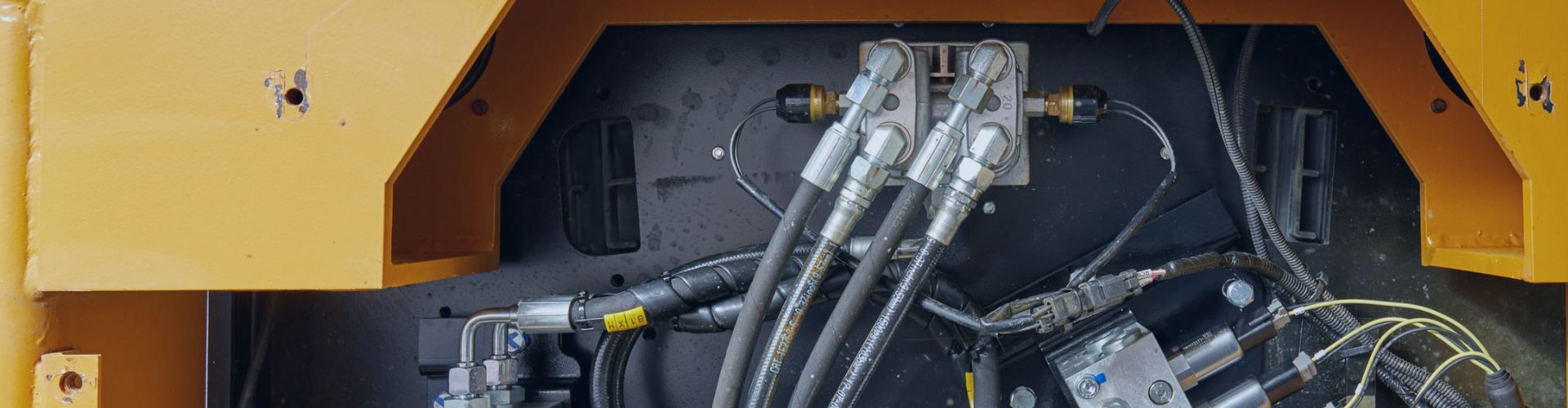
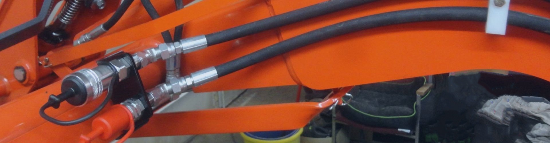
Excavator hydraulic hose failure triggers costly downtime, environmental liability, and
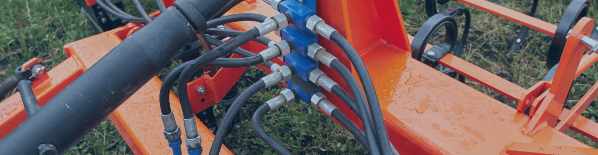
Hydraulic hoses on excavators face constant exposure to mud, dust,
Beyond the Spec Sheet: Simulating the Battlefield A catalog rating—whether
A weeping hose is a failure that has already occurred.
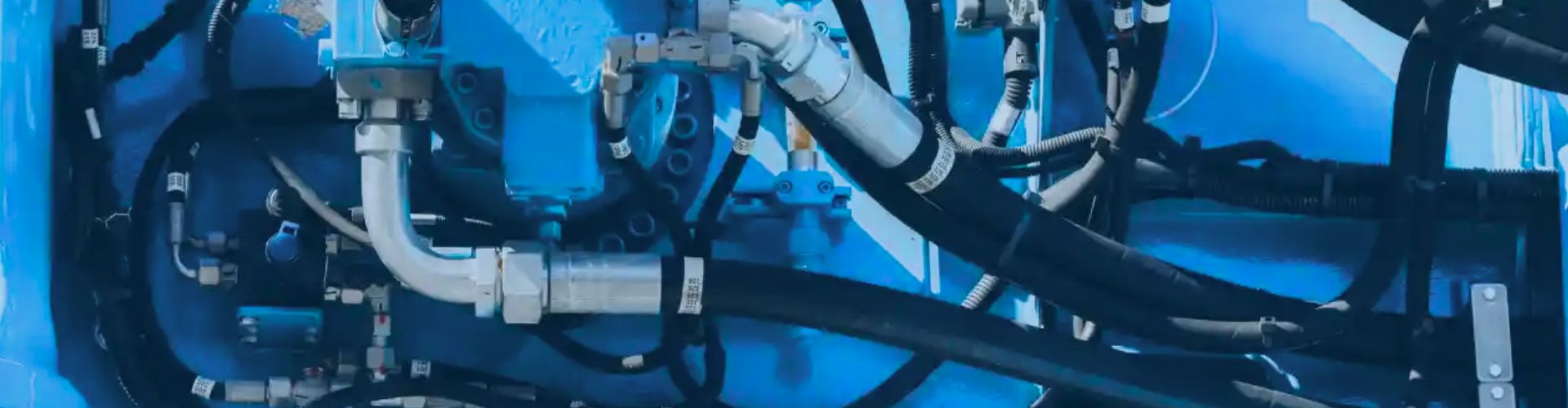
Hydraulic hoses are the lifelines of every excavator. They endure
Pressure loss is wasted fuel and slow performance. This guide
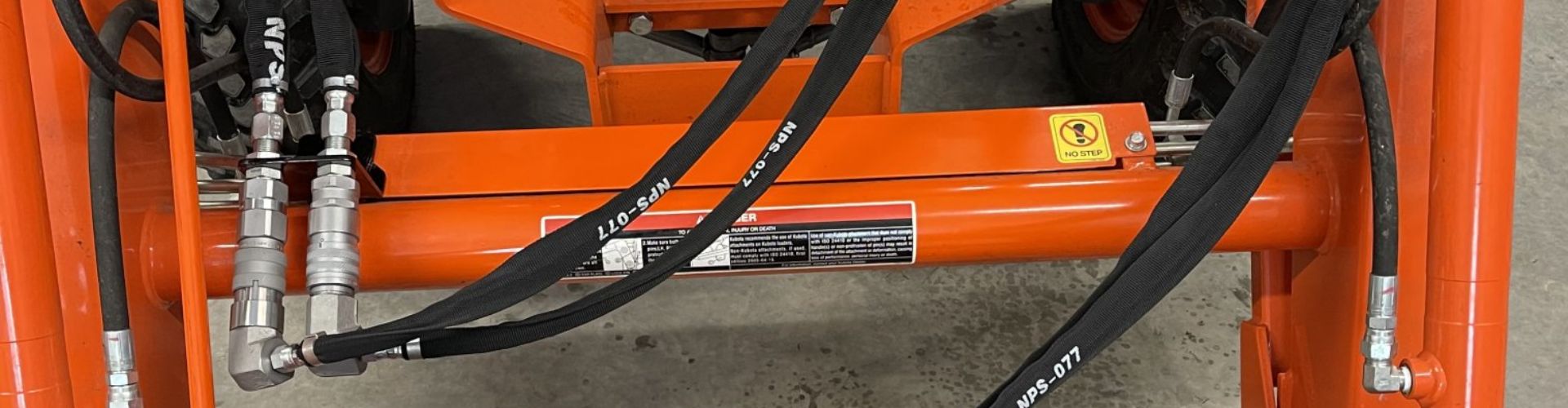
Excavator fittings are engineered for high pressure, not for the
Hydraulic hoses are the lifelines of an excavator’s power system,