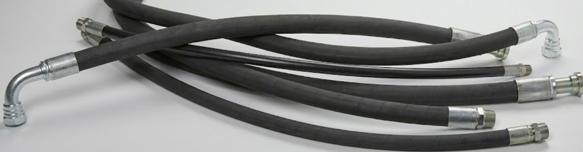
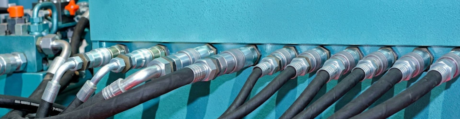
How to Judge High-pressure Hose Quality from Wire Braid Density?
You judge high-pressure hose quality by examining the coverage percentage
You judge high-pressure hose quality by examining the coverage percentage
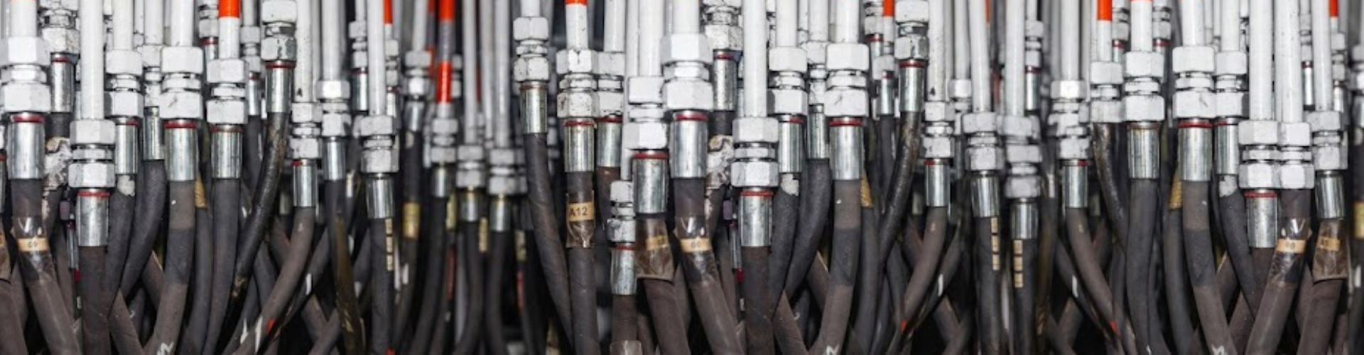
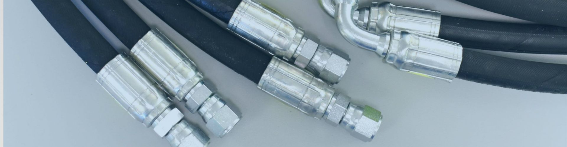
Precision crimping technology that utilizes exact force control and high-quality
A 0.1mm crimping deviation causes serious hydraulic fitting leakage because
Identifying hidden costs in hydraulic fittings requires a deep dive
High replacement frequencies are typically caused by poor maintenance practices,
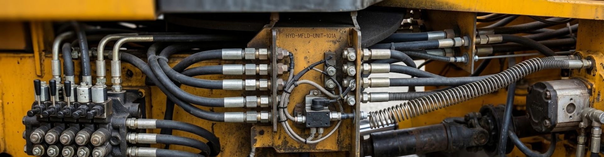
Proper assembly prevents catastrophic leaks, equipment downtime, and workplace injuries

You ensure hydraulic fittings match international standards by verifying certifications
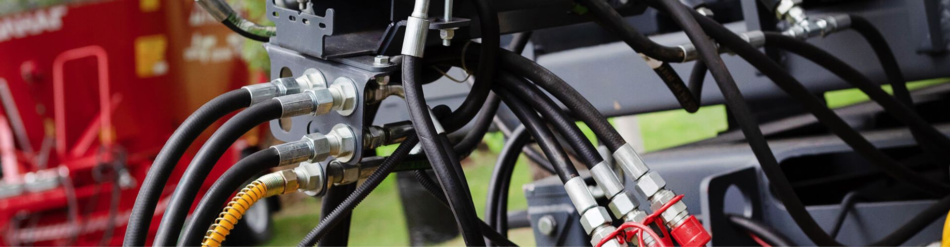
Peak season demands maximum uptime for agricultural operations, yet this
Cheap hydraulic hoses cost more because their lower upfront price
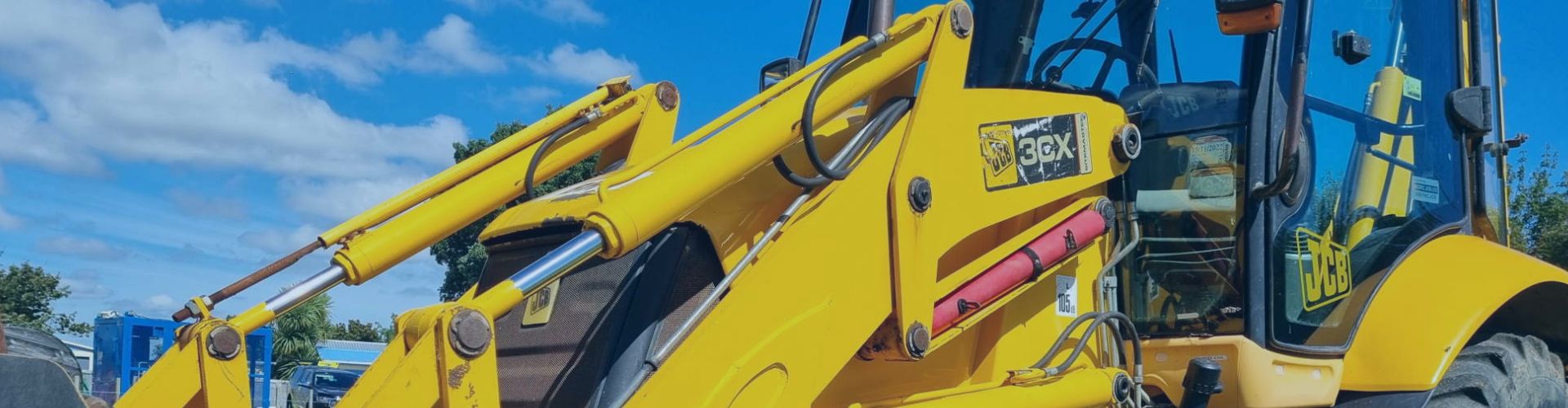
High-pressure braided or spiral hydraulic hoses are best for excavators