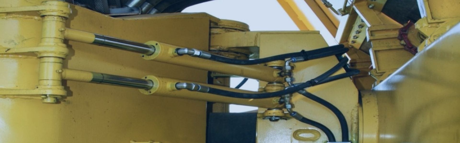
Hydraulic Fluid Contamination banner

Hydraulic Fluid Contamination: Key Prevention Tips

Hydraulic fluid contamination occurs when unwanted substances, such as particles, water, or microorganisms, enter the hydraulic fluid, impairing its performance. Particles can cause abrasive damage, water can degrade lubrication and cause rust, and microorganisms can lead to sludge buildup. Preventing contamination is crucial as it affects system performance, leading to inefficiencies and increased wear. Additionally, contamination results in higher maintenance and repair costs, reduced equipment lifespan, and potential operational downtime, impacting overall productivity and financial outlay.

Types of Hydraulic Fluid Contamination

Hydraulic fitting fluid contamination is a critical issue that can significantly impact the performance and longevity of hydraulic systems. Understanding the different types of contamination, their sources and their effects is essential for maintaining hydraulic system integrity. Here’s a detailed look at the primary types of hydraulic fluids contamination:

Particulate Contamination

Sources:

Wear Particles: These particles originate from the friction between moving parts within hydraulic components. For example, metal particles can be generated from the internal surfaces of pumps, motors, and valves as they operate.

Dirt and Dust: Environmental factors, such as dust storms or industrial environments, can introduce dirt particles into the hydraulic system. Poor sealing or maintenance practices can also allow these contaminants to enter.

Effects:

Abrasion: Abrasive wear caused by particulate contamination can significantly shorten the life of hydraulic components. For instance, if wear particles are present in the hydraulic fluid, they can erode the internal surfaces of pumps, causing performance degradation and potential failure.

Clogging: Over time, particulates can accumulate and block filters, hoses, and valves. This blockage can lead to increased pressure drops, reduced flow rates, and potential overheating of the hydraulic fluid. If filters become too clogged, they can bypass contaminants directly into the system, exacerbating the problem.

Mitigation Strategies:

Filtration: Use high-quality filters and regularly inspect and replace them to prevent particle contamination.

System Maintenance: Implement routine maintenance checks to identify and address sources of wear and potential entry points for external contaminants.

Hydraulic Fluid Contamination

Water Contamination

Sources:

Condensation: In systems where temperature fluctuations are common, water vapor in the air can condense into the hydraulic fluid, especially if the fluid reservoir is not properly sealed.

Leaks: Leaks from seals, gaskets, or joints can allow water from the environment or from other sources to mix with the hydraulic fluid.

Improper Handling: During fluid changes or maintenance, water can be inadvertently introduced if containers or tools are not clean and dry.

Effects:

Corrosion: The presence of water accelerates the corrosion of metal components within the hydraulic system. Rust formation can damage parts like cylinders and pumps, reducing their effectiveness and causing potential failures.

Reduced Lubrication: Water compromises the lubricating properties of hydraulic fluids, leading to increased friction and heat generation. This can result in reduced system efficiency and increased wear on components.

Mitigation Strategies:

Seal Integrity: Regularly check and replace seals and gaskets to prevent leaks.

Water Separation: Use water-absorbing filters or separators designed to remove water from hydraulic fluid.

Chemical Contamination

Sources:

Incompatible Fluids: Mixing hydraulic fluids that have different chemical properties can lead to undesirable reactions. For example, mixing different brands or types of fluids can result in chemical incompatibility.

Additives: Adding incorrect or excessive additives to the hydraulic fluid can alter its chemical balance. This can include adding anti-foaming agents, rust inhibitors, or other chemicals that might not be suitable for the system.

Effects:

Chemical Reactions: These reactions can degrade the hydraulic fluid and damage system components. For instance, some chemical reactions can cause seal materials to swell or deteriorate, leading to leaks.

Degradation: The hydraulic fluid may lose its necessary properties, such as viscosity or lubrication capabilities, due to chemical degradation. This degradation can impact overall system performance and reliability.

Mitigation Strategies:

Fluid Compatibility: Always ensure that hydraulic fluids and additives are compatible with the system’s specifications and with each other.

Monitoring: Regularly test the hydraulic fluid for chemical properties to ensure it remains within the recommended ranges.

Biological Contamination

Sources:

Microorganisms: Bacteria and fungi can thrive in hydraulic fluids, particularly those with high water content or organic compounds. They can enter the system through vents, filters, or during fluid changes.

Algae: Algae can grow in hydraulic fluids, especially if they are exposed to light or stored in warm environments.

Effects:

Growth in Fluids: Biological growth can lead to the formation of sludge and biofilms, which can impair fluid flow and lead to system blockages.

System Fouling: Microbial growth can result in fouling of internal components, such as pumps and valves, reducing their efficiency and potentially leading to failures.

Mitigation Strategies:

Fluid Selection: Use hydraulic fluids with biocides or additives that inhibit microbial growth.

Storage and Handling: Store hydraulic fluids in clean, sealed containers and ensure that the system is properly sealed to prevent microbial contamination.

Understanding and addressing these types of contamination can help maintain the hydraulic system’s efficiency, prevent premature failures, and extend the life of the equipment. Regular monitoring, proper maintenance, and appropriate handling practices are essential to mitigating contamination risks.

Prevention Strategies

Preventing fluid contamination is crucial for maintaining the efficiency and longevity of hydraulic systems. Implementing effective prevention strategies involves regular monitoring, proper filtration, thoughtful system design, diligent fluid handling practices, and thorough maintenance procedures. Here’s an expanded look at each of these prevention strategies:

Regular Monitoring and Testing

Importance of Fluid Analysis:

Early Detection: Regular fluid analysis is essential for identifying contamination and fluid degradation early. By monitoring indicators such as particle count, moisture levels, and chemical composition, potential issues can be addressed before they cause significant damage. Early detection helps in avoiding costly repairs and downtime.

Performance Monitoring: Analyzing hydraulic fluid provides valuable insights into its performance attributes, including lubrication effectiveness, heat transfer capabilities, and corrosion resistance. This information is critical for ensuring that the fluid continues to meet operational requirements and maintain system efficiency.

Decision Making: Fluid analysis data supports informed decision-making regarding fluid changes and system maintenance. It helps determine the optimal timing for fluid replacement, identify the need for additional filtration, and guide adjustments in system operation to maintain peak performance.

Recommended Testing Intervals and Methods:

Testing Intervals: The frequency of fluid testing depends on factors such as the criticality of the system, operating conditions, and the type of fluid used. For high-risk or mission-critical systems, testing should be conducted monthly or quarterly. For less critical applications, testing may be done semi-annually or annually.

Testing Methods:

Visual Inspection: Regularly inspect the hydraulic fluid’s color, clarity, and the presence of particulates. Changes in appearance can indicate contamination or degradation.

Spectrometric Analysis: Use spectrometric methods to measure metal particles in the fluid. This analysis helps assess wear levels and identify the presence of contaminants.

Water Content Analysis: Employ techniques like Karl Fischer titration to accurately measure water content in the hydraulic fluid. High water levels can lead to corrosion and reduced lubrication.

Particle Counting: Utilize laser particle counters to determine the number and size of particles in the fluid. This method helps assess the effectiveness of filtration and identify contamination levels.

Proper Filtration

Types of Filters:

Mechanical Filters: Mechanical filters, including pleated paper filters, mesh screens, and cartridge filters, capture particulate contaminants from the fluid. They are essential for preventing debris from entering sensitive components.

Magnetic Filters: Magnetic filters use magnetic fields to attract and remove ferrous particles from the fluid. These filters are effective in reducing wear and protecting components from damage caused by metal debris.

Electronic Filters: Electronic filters incorporate sensors and control systems to dynamically monitor and adjust filtration processes. They provide real-time feedback on fluid cleanliness and automatically adjust filtering based on contamination levels.

Filter Maintenance and Replacement:

Regular Inspection: Conduct routine inspections of filters to check for clogging, damage, or leaks. Effective filtration is crucial for maintaining fluid purity and system performance.

Replacement Schedule: Follow the manufacturer’s guidelines for filter replacement intervals. Timely replacement prevents bypassing of contaminants and ensures consistent filtration efficiency.

Cleaning Procedures: For reusable filters, implement a cleaning procedure to remove contaminants and restore filter effectiveness. Regular cleaning helps extend the life of the filter and maintains optimal system performance.

Hydraulic Fluid Contamination leak

System Design Considerations

Sealing and Enclosure Designs to Prevent Ingress:

Seals and Gaskets: Use high-quality seals and gaskets that are designed to withstand the operating conditions of the hydraulic system. Regularly inspect and replace seals that show signs of wear or damage to prevent leaks and contamination.

Enclosures: Design enclosures to shield the hydraulic system from environmental contaminants such as dust, dirt, and moisture. Ensure that enclosures are properly sealed and maintained to prevent the ingress of contaminants.

Proper Component Materials and Finishes:

Material Selection: Choose materials for hydraulic components that are resistant to corrosion, wear, and chemical reactions. This reduces the likelihood of contamination and extends the life of the components.

Finishes: Apply protective coatings and finishes to hydraulic components to enhance their resistance to wear and environmental factors. Regularly inspect and maintain these finishes to prevent deterioration and protect the underlying materials.

Fluid Handling Practices

Clean Handling and Storage Procedures:

Handling: Utilize clean equipment and containers for transferring hydraulic fluid. Prevent contamination by ensuring that all handling practices minimize exposure to dirt, dust, and other potential contaminants.

Storage: Store hydraulic fluids in clean, sealed containers to prevent contamination from external sources. Maintain storage areas free from dust, moisture, and other contaminants that could compromise the fluid quality.

Avoiding Cross-Contamination with Other Fluids:

Separate Storage: Store different types of hydraulic fluids separately to avoid accidental mixing. Clearly label containers to indicate the type of fluid they contain and prevent cross-contamination.

Dedicated Equipment: Use dedicated equipment for handling and transferring hydraulic fluids to avoid cross-contamination. Thoroughly clean equipment between uses to ensure that contaminants from previous fluids do not affect new fluids.

Maintenance Procedures

Regular System Inspections and Maintenance Routines:

Inspection Schedule: Implement a regular inspection schedule to assess the hydraulic system for signs of contamination, wear, and other issues. Include checks for fluid condition, filter status, and the integrity of components.

Maintenance Tasks: Perform routine maintenance tasks such as changing filters, cleaning components, and replacing worn parts according to a preventive maintenance plan. Address issues proactively to prevent system failures and ensure continued reliability.

Procedures for Handling Leaks and Spills:

Leak Detection: Install systems for early leak detection, such as pressure sensors or visual inspection protocols. Promptly address leaks to prevent contamination and damage to the hydraulic system.

Spill Response: Develop and implement procedures for effectively cleaning up spills. Use appropriate absorbent materials and follow proper disposal methods for contaminated fluids. Ensure that spill response equipment is readily available and that staff are trained to handle spills efficiently.

Best Practices for Fluid Management

Training and Awareness

Educating Staff on Contamination Risks and Prevention:

Contamination Awareness: Train employees on the types of contamination, their sources, and the potential effects on hydraulic systems. Understanding these aspects helps in recognizing and mitigating risks.

Prevention Techniques: Provide training on proper fluid handling, filtration, and maintenance procedures to minimize contamination. Ensure staff are familiar with best practices for maintaining system cleanliness.

Safety Protocols: Educate staff on safety protocols related to fluid handling, including the use of personal protective equipment (PPE) and safe work practices to prevent accidental exposure or spills.

Documentation and Records

Keeping Detailed Records of Fluid Condition and Maintenance:

Fluid Analysis Records: Maintain comprehensive records of fluid analysis results, including test dates, findings, and any corrective actions taken. This helps in tracking trends and making informed decisions about fluid management.

Maintenance Logs: Document all maintenance activities, including filter changes, seal replacements, and system inspections. Include details on the frequency of maintenance and any issues encountered.

Incident Reports: Keep records of any contamination incidents, including the causes, responses, and outcomes. Analyzing these reports can help in improving prevention strategies and response procedures.

Emergency Response

Procedures for Dealing with Contamination Incidents:

Immediate Actions: Develop and implement procedures for immediate response to contamination incidents, such as isolating the affected area, stopping fluid flow, and containing spills. Quick action helps minimize damage and prevent further contamination.

Containment and Cleanup: Use appropriate containment materials and techniques to control and clean up spills. Follow established protocols for disposing of contaminated fluids and materials by environmental regulations.

Root Cause Analysis: After addressing the immediate incident, conduct a root cause analysis to determine how the contamination occurred. Identify any system or procedural weaknesses that contributed to the incident and implement corrective measures to prevent recurrence.

Communication: Ensure clear communication with all relevant stakeholders during and after an incident. Provide updates on the situation, actions taken, and any changes to procedures or policies as needed.

Conclusion

Actively applying these prevention strategies will significantly reduce the risk of fluid contamination and enhance system reliability. Regularly review and update your contamination control measures to adapt to evolving operational conditions and technological advancements. By prioritizing these practices, you ensure the longevity and optimal performance of your hydraulic systems.


FAQ

What is hydraulic fluids contamination?

Hydraulic fluids contamination occurs when unwanted substances, such as particles, water, chemicals, or microorganisms, enter the hydraulic fluid, affecting system performance and longevity.

How can I prevent particulate contamination in hydraulic systems?

Prevent particulate contamination by using high-quality filters, regularly inspecting and maintaining them, and ensuring clean handling and storage of hydraulic fluids.

What are the common sources of water contamination in hydraulic fluids?

Common sources include condensation due to temperature fluctuations, leaks from seals and gaskets, and improper handling during fluid changes.

What are the effects of chemical contamination on hydraulic systems?

Chemical contamination can lead to adverse reactions between fluids or additives, causing fluid degradation and potential damage to system components.

How can I identify biological contamination in hydraulic fluids?

Signs of biological contamination include unusual odors, visible sludge or biomass, and reduced fluid performance. Regular fluid analysis can help detect microbial growth.

What should I do if a contamination incident occurs?

Immediately contain and clean up the spill, stop the fluid flow if possible, and follow established procedures for disposal. Perform a root cause analysis to prevent future occurrences.

Hydraulic Fluid Characteristics banner

Hydraulic Fluid Characteristics: What You Need to Know

Hydraulic fluids are crucial in hydraulic systems, enabling machinery and equipment to operate efficiently by transmitting force through pressure and flow. Understanding these fluids is essential because it affects system performance, component longevity, safety, and cost efficiency. Key characteristics to be explored include the types of fluids, their properties, performance factors, and best practices for selection and maintenance. This knowledge ensures effective management and optimal operation of hydraulic systems.

Types of Hydraulic Fluids

Mineral Oils

Mineral oils are the most prevalent type of hydraulic fluid, primarily due to their cost-effectiveness and established performance characteristics. These fitting fluids are derived from the refining of crude oil and have been used in hydraulic systems for decades. Their composition generally includes a base oil with various additives to enhance performance.

Advantages:

Good Lubrication Properties: Mineral oils provide effective lubrication, which reduces friction and wear on hydraulic components.

Broad Applicability: They are versatile and can be used in a wide range of hydraulic systems and applications.

Cost-Effectiveness: Mineral oils are generally less expensive than specialized hydraulic fluids, making them a popular choice for many applications.

Disadvantages:

Limited Fire Resistance: Mineral oils are flammable and can pose a fire hazard in high-temperature environments or in applications where sparks or open flames are present.

Potential Environmental Hazards: When spilled or improperly disposed of, mineral oils can cause environmental contamination. Their disposal often requires special handling procedures to minimize ecological impact.

hydraulic fluid Topa

Water-Based Fluids

Water-based fluids are designed to offer improved fire resistance compared to mineral oils, making them suitable for applications where fire risk is a concern. These fluids come in several types, including water-glycol solutions and water-oil emulsions.

Water-Glycol Solutions: Water-glycol solutions consist of a mixture of water and glycol. They offer significant fire resistance due to the high water content. However, they have some limitations in performance.

Benefits:

Enhanced Fire Safety: The high water content provides excellent fire resistance, reducing the risk of fire in high-temperature environments.

Reduced Flammability: The presence of water makes these fluids less flammable compared to pure mineral oils.

Limitations:

Lower Lubrication Properties: Water-glycol solutions generally have poorer lubrication properties compared to mineral oils, which can affect the efficiency and lifespan of hydraulic components.

Corrosion Risk: The water content can lead to corrosion of metal components if not properly managed, necessitating the use of corrosion inhibitors.

Water-Oil Emulsions: Water-oil emulsions are mixtures of water and oil, with the water content varying depending on the required fire resistance level.

Benefits:

Fire Resistance: Like water-glycol solutions, these emulsions offer improved fire resistance compared to mineral oils.

Customizable: The ratio of water to oil can be adjusted to balance fire resistance with lubrication properties.

Limitations:

Corrosion Issues: Similar to water-glycol solutions, water-oil emulsions can lead to corrosion if proper maintenance and corrosion inhibitors are not used.

Reduced Lubrication: The lubrication properties of water-oil emulsions can be inferior to those of pure mineral oils.

Fire-Resistant Fluids

Fire-resistant fluids are essential in industries where there is a high risk of fire, such as steel mills, aerospace, and other high-temperature environments. These fluids are designed to resist ignition and burning, providing enhanced safety in critical applications.

Phosphate Esters: Phosphate esters are a type of fire-resistant fluid known for their excellent fire resistance properties.

Benefits:

Superior Fire Resistance: Phosphate esters are highly resistant to ignition and burning, making them suitable for extremely hazardous environments.

High Thermal Stability: They maintain performance at high temperatures, which is critical in industries like steel manufacturing.

Disadvantages:

Cost: Phosphate esters can be more expensive than mineral oils and other hydraulic fluids.

Handling Requirements: They require special handling and storage procedures to ensure safety and prevent degradation.

Organic Esters: Organic esters are another category of fire-resistant fluids, known for their lower flammability and environmental benefits.

Benefits:

Reduced Flammability: Organic esters have a lower risk of catching fire compared to mineral oils, making them suitable for various high-risk environments.

Environmental Benefits: They are often biodegradable and have a lower environmental impact compared to traditional mineral oils.

Disadvantages:

Higher Cost: Organic esters can be more costly than other types of hydraulic fluids.

Compatibility Issues: They may not be compatible with all materials used in hydraulic systems, necessitating careful selection of system components.

Key Properties of Hydraulic Fluids

Viscosity

Viscosity is a measure of a fluid’s resistance to flow, which plays a crucial role in hydraulic systems. It determines how easily the fluid can move through the system’s components.

Definition and Significance: Viscosity is defined as the internal friction within a fluid that resists flow. It is a key parameter in ensuring the hydraulic fluid performs optimally.

Impact on System Performance: Proper viscosity ensures that the fluid flows smoothly through the system, maintaining a consistent flow rate and pressure. Fluids with appropriate viscosity contribute to efficient energy use and system stability. If the viscosity is too high, it can lead to increased energy consumption and reduced efficiency. Conversely, too low viscosity may result in inadequate lubrication and potential system wear.

Compressibility

Compressibility refers to the extent to which a fluid’s volume decreases under pressure. It is essential for the proper operation of hydraulic systems, particularly in applications requiring precise control.

Importance in Hydraulic System Operation: Compressibility affects how the fluid responds to pressure changes. Fluids with low compressibility maintain more stable volume and pressure under varying conditions, which is critical for accurate control and system response.

Effects on System Response and Stability: A fluid with low compressibility ensures minimal changes in volume, providing stable and predictable performance. High compressibility can lead to system instability and delayed responses, impacting the overall effectiveness of hydraulic operations.

Hydraulic Fluid Characteristics

Lubricating Properties

Hydraulic fluids must possess adequate lubricating properties to ensure the longevity and efficient operation of system components.

Role in Reducing Wear and Tear: Proper lubrication minimizes friction between moving parts, reducing wear and extending the lifespan of components. Effective lubrication is essential for preventing premature component failure and maintaining system performance.

Impact on Component Lifespan: Well-lubricated components experience less friction and heat generation, which translates to longer service life and reduced maintenance requirements. This contributes to overall system reliability and cost-effectiveness.

Thermal Stability

Thermal stability is the ability of a hydraulic fluid to resist degradation and maintain performance at elevated temperatures.

Ability to Withstand Temperature Variations: Fluids with high thermal stability can endure high operating temperatures without breaking down or losing their effectiveness. This is crucial for systems exposed to fluctuating or extreme temperatures.

Effects on Fluid Degradation and System Reliability: High thermal stability prevents fluid breakdown and degradation, ensuring consistent performance and protecting the hydraulic system from potential failures caused by overheating or thermal stress.

Chemical Stability

Chemical stability involves a fluid’s resistance to chemical changes such as oxidation and contamination, which can impact its performance and longevity.

Resistance to Oxidation and Contamination: A chemically stable fluid resists oxidation and other chemical reactions that can lead to the formation of harmful by-products. This stability helps maintain fluid integrity and system health.

Impact on Fluid Life and System Health: Chemically stable fluids have a longer service life and reduce the risk of clogging, corrosion, and other issues that can compromise system performance. Proper chemical stability is essential for maintaining overall fluid quality and system reliability.

Performance Characteristics

Pumpability

Pumpability measures how effectively a hydraulic fluid can be moved through the system by the pump. This characteristic is crucial for ensuring smooth operation and optimal energy consumption.

Definition and Importance: Pumpability refers to the ease with which a fluid is transported through the hydraulic system. It affects the efficiency of the pump and overall system performance.

Impact on System Operation: Fluids with poor pumpability can lead to increased friction and strain on the pump, causing potential wear and operational issues. Ensuring high pumpability helps maintain consistent flow, reduce energy consumption, and prevent damage to system components.

Anti-Wear Properties

Anti-wear properties are essential for protecting hydraulic system components from damage caused by friction and mechanical wear.

Mechanisms to Protect System Components: Hydraulic fluids often contain additives specifically designed to enhance anti-wear properties. These additives form a protective film on metal surfaces, reducing friction and wear.

Ensuring Longevity and Reliability: Effective anti-wear properties extend the lifespan of hydraulic components by minimizing damage and reducing the frequency of maintenance. This contributes to the overall reliability and efficiency of the hydraulic system.

Corrosion Resistance

Corrosion resistance is the ability of hydraulic fluid to protect metal surfaces from corrosive damage caused by chemical reactions.

Role in Protecting Metal Surfaces: Hydraulic fluids with good corrosion resistance prevent the formation of rust and other corrosive compounds that can damage metal components. This protection is crucial for maintaining system integrity and preventing leaks or component failures.

Extending Component Life: By protecting against corrosion, a fluid helps extend the lifespan of metal parts and ensures consistent performance over time. This reduces the need for frequent replacements and repairs, enhancing the overall cost-effectiveness of the system.

Topa Hydraulic Fluid Characteristics

Foaming and Air Release

Foaming and air release characteristics impact the efficiency and safety of hydraulic systems.

Effects on System Efficiency: Foaming can lead to cavitation, where air bubbles collapse violently, causing damage to components and reducing performance. Effective hydraulic fluids should minimize foaming and facilitate rapid air release to maintain system efficiency.

Impact on Safety and Performance: Properly formulated fluids reduce the likelihood of cavitation and ensure that trapped air is quickly released, which helps maintain stable operation and prevents potential hazards associated with air bubbles in the system.

Selecting the Right Hydraulic Fluid

Application Considerations

Choosing the appropriate hydraulic fluid requires aligning its properties with the specific needs of the hydraulic system.

Operating Temperature: Select a fluid that remains stable and maintains performance across the expected temperature range of the system. Fluids with high thermal stability are essential for systems that operate under varying or extreme temperatures.

Pressure Requirements: Ensure the fluid can handle the maximum operating pressure of the system without degrading or causing issues. Fluids with suitable compressibility characteristics are crucial for maintaining system stability and performance under high pressure.

Fire or Environmental Hazards: For applications with high fire risks, such as in steel mills or aerospace, select fluids with high fire resistance. Consider environmental factors if the system operates in sensitive areas, opting for fluids that minimize ecological impact or contamination.

Environmental and Safety Factors

Selecting hydraulic fluids based on their environmental impact and safety features is crucial for responsible operation and compliance with regulations.

Biodegradability: Opt for biodegradable fluids if there is a risk of spillage or leakage into the environment. Biodegradable fluids break down more quickly and reduce long-term environmental damage.

Toxicity: Consider the toxicity of the hydraulic fluid, especially if the system is used in environments where human exposure is possible. Non-toxic fluids are safer and more environmentally friendly, reducing health risks.

Flammability: Choose fluids with appropriate flammability characteristics based on the system’s operating environment. For high-risk areas, select fluids with lower flammability to enhance safety and reduce fire hazards.

Manufacturer Recommendations

Following manufacturer recommendations is essential for ensuring the hydraulic system operates efficiently and reliably.

Adherence to Recommended Fluids: Manufacturers often provide specific fluid recommendations based on system design and component materials. Using the recommended fluid helps maintain optimal performance and avoid issues related to incompatibility or degradation.

Maintenance Practices: Along with selecting the right fluid, adhering to recommended maintenance practices is crucial. This includes regular monitoring of fluid condition, timely replacement, and proper handling procedures. Following these guidelines helps extend the system’s lifespan and ensures ongoing reliability and efficiency.

Maintenance and Management

Monitoring Fluid Quality

Regular monitoring of hydraulic fluid quality is essential for maintaining optimal system performance and preventing issues.

Methods for Assessing Fluid Condition: Regular assessments include visual inspections, where operators check for changes in color, clarity, or the presence of contaminants. Analytical tests, such as viscosity measurements, particle counts, and chemical analyses, provide detailed insights into fluid conditions.

Benefits of Monitoring: Early detection of issues like degradation, contamination, or reduced performance allows for timely interventions. Consistent monitoring helps maintain system efficiency, extend component lifespan, and prevent costly breakdowns.

Fluid Replacement and Disposal

Proper fluid replacement and disposal practices are critical for system maintenance and environmental protection.

Fluid Replacement Guidelines: Replace hydraulic fluids based on manufacturer recommendations or when analysis indicates significant degradation. Follow recommended intervals or triggers such as changes in fluid properties or system performance issues.

Best Practices for Disposal: Ensure proper disposal of used hydraulic fluids according to local regulations and environmental guidelines. Many regions have specific requirements for the handling and disposal of hazardous materials to minimize environmental impact. Employ recycling or waste management services that comply with these regulations.

Handling Contamination

Contamination can severely impact hydraulic system performance and longevity, so effective management strategies are crucial.

Prevention Through Filtration: Implement proper filtration systems to remove contaminants such as particles, water, and debris from the hydraulic fluid. Regularly replace filters and ensure they are appropriately sized for the system.

Handling Contamination Incidents: Develop and follow protocols for responding to contamination events. This includes immediate isolation of affected areas, system cleaning, and fluid replacement. Addressing contamination quickly helps prevent damage and ensures continued system reliability.

Regular System Checks: Conduct routine inspections and maintenance to identify potential sources of contamination. Regular checks help maintain fluid quality and system performance, reducing the risk of operational issues.

Conclusion

Performance characteristics such as pumpability, anti-wear properties, corrosion resistance, and foaming and air release further influence system effectiveness and longevity. Making informed decisions based on these factors, as well as adhering to best practices for fluid maintenance and management, ensures that your hydraulic systems operate reliably and efficiently. Regular monitoring, proper fluid replacement, and effective contamination handling are essential to maintain fluid quality and system performance.


FAQ

What are the main types of hydraulic fluids?

The main types of hydraulic fluids include mineral oils, water-based fluids (such as water-glycol solutions and water-oil emulsions), and fire-resistant fluids (like phosphate esters and organic esters). Each type has specific applications and properties suited to different operational needs.

How does viscosity affect hydraulic fluid performance?

Viscosity measures a fluid’s resistance to flow. It affects how easily the fluid moves through the system and maintains pressure. Proper viscosity ensures smooth operation, energy efficiency, and stable system performance.

Why is thermal stability important for hydraulic fluids?

Thermal stability indicates a fluid’s ability to withstand high temperatures without degrading. It is crucial for maintaining consistent performance and preventing fluid breakdown, which can lead to system failure and reduced reliability.

How can I monitor the quality of hydraulic fluid?

You can monitor hydraulic fluid quality through visual inspections for changes in color or clarity and analytical tests that measure properties like viscosity and contamination levels. Regular checks help detect issues early and maintain system performance.

What should I consider when selecting hydraulic fluid for my system?

Consider factors such as the operating temperature and pressure of your system, fire or environmental hazards, and the fluid’s compatibility with system components. It’s also important to follow manufacturer recommendations for optimal performance.

How should I handle the disposal of used hydraulic fluids?

Dispose of used hydraulic fluids according to local regulations and environmental guidelines. Many areas have specific rules for the disposal of hazardous materials.

Different Hose Clamps banner

Different Hose Clamps: How to Tighten or Remove

Hose clamps are essential components used to secure hoses onto fittings or pipes, ensuring a leak-proof connection in various systems, from automotive to industrial applications. Proper tightening and removal of hose clamps are crucial to maintain system integrity, prevent leaks, and avoid damage to the hoses. This post aims to provide a comprehensive guide on the different types of hose clamps, how to correctly tighten and remove them, and best practices to ensure reliable performance and longevity.

Types of Hose Clamps

A. Worm Gear Clamps

Description: Worm gear clamps consist of a metal band with a screw mechanism that tightens the band around the hose. They are often made of stainless steel for corrosion resistance.

Common Uses: Used in automotive, plumbing, and industrial applications where adjustable and secure fastening is needed.

Advantages:

Adjustable size for a range of hose diameters.

Provides a strong and secure hold.

Widely available and relatively inexpensive.

Disadvantages:

Can damage the hose if over-tightened.

May be susceptible to corrosion if not made from stainless steel.

Requires a screwdriver for adjustment.

worm gear hose clamp factory

B. Spring Clamps

Description: Spring clamps use a spring mechanism to exert constant pressure on the hose. They are usually made from stainless steel or spring steel.

Common Uses: Common in automotive and household applications where consistent pressure is required without frequent adjustments.

Advantages:

No tools are needed for adjustment.

Maintains consistent pressure on the hose.

Durable and resistant to corrosion.

Disadvantages:

Limited to specific hose sizes.

Can be difficult to install or remove in tight spaces.

Less flexible in terms of size adjustments compared to worm gear clamps.

C. T-Bolt Clamps

Description: T-bolt clamps have a band with a T-bolt mechanism that provides high clamping force. They are usually made from stainless steel and are designed for heavy-duty applications.

Common Uses: Used in high-pressure applications, including in automotive and industrial systems where a strong, leak-proof seal is required.

Advantages:

Provides a strong and secure hold, suitable for high-pressure applications.

Adjustable and can accommodate a range of hose sizes.

Resistant to vibration and movement.

Disadvantages:

Generally more expensive than other types of clamps.

Requires a wrench or socket for adjustment.

Larger and heavier, which may not be suitable for all applications.

single ear hose clamp supplier

D. Ear Clamps

Description: Ear clamps are a type of clamp where the band is formed into an “ear” shape that is crimped onto the hose. They are typically used for their simplicity and effectiveness.

Common Uses: Often used in automotive and industrial applications where a tight, permanent seal is needed.

Advantages:

Provides a tight, permanent seal that is resistant to leakage.

Simple in design and easy to use with crimping tools.

Affordable and reliable for specific applications.

Disadvantages:

Not adjustable once installed, so exact sizing is critical.

Requires specialized tools for installation and removal.

Can be challenging to install or remove in confined spaces.

E. Band Clamps

Description: Band clamps are similar to worm gear clamps but often feature a wider band for distributing pressure more evenly. They are used in a variety of applications and can be made from different materials including stainless steel.

Common Uses: Used in both automotive and industrial settings, particularly where a more even distribution of pressure is required.

Advantages:

Provides an even clamping force, reducing the risk of hose damage.

Adjustable and suitable for various hose sizes.

Durable and resistant to high pressures.

Disadvantages:

Can be more expensive than standard worm gear clamps.

Requires a tool for adjustment.

Bulkier than some other types of clamps, which may limit use in tight spaces.

How to Tighten Hose Clamps

A. Worm Gear Clamps

Step-by-Step Instructions:

Position the Clamp: Slide the clamp over the hose and align it with the fitting.

Adjust the Size: Use a screwdriver to turn the screw on the clamp, adjusting the size to fit the hose snugly.

Tighten the Clamp: Turn the screw clockwise to tighten the clamp around the hose and fitting.

Check for Tightness: Ensure the clamp is tight but not over-tightened, which can damage the hose.

Tips for Proper Tightening:

Use a screwdriver with a good grip to avoid slipping.

Check the clamp periodically to ensure it maintains the correct tightness.

Avoid over-tightening to prevent crushing or deforming the hose.

B. Spring Clamps

Step-by-Step Instructions:

Position the Clamp: Place the spring clamp around the hose and fitting.

Compress the Spring: Use pliers to compress the spring and slide the clamp into position.

Release the Clamp: Let go of the pliers to allow the spring clamp to expand and secure the hose.

Verify the Fit: Check that the clamp is securely in place and providing even pressure.

Tips for Proper Tightening:

Use pliers with a firm grip to control the spring clamp.

Ensure the clamp is positioned evenly around the hose to prevent leaks.

Avoid using excessive force when compressing the spring to prevent damage.

Hose Clamp application

C. T-Bolt Clamps

Step-by-Step Instructions:

Position the Clamp: Place the T-bolt clamp around the hose and fitting.

Align the Bolt: Ensure the T-bolt is aligned with the clamp’s slots.

Tighten the Bolt: Use a wrench or socket to turn the T-bolt clockwise, tightening the clamp around the hose.

Check for Tightness: Confirm that the clamp is securely tightened without any movement.

Tips for Proper Tightening:

Use a torque wrench to ensure even tightening and prevent over-tightening.

Make sure the clamp is properly aligned to avoid uneven pressure.

Regularly inspect the clamp for any signs of wear or loosening.

D. Ear Clamps

Step-by-Step Instructions:

Position the Clamp: Slide the ear clamp over the hose and fitting.

Crimp the Clamp: Use a crimping tool to compress the “ear” of the clamp onto the hose.

Check the Fit: Ensure the clamp is tightly crimped and secure around the hose.

Tips for Proper Tightening:

Use a crimping tool specifically designed for ear clamps to ensure a secure fit.

Verify that the clamp is evenly crimped to prevent leaks.

Ensure the hose and fitting are properly aligned before crimping.

E. Band Clamps

Step-by-Step Instructions:

Position the Clamp: Place the band clamp around the hose and fitting.

Adjust the Clamp: Use a screwdriver or wrench to adjust the clamp’s size to fit the hose.

Tighten the Clamp: Turn the adjustment screw or bolt to tighten the band clamp around the hose.

Verify the Tightness: Check that the band is snug and secure without over-tightening.

Tips for Proper Tightening:

Use a tool that provides good leverage to ensure the band is tightened evenly.

Avoid over-tightening, which can damage the hose or the fitting.

Regularly inspect the clamp to ensure it remains secure and effective.

How to Remove Hose Clamps

A. Worm Gear Clamps

Step-by-Step Instructions:

Locate the Screw: Identify the screw on the worm gear clamp.

Loosen the Clamp: Use a screwdriver to turn the screw counterclockwise to loosen the clamp.

Slide the Clamp Off: Once loosened, slide the clamp off the hose.

Remove the Hose: Carefully pull the hose off the fitting if needed.

Common Issues and Solutions:

Clamp Stuck: If the clamp is stuck, try applying penetrating oil to the screw threads to loosen it.

Stripped Screw: If the screw is stripped, use a screw extractor tool to remove it, or replace the clamp if necessary.

Hose Damage: If the hose is damaged during removal, replace it with a new one to prevent leaks.

B. Spring Clamps

Step-by-Step Instructions:

Compress the Clamp: Use pliers to compress the spring mechanism.

Slide the Clamp Off: While holding the clamp compressed, slide it off the hose.

Release the Pliers: Once the clamp is removed, release the pliers.

Remove the Hose: Pull the hose off the fitting if needed.

Common Issues and Solutions:

Clamp Too Tight: If the clamp is too tight, carefully use a larger pair of pliers or a spring clamp removal tool.

Spring Mechanism Malfunction: If the spring mechanism is malfunctioning, consider using a replacement clamp.

Hose Damage: If the hose is damaged, replace it and ensure proper fitment of the new clamp.

C. T-Bolt Clamps

Step-by-Step Instructions:

Loosen the Bolt: Use a wrench or socket to turn the T-bolt counterclockwise to loosen it.

Slide the Clamp Off: Once the bolt is sufficiently loosened, slide the clamp off the hose.

Remove the Hose: Carefully pull the hose off the fitting if needed.

Common Issues and Solutions:

Bolt Stuck: If the bolt is stuck, apply penetrating oil to ease loosening, or use a breaker bar for additional leverage.

Rust or Corrosion: For rusted or corroded clamps, use a rust remover or replace the clamp with a new one.

Hose Damage: Inspect and replace the hose if it is damaged during removal.

D. Ear Clamps

Step-by-Step Instructions:

Locate the Crimped Ear: Identify the crimped “ear” of the clamp.

Use Crimping Tool: If possible, use a crimping tool to carefully cut or remove the crimped ear.

Slide the Clamp Off: Remove the clamp from the hose once it is no longer crimped.

Remove the Hose: Pull the hose off the fitting if needed.

Common Issues and Solutions:

Clamp Resistant: For stubborn ear clamps, use a cutting tool or specialized ear clamp removal tool.

Crimping Tool Issues: Ensure you use a high-quality crimping tool for efficient removal.

Hose Damage: If the hose is damaged, replace it with a new one and ensure proper installation of a new clamp.

E. Band Clamps

Step-by-Step Instructions:

Locate the Adjustment Mechanism: Find the screw or bolt used for tightening the band clamp.

Loosen the Clamp: Use a screwdriver or wrench to turn the screw or bolt counterclockwise to loosen the band clamp.

Slide the Clamp Off: Once loosened, slide the band clamp off the hose.

Remove the Hose: Carefully pull the hose off the fitting if needed.

Common Issues and Solutions:

Clamp Stuck: Apply penetrating oil to the screw or bolt threads if the clamp is stuck.

Damaged Band: If the band is damaged, consider replacing it with a new one.

Hose Damage: Inspect the hose for damage and replace it if necessary to ensure a proper seal.

Common Issues and Troubleshooting

A. Leaks

Causes:

Improper Tightening: The clamp may not be tightened enough, leading to leaks.

Hose Damage: The hose may be cracked or damaged, compromising the seal.

Misalignment: The hose or clamp might be improperly aligned with the fitting.

Solutions:

Re-tighten the Clamp: Adjust the clamp to ensure it is tightened properly. Follow the manufacturer’s recommended torque settings.

Inspect and Replace the Hose: Check for any visible damage or cracks in the hose. Replace it if necessary.

Realign Components: Ensure that the hose and fitting are properly aligned before securing the clamp.

broken Hose Clamp Failures

B. Slippage

Causes:

Inadequate Clamp Pressure: The clamp may not provide sufficient pressure to hold the hose in place.

Incorrect Clamp Size: Using a clamp that is too large or too small can lead to slippage.

Vibration or Movement: Excessive vibration or movement can cause the clamp to loosen.

Solutions:

Adjust the Clamp Pressure: Increase the tightness of the clamp to ensure it exerts enough pressure on the hose.

Use the Correct Clamp Size: Ensure that the clamp is the appropriate size for the hose and fitting.

Secure the Assembly: Use additional supports or anti-vibration mounts if excessive movement is a problem.

C. Clamp Damage

Causes:

Over-tightening: Excessive tightening can deform or break the clamp.

Corrosion: Exposure to harsh environments can lead to rust or corrosion of the clamp.

Improper Installation: Incorrect installation techniques can cause physical damage to the clamp.

Solutions:

Avoid over-tightening: Follow proper tightening procedures to avoid damaging the clamp. Use a torque wrench if necessary.

Replace Corroded Clamps: Inspect for signs of corrosion and replace damaged clamps with new ones made from corrosion-resistant materials.

Ensure Proper Installation: Use the correct tools and techniques for installation to prevent damage.

Conclusion

Each type of clamp has unique features and is suited to different needs, whether it’s the ease of adjustment with a worm gear clamp or the high-pressure capabilities of a T-bolt clamp. Knowing how to correctly remove clamps is vital to prevent harm to the hose or fitting, ensuring that replacements or repairs can be carried out smoothly.


FAQ

What is the purpose of a hose clamp?

Hose clamps secure hoses to fittings or pipes, preventing leaks and ensuring a tight seal.

How do I choose the right hose clamp?

Select a clamp based on the hose size, type of application, and environmental conditions. Common types include worm gear, spring, and T-bolt clamps.

How tight should I make a hose clamp?

Tighten the clamp enough to create a secure seal without over-tightening. Follow the manufacturer’s specifications or use a torque wrench for precise tightening.

Can I reuse hose clamps?

Hose clamps can often be reused if they are in good condition. Inspect them for damage or wear before reusing them.

How do I remove a hose clamp?

Use the appropriate tool for the clamp type (e.g., screwdriver for worm gear, pliers for spring clamps) and follow the removal steps to avoid damaging the hose or fitting.

What should I do if a hose clamp starts to leak?

Check if the clamp is properly tightened and if the hose is damaged. If necessary, replace the clamp or hose to stop the leak.

Choosing the Right Hose Clamp banner

Choosing the Right Hose Clamps: Essential Tips and Types

Given the variety of hose clamps available, selecting the appropriate type for your specific needs can be challenging. Different applications require different clamps based on factors like hose material, pressure conditions, and environmental exposure. This post aims to demystify the process of choosing the right hose clamp by providing essential tips and insights into the various types available.

Types of Hose Clamp

Worm Gear Clamps

worm gear hose clamp factory

Description: Worm gear clamps, also known as screw clamps, feature a metal band with a screw mechanism that tightens the band around the hose. The screw threads engage with a worm gear to adjust the diameter of the clamp, providing a secure fit.

Applications: These clamps are versatile and commonly used in automotive, plumbing, and industrial applications. They are ideal for securing hoses to fittings in environments where varying pressure levels and hose diameters are encountered.

Advantages:

Adjustability: This can be tightened to fit various hose sizes.

Ease of Use: Simple to install and adjust with basic tools.

Availability: Widely available and cost-effective.

Disadvantages:

Corrosion Risk: Metal bands and screws may corrode over time, especially in harsh environments.

Potential for Over-tightening: Excessive tightening can damage the hose or fitting.

Spring Clamps

Description: Spring clamps use a spring mechanism to provide constant clamping pressure. They are typically made from stainless steel and have a curved band that snaps into place around the hose.

Applications: Ideal for use in automotive and industrial settings where hoses experience fluctuations in pressure or temperature. Commonly used in applications where a constant clamping force is required.

Advantages:

Self-tightening: The spring mechanism adjusts to changes in hose diameter or pressure.

Durability: Resistant to corrosion and can withstand high temperatures.

Consistency: Provides a constant clamping force without manual adjustment.

Disadvantages:

Limited Adjustability: Fixed size may not be suitable for varying hose diameters.

Installation Difficulty: Can be challenging to install and remove without specialized tools.

hose clamp spring factory

Constant Torque Clamps

Description: Constant torque clamps are designed to maintain a consistent clamping force despite changes in temperature or pressure. They feature a band with a built-in spring mechanism or adjustment screw that ensures a uniform clamping force.

Applications: Used in high-pressure and high-temperature applications, such as in automotive engines and hydraulic systems. Ideal for situations where maintaining a constant clamping pressure is crucial.

Advantages:

Consistent Performance: Maintains a constant clamping force, reducing the risk of leaks.

Adaptability: Adjusts to changes in hose diameter and pressure.

Durability: Resists temperature fluctuations and corrosion.

Disadvantages:

Cost: Generally more expensive than other types of clamps.

Complexity: This may require more complex installation and adjustment.

T-Bolt Clamps

Description: T-bolt clamps are heavy-duty clamps that use a T-shaped bolt and nut to tighten the band around the hose. They are designed for high-pressure applications and provide a robust, secure fit.

Applications: Commonly used in automotive and industrial applications where high pressure and vibration are present. Suitable for securing hoses in high-performance engines and heavy machinery.

Advantages:

Strength: Provides a strong and secure clamping force, suitable for high-pressure applications.

Durability: Made from high-quality materials, often resistant to corrosion and extreme conditions.

Adjustability: Can be adjusted to fit various hose sizes and pressures.

Disadvantages:

Bulkiness: Larger and bulkier than other types of clamps, which may be unsuitable for tight spaces.

Cost: Typically more expensive than other clamp types due to their heavy-duty design.

band hose clamp supplier

Band Clamps

Description: Band clamps consist of a flat metal band that wraps around the hose and a mechanism to tighten the band. They can be either adjustable or fixed-size, depending on the design.

Applications: Used in a variety of applications, including plumbing, automotive, and industrial settings. Suitable for securing hoses that need a uniform clamping force over a larger surface area.

Advantages:

Even Distribution: Provides an even clamping force across the hose.

Flexibility: Available in both adjustable and fixed sizes to fit different needs.

Versatility: Can be used in a wide range of applications and environments.

Disadvantages:

Installation: May require more effort to install compared to other types of clamps.

Maintenance: Adjustable clamps may need periodic tightening to maintain a secure fit.

Material Considerations

Stainless Steel

Benefits and Drawbacks: Stainless steel is known for its excellent resistance to corrosion and high temperatures. It offers robust strength and durability, making it suitable for harsh environments. The main drawbacks include its higher cost compared to other materials and the potential for rust in extremely aggressive environments if not properly treated.

Best Applications: Stainless steel clamps are ideal for use in marine, chemical, and food processing industries due to their resistance to corrosion and ability to withstand high temperatures. They are also used in automotive and aerospace applications where high strength and reliability are required.

Zinc-Plated Steel

Benefits and Drawbacks: Zinc-plated steel clamps are coated with a layer of zinc to improve resistance to corrosion. They are generally more affordable than stainless steel and provide good strength for moderate applications. However, the zinc coating can wear off over time, especially in harsh environments, which may lead to rust and reduced lifespan.

Best Applications: These clamps are suitable for general-purpose applications where moderate corrosion resistance is sufficient. Commonly used in automotive and agricultural settings, they are also appropriate for standard plumbing and HVAC systems.

Plastic Clamps

Benefits and Drawbacks: Plastic clamps are lightweight and resistant to corrosion, making them ideal for use in environments where metal clamps may not be suitable. They are often cost-effective and easy to install. However, plastic clamps may not offer the same strength and durability as metal clamps and can be affected by extreme temperatures and UV exposure.

Best Applications: Plastic clamps are best suited for light-duty applications such as securing hoses in garden irrigation systems, low-pressure plumbing, and some automotive and HVAC applications where corrosion resistance is important but extreme strength is not required.

Specialty Materials

Benefits and Drawbacks: Specialty materials, such as titanium or high-performance alloys, offer exceptional strength, corrosion resistance, and durability. These materials are often used in specialized applications that require superior performance under extreme conditions. The main drawbacks include their high cost and limited availability.

Examples of Applications:

Titanium Clamps: Used in aerospace and high-performance motorsport applications due to their lightweight and strength.

High-Performance Alloys: Employed in chemical processing and high-temperature environments where standard materials would fail.

Rubber Coated Clamps: Used in automotive and machinery where vibration absorption and protection against abrasion are needed.

How to Choose the Right Size

Measuring Hose Diameter

Tools and Techniques: Accurate measurement of the hose diameter is crucial for selecting the right size clamp. Here are the tools and techniques to ensure a precise measurement:

Calipers: For a high level of accuracy, use a caliper to measure the inner diameter of the hose. Digital calipers provide the most precise readings.

Tape Measure: If calipers are not available, a flexible tape measure can be used to measure the circumference of the hose. Convert this measurement to diameter using the formula: Diameter = Circumference / π (3.14159).

Hose Measurement Tool: Specialized hose measurement tools are designed for quick and accurate readings, often including a gauge that provides both diameter and circumference measurements.

When measuring, ensure that the hose is at its normal operating pressure and temperature, as it may expand or contract under different conditions.

Clamp Size Chart

How to Use: Clamp size charts are useful for selecting the correct clamp based on the hose diameter. Here’s how to use them:

Identify Hose Diameter: Measure the inner diameter of the hose as described above.

Refer to the Chart: Locate the measured diameter on the clamp size chart. Charts typically list a range of diameters that each clamp size can accommodate.

Select the Appropriate Clamp: Choose a clamp that fits within the range specified for the diameter of your hose. Ensure that the clamp’s size range slightly exceeds the hose diameter to provide a secure fit.

Size charts are usually provided by clamp manufacturers and can be found in product catalogs or on their websites. Some charts also indicate the range of hose pressures and temperatures that the clamp can handle.

Hose Clamp application

Adjustable vs. Fixed Sizes

Adjustable Clamps

Pros:

Versatility: Can fit a range of hose diameters, making them suitable for applications where the exact size may vary.

Ease of Installation: Adjustability allows for easier installation on hoses of different sizes without requiring multiple clamps.

Cost-Effective: Often less expensive than having to purchase multiple fixed-size clamps.

Cons:

Potential for Over-tightening: Adjustability can lead to over-tightening if not properly set, which may damage the hose or fitting.

Less Secure Fit: This may not provide as tight a fit as a clamp that is specifically sized for the hose, potentially leading to leaks.

Fixed-Size Clamps

Pros:

Secure Fit: Provides a snug, precise fit for hoses of a specific diameter, reducing the risk of leaks.

Durability: Typically stronger and more durable for applications where the hose diameter is consistent.

Cons:

Limited Flexibility: Not suitable for hoses that vary in diameter. Multiple sizes may need to be stocked, increasing costs and inventory management.

Installation Complexity: Requires accurate measurement of the hose diameter before installation, which may be inconvenient if multiple hose sizes are used.

Installation Tips

Proper Tools for Installation

Recommended Tools:

Screwdriver: For worm gear and T-bolt clamps, a screwdriver is essential for adjusting the tightening mechanism.

Socket Wrench: Used for T-bolt clamps and some specialty clamps, providing a more secure and even tightening.

Pliers: Useful for spring clamps and plastic clamps to compress and secure them around the hose.

Caliper or Tape Measure: For verifying hose and clamp sizes before installation.

Lubricant: A light lubricant can help slide clamps into place, especially for larger sizes or when working with tight-fitting hoses.

Installation Techniques

Prepare the Hose and Fitting:

Ensure that the hose and fitting are clean and free of debris.

If needed, lightly lubricate the hose or fitting to facilitate easier installation of the clamp.

Measure and Select the Clamp:

Use a caliper or tape measure to verify the hose diameter.

Select the appropriate size clamp based on your measurement and the manufacturer’s size chart.

Position the Clamp:

Place the clamp over the hose end, ensuring it is centered and properly aligned with the fitting. For clamps with a screw or bolt mechanism, position it so that the tightening mechanism is easily accessible.

Tighten the Clamp:

For worm gear and T-bolt clamps, use a screwdriver or socket wrench to tighten the clamp evenly around the hose. Ensure that the band is snug but not excessively tight.

For spring clamps, use pliers to compress the spring and slide the clamp into place. Release the clamp to ensure it grips the hose securely.

For plastic clamps, ensure that the clamp’s locking mechanism is engaged properly, either by snapping it into place or by tightening the screw, depending on the design.

Check the Fit:

After installation, verify that the clamp is evenly tightened and that there are no gaps between the clamp and the hose.

For adjustable clamps, double-check the size and ensure the clamp is positioned correctly to prevent slipping.

Test the Installation:

If possible, pressurize the system to check for leaks around the clamp. Adjust the tightness if necessary to ensure a secure seal.

install Hose Clamps

Common Mistakes to Avoid

Incorrect Sizing:

Error: Using a clamp that is too large or too small for the hose.

Prevention: Always measure the hose diameter accurately and refer to the clamp size chart. Consider using adjustable clamps if precise sizing is challenging.

Over-tightening:

Error: Applying too much pressure when tightening the clamp, can damage the hose or fitting.

Prevention: Tighten the clamp until it is snug but not excessively tight. If using a torque wrench, follow the manufacturer’s recommended torque specifications.

Misalignment:

Error: Positioning the clamp incorrectly, leading to uneven pressure distribution and potential leaks.

Prevention: Ensure that the clamp is centered and aligned properly on the hose. Verify that the clamp covers the entire area where the hose meets the fitting.

Ignoring Manufacturer Guidelines:

Error: Not following specific installation instructions or recommendations provided by the clamp manufacturer.

Prevention: Review and adhere to the installation guidelines provided by the manufacturer. This ensures optimal performance and longevity of the clamp.

Inadequate Inspection:

Error: Failing to check the clamp installation after it is completed.

Prevention: Perform a final inspection to ensure that the clamp is properly tightened and the hose is securely attached. Test the system to check for leaks and make necessary adjustments.

Industry Standards and Regulations

Relevant Standards

ISO (International Organization for Standardization):

ISO 9001: This standard ensures quality management systems are in place, which affects the overall manufacturing and performance of clamps.

ISO 14540: Specifically related to clamps, detailing the design, materials, and performance requirements for various types of clamps used in hydraulic and industrial applications.

SAE (Society of Automotive Engineers):

SAE J20: Provides specifications for hose and hose assemblies, which includes guidelines for the clamps used to secure these hoses in automotive applications.

SAE J231: Defines performance standards for automotive clamps, including dimensions and testing methods.

DIN (Deutsches Institut für Normung):

DIN 3017: Covers clamps and their requirements, including dimensions and performance criteria, ensuring compatibility with various hoses and fittings.

ANSI (American National Standards Institute):

ANSI/ASME B18.6.1: Includes specifications for clamps, detailing dimensions, and performance standards for American-made products.

Conclusion

Selecting the right hose clamp is crucial for the reliability and efficiency of your system. By carefully evaluating the type, material, and size of the clamp, and adhering to proper installation techniques, you can prevent leaks, ensure safety, and extend the lifespan of your hoses and fittings. Make informed choices based on your specific needs to achieve the best performance and avoid costly repairs or replacements.


FAQ

What is the primary function of a hose clamp?

Clamps are used to secure hoses onto fittings or connections, preventing leaks and ensuring a tight seal. They are essential for maintaining the integrity of fluid or gas systems.

How do I measure the correct size for a hose clamp?

To measure the correct size, use a caliper or tape measure to determine the inner diameter of the hose. Refer to the clamp size chart provided by the manufacturer to select a clamp that fits within this measurement range.

What materials are commonly used for clamps?

Common materials include stainless steel, zinc-plated steel, and plastic. Stainless steel offers high corrosion resistance, while zinc-plated steel is cost-effective for moderate conditions. Plastic clamps are lightweight and resistant to corrosion.

What are the differences between adjustable and fixed-size clamps?

Adjustable clamps can accommodate a range of hose diameters and are versatile for various applications. Fixed-size clamps are designed for specific hose diameters and offer a more precise and secure fit.

How do I install a hose clamp correctly?

Position the clamp over the hose and fitting, then tighten it using the appropriate tool, such as a screwdriver or pliers. Ensure the clamp is evenly tightened and check for leaks once the system is pressurized.

How can I ensure my clamps meet industry standards?

Verify that your clamps come with certification and documentation from the manufacturer. Regularly test clamps for compliance with relevant standards.

Preventing Hose Clamp Failures banner

Preventing Hose Clamp Failures: Common Issues & Solutions

Hose clamps are crucial components in hydraulic systems, providing secure connections between hoses and fittings to ensure fluid containment and system integrity. Their role is fundamental in maintaining the efficiency and safety of hydraulic operations, as they prevent leaks, manage pressure fluctuations, and support system reliability. Without properly functioning hose clamps, even the most advanced hydraulic systems can suffer from performance issues and potential failures.

Understanding Hose Clamps

Definition and Types of Hose Clamps

Hose clamps are devices used to secure hoses over fittings or nozzles, preventing them from slipping off and ensuring a tight, leak-proof seal. They come in various designs, each suited for different applications and requirements. The primary types include:

worm gear hose clamp factory

Spring Clamps: These use a spring-loaded mechanism to apply constant pressure on the hose, accommodating variations in hose size due to temperature changes. They are self-adjusting and commonly used in automotive applications.

Screw Clamps: Featuring a band with a threaded screw, these clamps can be tightened or loosened to adjust the clamp’s diameter. They are versatile and widely used in both automotive and industrial settings.

Ear Clamps: Made from a band of stainless steel with one or two ‘ears’ that are crimped to tighten the clamp around the hose. They offer a secure fit and are often used in high-pressure applications.

Worm Gear Clamps: These have a band with a worm gear mechanism for precise adjustment. They are used in various applications due to their ability to provide a tight, adjustable fit.

Permanently Mounted Clamps: These clamps are fixed in place and are not adjustable. They are used in applications where a permanent, tamper-proof solution is needed.

Key Components and How They Function

Band: The primary component that wraps around the hose and applies pressure. It is usually made of stainless steel or other durable materials to resist corrosion and wear.

Screw or Bolt: Used to adjust the tension of the clamp. In screw clamps, turning the screw tightens or loosens the band. In spring clamps, the spring exerts constant pressure without the need for manual adjustment.

Housing: The part that contains the screw mechanism in screw clamps or the spring mechanism in spring clamps. It provides the structural support necessary for the clamp’s operation.

Lining (optional): Some clamps have a lining to protect the hose from abrasion and to enhance the seal. This lining can be made from rubber, plastic, or other materials.

When installed correctly, these components work together to create a strong, durable seal that prevents leaks and maintains the hydraulic system’s efficiency.

Selection Criteria for Different Applications

Pressure and Temperature Requirements: Choose clamps based on the operating pressure and temperature of the system. High-pressure systems may require more robust clamps, such as worm gear or ear clamps, while standard applications may use spring or screw clamps.

Material Compatibility: Ensure that the clamp material is compatible with the hose and the environment. Stainless steel clamps are resistant to corrosion and are suitable for harsh environments, while plastic clamps may be appropriate for less demanding conditions.

Hose and Fitting Sizes: Select clamps that match the diameter of the hose and the fitting. Proper sizing is crucial for achieving a secure fit and preventing leaks.

Ease of Installation: Consider how easy the clamp is to install and adjust. Some applications may benefit from adjustable clamps like screw or worm gear clamps, while others may require the permanence of ear clamps.

Environmental Factors: Take into account factors like exposure to chemicals, moisture, or extreme temperatures. Clamps should be chosen based on their ability to withstand these conditions without degrading.

Common Hose Clamp Failures

Over-Tightening

Causes and Effects

Over-tightening occurs when a hose clamp is applied with excessive force, often due to the use of improper tools or incorrect installation practices. This issue can be caused by the desire to ensure a leak-proof seal or a misunderstanding of the appropriate torque specifications for the clamp. Over-tightening compresses the hose more than necessary, potentially causing damage to both the hose and the clamp.

The primary effects of over-tightening include:

Hose Deformation: Excessive pressure can cause the hose to collapse or deform, affecting its ability to carry fluids properly. This deformation may lead to reduced flow capacity or internal damage.

Clamp Damage: The clamp itself may become distorted or weakened, which can compromise its ability to maintain a secure connection.

Signs of Over-Tightening

Visible Hose Deformation: Look for signs that the hose is squeezed or flattened, indicating excessive pressure from the clamp.

Leakage: Ironically, over-tightening can sometimes cause leaks if the hose material is damaged or if the clamp cannot hold the excessive pressure.

Clamp Distortion: Examine the clamp for any bending or warping, which suggests that too much force was applied.

Under-Tightening

Causes and Effects

Under-tightening happens when a hose clamp is not tightened sufficiently, often due to improper torque settings or oversight during installation. This can result from a lack of familiarity with the correct specifications or the use of inadequate tools.

The primary effects of under-tightening include:

Leakage: An insufficiently tightened clamp may not create a secure seal, leading to fluid leaks around the connection. This can result in loss of pressure and contamination of the hydraulic system.

Reduced Clamp Efficiency: The clamp may fail to hold the hose in place, which can cause the hose to slip or move, further exacerbating the leakage problem.

Consequences of System Integrity

Under-tightening can compromise the entire hydraulic system’s integrity by causing:

Pressure Drops: Leaks resulting from under-tightening can lead to pressure drops within the system, affecting its overall performance and efficiency.

System Contamination: Leaking fluids can introduce contaminants into the system, potentially damaging other components and leading to further failures.

Hose Clamp Failures

Corrosion and Material Degradation

Factors Leading to Corrosion

Corrosion occurs when the hose clamp material deteriorates due to exposure to moisture, chemicals, or extreme temperatures. Factors contributing to corrosion include:

Environmental Exposure: Clamps used in outdoor or industrial environments may be exposed to rain, chemicals, or high humidity, accelerating corrosion.

Material Composition: Clamps made from low-quality or non-corrosion-resistant materials, such as some types of steel or aluminum, are more prone to corrosion.

Impact on Performance and Longevity

Reduced Clamp Strength: Corrosion weakens the clamp material, reducing its ability to maintain a secure seal and increasing the risk of failure.

Hose Damage: Corroded clamps can become sharp or brittle, potentially causing damage to the hose and leading to leaks.

Increased Maintenance Costs: Regular replacement of corroded clamps and damaged hoses can increase maintenance costs and downtime.

Improper Installation

Common Mistakes During Installation

Improper installation of hose clamps can result from several common mistakes, including:

Incorrect Sizing: Using clamps that are too large or too small for the hose can prevent a secure fit and lead to leaks.

Misalignment: Failing to properly align the clamp with the hose and fitting can cause uneven pressure distribution and potential leaks.

Improper Torque: Not adhering to the manufacturer’s recommended torque settings for the clamp can result in over-tightening or under-tightening.

Effects on Clamp Efficiency and System Safety

Decreased Efficiency: Improper installation can lead to inefficient sealing, reducing the overall performance of the hydraulic system and increasing the likelihood of leaks.

Safety Risks: Leaks caused by improper clamp installation can create hazardous conditions, especially in systems carrying high-pressure fluids or volatile substances. This poses risks to both equipment and personnel.

System Failures: Consistent issues with clamp installation can lead to frequent system failures, increased maintenance needs, and potential damage to other components.

Solutions to Prevent Hose Clamp Failures

Correct Installation Techniques

Proper installation of hose clamps is crucial to ensuring a secure and leak-proof connection. Follow these step-by-step guidelines to avoid common installation issues:

Preparation:

Select the Correct Clamp: Ensure the clamp size matches the diameter of the hose and the fitting. Using a clamp that is too large or too small can lead to ineffective sealing.

Inspect Components: Check the hose and fitting for any signs of damage or debris that could affect the seal. Clean the surfaces thoroughly to remove any contaminants.

Positioning the Hose:

Align the Hose: Place the hose onto the fitting, ensuring it is fully seated. The hose should be pushed up to the base of the fitting to ensure maximum contact and seal integrity.

Applying the Clamp:

Position the Clamp: Slide the clamp over the hose and fitting, ensuring it is positioned evenly around the circumference. The clamp should cover the entire area where the hose meets the fitting.

Adjust the Clamp: If using a screw or worm gear clamp, align the screw or gear mechanism so it is easily accessible for tightening.

install Hose Clamps

Tightening the Clamp:

Use the Right Tools: Employ appropriate tools such as a torque wrench or screwdriver to tighten the clamp. For screw clamps, a torque wrench can help achieve the correct torque specification.

Tighten Gradually: Tighten the clamp gradually to avoid over-tightening. For screw clamps, turn the screw until it feels snug but not excessively tight. For spring clamps, ensure the spring is properly compressed.

Final Inspection:

Verify Seal Integrity: Ensure there are no visible leaks or signs of deformation. Test the system under normal operating conditions to confirm the clamp is functioning correctly.

Material Selection and Maintenance

Choosing the right materials and maintaining them is essential to ensuring long-term performance and preventing clamp failures.

Choosing the Right Materials for Different Environments

Corrosion Resistance:

Stainless Steel: Opt for stainless steel clamps for environments exposed to moisture, chemicals, or high temperatures. Stainless steel is highly resistant to corrosion and wear.

Plastic or Nylon: For less demanding environments, plastic or nylon clamps may be appropriate. They are less expensive but offer limited durability compared to metal clamps.

Temperature Tolerance:

High-Temperature Materials: Select clamps rated for high temperatures if the system operates under extreme heat. Materials such as high-grade stainless steel or specialized alloys can withstand these conditions.

Chemical Compatibility:

Chemical-Resistant Coatings: Use clamps with chemical-resistant coatings if the system involves aggressive chemicals or fluids. Ensure the coating is compatible with the specific chemicals used.

Regular Inspection and Maintenance Practices

Scheduled Inspections:

Routine Checks: Conduct regular inspections of hose clamps as part of routine maintenance. Look for signs of wear, corrosion, or damage.

Operational Testing: Periodically test the system under normal operating conditions to ensure that clamps maintain a secure seal and performance.

Maintenance Practices:

Cleaning: Regularly clean clamps and surrounding areas to remove debris, grime, or corrosive materials. This helps prevent build-up that can affect clamp performance.

Replacement: Replace clamps that show signs of significant wear, corrosion, or damage. Timely replacement helps prevent system failures and maintains system integrity.

Preventing Corrosion

Protective Coatings and Treatments

Coatings:

Electroplating: Apply electroplated coatings to clamps to enhance their corrosion resistance. Zinc or chromium plating can provide additional protection.

Powder Coating: Use powder coatings for clamps exposed to harsh environments. This coating provides a durable barrier against moisture and chemicals.

Treatments:

Anodizing: For aluminum clamps, anodizing can create a protective layer that enhances resistance to corrosion and wear.

Passivation: Apply passivation treatments to stainless steel clamps to remove surface contaminants and enhance corrosion resistance.

Regular Cleaning and Monitoring

Cleaning:

Routine Cleaning: Clean clamps and hoses regularly to prevent the accumulation of corrosive substances. Use non-abrasive cleaning agents suitable for the materials involved.

Inspection During Cleaning: While cleaning, inspect clamps for any signs of wear, corrosion, or damage. Address any issues immediately to prevent further problems.

Monitoring:

Environmental Conditions: Monitor the environment where the clamps are used. High humidity, exposure to chemicals, or extreme temperatures can accelerate corrosion and other issues.

System Performance: Regularly check the performance of the hydraulic system to ensure that clamps are functioning correctly and maintain a secure seal.

Conclusion

Implementing the recommended installation techniques, selecting the right materials, and adopting preventive measures against corrosion will significantly improve the reliability of your hose clamps. Regularly reviewing and adjusting your maintenance procedures based on system performance and environmental factors will help address emerging issues before they escalate. Investing time and resources into proper hose clamp management is essential for maintaining the integrity and performance of hydraulic systems. Embrace these solutions and commit to ongoing monitoring to ensure long-term success and system reliability.


FAQ

What is a hose clamp and why is it important?

A hose clamp is a device used to secure hoses onto fittings or connectors, preventing fluid leaks and maintaining system integrity. It’s crucial for ensuring a tight, leak-proof connection and for maintaining the efficiency and safety of hydraulic systems.

What are the common causes of hose clamp failure?

Common causes include over-tightening, under-tightening, corrosion, material degradation, and improper installation. Each issue can lead to leaks, decreased performance, and potential system failures.

How can I prevent over-tightening of hose clamps?

To prevent over-tightening, use a torque wrench to apply the correct amount of pressure as specified by the manufacturer. Tighten gradually and ensure that the clamp does not deform the hose or fitting.

What materials should I choose for hose clamps in corrosive environments?

For corrosive environments, choose clamps made from stainless steel or those with protective coatings such as zinc or chromium plating. These materials are resistant to rust and corrosion.

How often should I inspect and maintain hose clamps?

Inspect hose clamps regularly, ideally as part of routine maintenance schedules. Check for signs of wear, corrosion, or damage, and replace clamps as needed to ensure continuous system reliability.

What are the best practices for installing hose clamps?

Best practices include using the correct size clamp, positioning it evenly around the hose, and tightening it to the manufacturer’s specifications.

fitting Crimping Mistakes banner

Fittings Crimping Mistakes: 7 Common Errors and Fixes

Common hydraulic hose fittings crimping mistakes can lead to serious issues such as leaks, reduced efficiency, and even system failures. These errors not only compromise the functionality of the hydraulic system but also pose safety risks and increase maintenance costs. Understanding and addressing these mistakes is crucial for anyone involved in hydraulic system maintenance or assembly.

Incorrect Crimping Tool Use

Description of the Error

Using the wrong crimping tool or incorrect settings is a common mistake that can undermine the integrity of hydraulic connections. Each hydraulic application requires specific crimping tools and settings to ensure a proper fit between the hose and fitting. For instance, using a tool designed for smaller diameters on a larger hose can result in incomplete or improper crimps. Similarly, incorrect settings on a crimping machine, such as pressure or crimp diameter adjustments, can lead to over- or under-crimping, both of which compromise the connection.

Impact on Hydraulic Systems

The impact of using incorrect crimping tools or settings can be severe. If the crimping tool is not suited to the hose and fitting specifications, it can cause damage such as:

Leaks: An improper crimp creates gaps or weak spots where hydraulic fluid can escape, leading to leaks.

Reduced Performance: Insecure connections can lead to inefficient fluid transfer, reducing the overall performance of the hydraulic system.

System Failures: Over time, improperly crimped connections can fail under pressure, leading to system downtime and potential safety hazards.

How to Fix It

To correct issues caused by incorrect tool use or settings, follow these steps:

Identify the Correct Tool: Ensure that the crimping tool matches the specifications of the hose and fitting. Use manufacturer recommendations to select the right tool.

Adjust Settings Accurately: Set the crimping tool according to the specifications for crimp diameter and pressure. Refer to the hose and fitting manufacturer’s guidelines for the correct settings.

Verify Calibration: Regularly calibrate your crimping tool to ensure accuracy. This may involve checking and adjusting pressure gauges and settings to align with the manufacturer’s specifications.

Tips for Prevention

Regular Tool Maintenance: Perform routine maintenance on crimping tools to ensure they are in good working condition. This includes cleaning, inspecting for wear, and replacing parts as needed.

Proper Training: Train personnel on the proper use of crimping tools and the importance of using the correct settings. Ensure they understand how to read and apply manufacturer guidelines.

Keep Documentation Handy: Maintain up-to-date documentation of tool specifications, calibration procedures, and manufacturer guidelines for quick reference during crimping tasks.

Regular Calibration Checks: Schedule regular calibration checks for crimping tools to ensure they maintain accurate settings over time.

Inconsistent Crimping Pressure

Description of the Error

Inconsistent crimping pressure is a significant error that can adversely affect the quality of hydraulic connections. Crimping tools are designed to apply a specific amount of pressure to compress the fitting around the hose, ensuring a secure and leak-proof connection. Variations in pressure during the crimping process—whether due to equipment malfunction, incorrect settings, or human error—can lead to improperly crimped connections. This inconsistency can manifest as either over-crimping, where excessive pressure deforms the hose or fitting, or under-crimping, where insufficient pressure fails to achieve a secure fit.

Impact on Hydraulic Systems

The impact of inconsistent crimping pressure can be quite detrimental to hydraulic systems:

Leaks: Under-crimped connections may not form a tight seal, leading to leaks of hydraulic fluid. This not only reduces the efficiency of the system but also poses safety risks.

Reduced Effectiveness: Insecure or improperly crimped connections can result in reduced fluid transfer efficiency, impacting the overall performance and functionality of the hydraulic system.

Potential Failures: Over time, the stress on improperly crimped connections can lead to hose or fitting failure, which can cause system downtime, damage to other components, and potential safety hazards.

How to Fix It

To address issues arising from inconsistent crimping pressure, follow these steps:

Use Calibrated Pressure Gauges: Ensure that your crimping equipment is equipped with calibrated pressure gauges to monitor and adjust the pressure accurately during the crimping process. Regularly check and calibrate these gauges to maintain accuracy.

Follow Manufacturer’s Specifications: Adhere strictly to the manufacturer’s guidelines for crimping pressure settings. Each hose and fitting combination has specific pressure requirements, and deviations from these can result in improper crimps.

Monitor Pressure Consistency: During the crimping process, continuously monitor the pressure to ensure it remains within the recommended range. Make adjustments as necessary to maintain consistent pressure.

Tips for Prevention

Regular Calibration: Implement a regular calibration schedule for crimping tools and pressure gauges to ensure that they are operating accurately. Calibration should be performed by trained personnel and verified against known standards.

Routine Pressure Checks: Regularly inspect and test the crimping equipment to verify that pressure settings are correct and that the equipment is functioning properly. Replace or repair any components that show signs of wear or malfunction.

Training and Procedures: Train operators on the importance of consistent crimping pressure and proper use of crimping tools. Develop and follow standard operating procedures to ensure that pressure settings are applied correctly each time.

Equipment Maintenance: Perform routine maintenance on crimping tools to keep them in optimal condition. This includes cleaning, lubricating moving parts, and inspecting for wear and tear that could affect pressure consistency.

Poor Hose Preparation

Description of the Error

Poor hose preparation is a common error in hydraulic systems that can lead to compromised connections and system failures. This mistake typically involves inadequate cutting or cleaning of hoses before crimping. Hoses must be cut to the correct length and cleaned thoroughly to ensure a proper fit between the hose and fitting. Inadequate preparation can result in issues such as uneven cutting, contamination of the hose interior, or improper alignment during crimping.

Inadequate Cutting: Using incorrect cutting techniques or tools can lead to uneven or frayed hose ends. This can prevent a proper seal and cause difficulties during the crimping process.

Insufficient Cleaning: Contaminants like dirt, oil, or debris left inside or on the hose can interfere with the crimping process and lead to poor connections.

Impact on Hydraulic Systems

The impact of poor hose preparation on hydraulic systems can be significant:

Compromised Seal: Inaccurate cutting or contamination can prevent the hose from seating properly in the fitting, leading to an incomplete seal. This can result in leaks and loss of hydraulic fluid.

Potential Failures: Contaminants or improperly cut hoses can cause weak or uneven crimping, leading to hose failures under pressure. This can cause system downtime and pose safety risks.

Reduced Performance: Poorly prepared hoses can result in inefficient fluid transfer and reduced overall system performance.

How to Fix It

To correct issues related to poor hose preparation, follow these steps:

Proper Hose Cutting Techniques: Use a hose cutter specifically designed for hydraulic hoses to ensure clean and precise cuts. Avoid using makeshift tools like utility knives, which can cause uneven or frayed ends.

Ensure Cleanliness: Thoroughly clean the interior and exterior of the hose before crimping to remove any contaminants. Use compressed air or a suitable cleaning solution as needed.

Check Hose Alignment: Ensure that the hose is correctly aligned with the fitting before crimping. Verify that the hose end is fully seated in the fitting to achieve a proper seal.

Hydraulic hose Cutting Topa

Tips for Prevention

Training on Hose Preparation: Provide training for personnel on the correct techniques for cutting and cleaning hoses. Emphasize the importance of proper preparation for ensuring reliable hydraulic connections.

Use of Appropriate Tools: Invest in high-quality hose cutting tools and cleaning equipment designed for hydraulic applications. Regularly inspect and maintain these tools to ensure their effectiveness.

Implement Standard Procedures: Develop and implement standard operating procedures (SOPs) for hose preparation. This should include guidelines for cutting, cleaning, and inspecting hoses before crimping.

Incorrect Ferrule Placement

Description of the Error

Incorrect ferrule placement is a common issue in hydraulic systems that can lead to weak connections and potential leaks. Ferrules are essential components used to reinforce the hose and fitting connection, ensuring a secure and reliable crimp. Misalignment or incorrect placement of ferrules can occur due to several reasons:

Misalignment: The ferrule may not be properly aligned with the hose and fitting, causing uneven crimping or insufficient compression.

Incorrect Placement: Ferrules may be placed too far from or too close to the hose end, affecting the integrity of the crimped connection.

Impact on Hydraulic Systems

The impact of incorrect ferrule placement on hydraulic systems can be significant:

Weak Connections: Misaligned or incorrectly placed ferrules can lead to weak connections that are prone to failure under pressure. This can result in leaks and reduced system performance.

Potential Leaks: An improperly placed ferrule may not provide a tight seal, leading to hydraulic fluid leaks. This can cause fluid loss, decreased system efficiency, and safety hazards.

System Failures: Over time, weak or compromised connections can lead to catastrophic failures, causing downtime, damage to other components, and potential safety risks.

How to Fix It

To address issues related to incorrect ferrule placement, follow these steps:

Ensure Correct Alignment: Before crimping, verify that the ferrule is correctly aligned with the hose and fitting. The ferrule should be centered and properly seated in the hose to ensure even compression.

Check Placement: Ensure that the ferrule is positioned according to manufacturer specifications. It should be placed at the correct distance from the hose end to achieve a proper seal and secure connection.

Verify Fit: After placement, double-check the fit of the ferrule against the hose and fitting. Make any necessary adjustments to ensure a proper alignment before proceeding with the crimping process.

Tips for Prevention

Double-Check Ferrule Positioning: Always verify ferrule positioning before crimping. Use visual inspections and measurements to ensure the ferrule is correctly placed and aligned.

Use Ferrule Guides: Utilize ferrule guides or alignment tools designed to assist with correct placement. These tools can help ensure that ferrules are positioned accurately and consistently.

Training and Procedures: Train personnel on the importance of correct ferrule placement and alignment. Develop standard operating procedures (SOPs) to ensure consistency and accuracy in the placement process.

Using the Wrong Crimping Die

Description of the Error

Using the wrong crimping die is a critical error in the crimping process that can lead to improper crimps and compromised hydraulic connections. Crimping dies are designed to compress the fitting around the hose to create a secure seal. Each die is specifically engineered to match certain hose and fitting sizes and types. When a die that does not match the hose or fitting specifications is used, it can cause various issues:

Incorrect Size: The die may not fit the hose or fitting properly, leading to uneven or incomplete crimps.

Wrong Type: Using a die designed for a different type of fitting or hose can result in poor compression and a weak connection.

inproper installation fitting

Impact on Hydraulic Systems

The impact of using the wrong crimping die can be significant:

Leaks: Improperly crimped connections can lead to leaks, as the seal may not be tight enough to contain the hydraulic fluid. This can cause fluid loss and reduced system efficiency.

Connection Failures: Incorrectly crimped hoses may fail under pressure, leading to potential system breakdowns, increased downtime, and safety hazards.

Reduced Performance: An inadequate crimp can lead to inefficient fluid transfer and overall reduced performance of the hydraulic system.

How to Fix It

To address issues related to using the wrong crimping die, follow these steps:

Select the Appropriate Die: Ensure that the crimping die you use is specifically designed for the hose and fitting you are working with. Check the manufacturer’s specifications for both the die and the hose/fitting to confirm compatibility.

Verify Die Size and Type: Before crimping, verify that the die size and type match the requirements of the hose and fitting. Consult the manufacturer’s guidelines and specifications for the correct die.

Inspect Dies Regularly: Regularly inspect crimping dies for wear and damage. Replace any dies that are worn out or damaged to ensure proper crimping performance.

Tips for Prevention

Reference Manufacturer Guidelines: Always refer to the manufacturer’s guidelines for selecting the correct crimping die. These guidelines will provide specific information on the required die sizes and types for different hoses and fittings.

Verify Die Compatibility: Before starting the crimping process, double-check that the die you are using is compatible with the hose and fitting specifications. This may involve cross-referencing product catalogs or using die compatibility charts.

Maintain a Die Inventory: Keep an organized inventory of crimping dies and their specifications. This will help you quickly identify and select the correct die for each crimping job.

Over-Crimping or Under-Crimping

Description of the Error

Over-crimping and under-crimping are common errors in the crimping process that can lead to compromised hydraulic connections. Both errors occur due to improper application of crimping pressure:

Over-Crimping: Applying excessive pressure during the crimping process can deform the hose or fitting, potentially causing damage to the hose structure or fitting threads. This can lead to a compromised connection that is prone to leaks and failures.

Under-Crimping: Applying insufficient pressure results in a weak connection where the hose and fitting do not bond securely. This can prevent the formation of a proper seal, leading to leaks and reduced performance.

Impact on Hydraulic Systems

The impact of over-crimping or under-crimping on hydraulic systems can be severe:

Compromised Hose Integrity: Over-crimping can damage the hose, reducing its ability to withstand pressure and affecting its overall integrity. Under-crimping can result in insufficient compression, leading to a loose connection.

Connection Strength: Both over-crimping and under-crimping can weaken the connection, making it more susceptible to leaks, failures, and reduced efficiency.

System Failures: Improperly crimped connections can lead to hydraulic fluid leaks, system malfunctions, and potential safety hazards.

Crimping Mistakes

How to Fix It:

To address issues of over-crimping or under-crimping, follow these steps:

Adjust Crimping Pressure: Set the crimping tool to the recommended pressure settings specified by the hose and fitting manufacturer. Ensure that the pressure applied is within the specified range to achieve a proper crimp.

Use Pressure Gauges: Equip your crimping tool with a calibrated pressure gauge to monitor and control the crimping force accurately. This helps ensure that the pressure applied is consistent with the manufacturer’s specifications.

Check Crimp Specifications: Verify that the crimping tool settings and pressure align with the specific requirements for the hose and fitting. Consult manufacturer guidelines and specifications for accurate pressure settings.

Tips for Prevention

Monitor Crimping Force: Use pressure gauges and monitoring devices to keep track of crimping force throughout the process. Regularly calibrate these devices to ensure accurate readings and prevent deviations from the required pressure.

Regular Tool Maintenance: Perform regular maintenance on crimping tools to ensure they are functioning correctly. Inspect tools for wear and tear and make necessary adjustments to maintain consistent crimping pressure.

Inspect Crimped Connections: After crimping, inspect connections to verify that they meet quality standards. Look for signs of over-crimping or under-crimping, such as deformations or loose fittings, and address any issues promptly.

Ignoring Manufacturer’s Specifications

Description of the Error

Ignoring the manufacturer’s specifications is a critical error that can lead to significant issues in hydraulic systems. Each hydraulic component, including hoses, fittings, and crimping tools, comes with specific guidelines and recommendations provided by the manufacturer. Deviating from these specifications can result in various problems:

Deviating Specifications: This may include using incorrect crimping pressures, inappropriate dies, or unsuitable hoses and fittings.

Non-Compliance: Failing to adhere to the recommended procedures and parameters can cause improper installation or operation.

Impact on Hydraulic Systems

The impact of ignoring the manufacturer’s specifications can be severe:

Increased Risk of Failure: Components that are not installed or used according to the manufacturer’s specifications are more likely to fail under pressure. This can result in leaks, breakdowns, and potential safety hazards.

Decreased Efficiency: Deviating from specifications can lead to suboptimal performance of the hydraulic system. Components may not function as intended, leading to reduced efficiency and increased operational costs.

Increased Maintenance Costs: Components that fail prematurely or require frequent adjustments can lead to higher maintenance costs and system downtime.

How to Fix It

To address the issue of ignoring the manufacturer’s specifications, follow these steps:

Follow Manufacturer’s Guidelines: Adhere strictly to the manufacturer’s specifications for installation, operation, and maintenance of hydraulic components. This includes following recommended crimping pressures, using the correct tools, and selecting appropriate components.

Refer to Technical Documentation: Regularly consult the technical documentation provided by the manufacturer for detailed instructions and specifications. Ensure that all personnel involved in the installation and maintenance process are familiar with these documents.

Verify Compliance: Before finalizing any installation or maintenance work, double-check that all procedures and component choices comply with the manufacturer’s guidelines.

Conclusion

Emphasizing proper crimping practices is essential for ensuring the reliability and safety of hydraulic systems. Implementing best practices, such as using the correct tools and dies, maintaining consistent pressure, and following manufacturer guidelines, will lead to better system performance and reduced risk of failures. For optimal results, seek professional training and regularly review technical documentation to stay updated on best practices and ensure high-quality installations.


FAQ

What is crimping in hydraulic systems?

Crimping involves compressing a fitting around a hose to create a secure and leak-proof connection. It’s crucial for ensuring the reliability and safety of hydraulic systems.

What tools are needed for crimping?

Essential tools include a crimping machine or hand tool, crimping dies, and pressure gauges. Using the correct tools and dies for your specific hose and fitting is vital for proper crimping.

How can I avoid over-crimping or under-crimping?

To avoid these issues, use a calibrated pressure gauge to ensure the crimping force matches manufacturer specifications. Regularly maintain and inspect crimping tools to ensure accurate pressure application.

Why is hose preparation important before crimping?

Proper hose preparation, including accurate cutting and cleaning, ensures a strong seal and prevents leaks.

What should I do if I notice a crimping mistake?

If a crimping mistake is detected, remove the improperly crimped connection and re-crimp using the correct settings and tools. Ensure all procedures adhere to manufacturer specifications to prevent recurring issues.

How can I ensure compliance with the manufacturer’s specifications?

Always refer to the manufacturer’s technical documentation for detailed guidelines on installation and crimping.

Steam Hose Types banner

Steam Hose Types: Which One Is Best for Your Needs?

Steam hoses are specialized hoses designed to convey steam safely and efficiently from one location to another. They are typically constructed to withstand the high temperatures and pressures that steam systems generate. Made from materials such as rubber, thermoplastics, stainless steel, or PTFE, steam hoses are essential in various industrial applications, including manufacturing, food processing, and chemical processing.

Understanding Steam Hoses

Definition and Basic Functionality

Steam hoses are high-performance flexible tubes designed to transport steam under high temperature and pressure conditions. These hoses are engineered to handle the intense heat and pressure generated by steam systems, which can exceed 250°C (482°F) and 250 psi (pounds per square inch). The basic functionality of a steam hose involves transferring steam from boilers or generators to various points of use, such as machinery or processing equipment. The hose ensures that the steam remains contained and flows efficiently without compromising safety or performance.

The operation of a steam hose relies on its ability to withstand the thermal and mechanical stresses associated with steam transport. Inside the hose, steam moves through a central lumen surrounded by layers of reinforcement and protective materials. This construction prevents the hose from collapsing under pressure and provides flexibility for easy installation and movement.

Typical Uses and Applications in Industries

Steam hoses are used in a wide range of industrial applications, each requiring specific performance characteristics. Common applications include:

Manufacturing: In manufacturing environments, steam hoses are used for heating processes, such as in autoclaves, where steam is employed for curing or sterilizing materials. They also serve in various production lines where steam is integral to the process.

Food Processing: Steam hoses play a critical role in food processing facilities for sterilization, cleaning, and cooking processes. Their ability to maintain hygiene and resist contamination makes them ideal for this sector.

Chemical Processing: Chemical plants use steam hoses for transferring steam in processes that involve chemical reactions or heating. The hoses must be resistant to corrosive chemicals and high temperatures.

Energy Production: In power plants, steam hoses are used to transport steam from boilers to turbines or other machinery, supporting energy generation and efficiency.

Textile Industry: Steam hoses are utilized for processes like dyeing and finishing textiles, where controlled steam application is essential for quality results.

Key Characteristics of Steam Hoses

Temperature and Pressure Resistance

One of the most critical characteristics of steam hoses is their ability to resist high temperatures and pressures. A quality steam hose must maintain its integrity and performance even when exposed to temperatures that can exceed 250°C (482°F). The hose’s pressure resistance is equally important, as it needs to handle steam pressures that can reach up to 250 psi without leaking or bursting. This resistance is achieved through the careful selection of materials and the design of the hose’s internal reinforcement.

Steam Hoses Types

Rubber Steam Hoses

Description: Rubber steam hoses are crafted from synthetic rubber materials, designed to handle high-temperature steam. These hoses often include layers of reinforcement, such as textile or steel braiding, to enhance their strength and flexibility. The rubber’s elasticity allows it to bend and maneuver around obstacles, making it suitable for dynamic environments.

Applications: Rubber steam hoses are commonly used in industrial and manufacturing settings. They are ideal for applications that involve high-temperature steam, such as in autoclaves, heating systems, and production lines. Their flexibility and durability make them a popular choice in environments where hoses need to endure frequent movement and contact.

Pros:

Flexibility: Rubber hoses are highly flexible, making them easy to install and maneuver.

Resistance to Abrasion: They resist wear and tear from friction, extending their operational life in rugged environments.

Cons:

Aging and Exposure: Over time, rubber can degrade due to exposure to extreme temperatures and environmental factors, potentially leading to cracks and leaks.

Limited Chemical Resistance: Rubber may not perform well with certain chemicals, which can limit its applications in chemical processing environments.

Steam Hose Construction Topa

Thermoplastic Steam Hoses

Description: Thermoplastic steam hoses are made from synthetic thermoplastic materials that offer a balance of flexibility and chemical resistance. These hoses are designed to handle various chemicals and are generally lighter than rubber hoses, which can be advantageous in applications requiring frequent handling.

Applications: These hoses are used in environments where chemical exposure is a concern. They are suitable for applications in laboratories, food processing facilities, and industries where chemical resistance is crucial. Their ability to withstand a range of chemicals makes them versatile for various industrial processes.

Pros:

Lightweight: Thermoplastic hoses are lighter, which can reduce strain during handling and installation.

Chemical Resistance: They provide good resistance to a wide range of chemicals, enhancing their suitability for diverse applications.

Cons:

Heat Resistance: Thermoplastic hoses may not handle high temperatures as effectively as rubber or metal hoses, which can limit their use in extreme heat conditions.

Durability: They may wear out faster under harsh conditions compared to more robust materials like rubber or stainless steel.

Stainless Steel Steam Hoses

Description: Stainless steel steam hoses are reinforced with stainless steel braiding or coils, providing exceptional strength and durability. These hoses are designed to withstand extreme temperatures and pressures, making them suitable for the most demanding applications.

Applications: Stainless steel steam hoses are used in environments where high pressure and temperature conditions prevail. They are commonly found in power plants, heavy manufacturing, and chemical processing industries. Their robustness makes them ideal for situations requiring high durability and reliability.

Pros:

High Durability: Stainless steel offers superior strength and durability, which can extend the hose’s operational life.

Resistance to High Pressures and Temperatures: They handle extreme conditions better than many other materials.

Cons:

Cost: Stainless steel hoses are generally more expensive due to the material and construction.

Rigidity: They are less flexible compared to rubber or thermoplastic hoses, which can make installation in tight spaces more challenging.

PTFE (Polytetrafluoroethylene) Steam Hoses

Description: PTFE steam hoses are constructed from polytetrafluoroethylene, a material known for its excellent chemical resistance and non-stick properties. These hoses are designed to handle corrosive substances and high temperatures while maintaining a smooth, non-reactive surface.

Applications: PTFE hoses are ideal for applications involving corrosive steam or chemicals. They are frequently used in chemical processing, pharmaceuticals, and any industry where contact with aggressive substances is a concern. Their non-reactive surface also makes them suitable for food and beverage applications where hygiene is critical.

Pros:

Superior Chemical Resistance: PTFE hoses excel in environments with harsh chemicals and corrosive substances.

Non-Stick Properties: Their non-stick surface reduces the risk of buildup and contamination.

Cons:

Higher Cost: PTFE hoses are generally more expensive than rubber or thermoplastic options.

Flexibility Issues: They can be less flexible, making them harder to install in tight or complex configurations.

Hybrid Steam Hoses

Description: Hybrid steam hoses combine different materials to leverage the benefits of each. For instance, a hybrid hose might feature a rubber core with a thermoplastic outer layer or stainless steel reinforcement. This design aims to offer enhanced performance characteristics tailored to specific applications.

Applications: Hybrid hoses are versatile and can be used across a range of industrial applications. They are particularly useful in environments where a combination of flexibility, durability, and chemical resistance is required. This makes them suitable for diverse processes, from manufacturing to chemical handling.

Pros:

Balanced Performance: By combining materials, hybrid hoses can offer a mix of flexibility, strength, and chemical resistance tailored to specific needs.

Versatility: They can be adapted for various applications, making them a flexible choice for different industries.

Cons:

Higher Cost: The complex manufacturing process can result in higher costs compared to single-material hoses.

Potential Trade-Offs: Depending on the combination of materials, there might be trade-offs in terms of ultimate performance in extreme conditions.

Choosing the Right Steam Hose

Selecting the appropriate steam hose is crucial for ensuring efficient and safe operation in various applications. The choice of hose affects not only performance but also longevity and maintenance requirements. Here are the key factors to consider when choosing the right steam hose for your needs:

Temperature Range

The temperature range of the steam hose must align with the operational temperature of your system. Steam hoses are designed to handle specific temperature ranges, and using a hose that cannot withstand the maximum temperature can lead to premature failure or safety hazards. When selecting a hose, check the manufacturer’s specifications to ensure it is rated for the temperatures your system will reach. For instance, rubber hoses typically handle temperatures up to 250°C (482°F), while PTFE hoses can manage even higher temperatures.

Pressure Requirements

Pressure resistance is another critical factor. The steam hose must be able to handle the pressure generated by the steam system without risk of bursting or leaking. Review the hose’s pressure rating to ensure it exceeds the maximum pressure your system will exert. For applications involving high pressures, stainless steel hoses are often preferred due to their high strength and durability. Ensure that the chosen hose has a pressure rating that provides a safety margin above the system’s maximum pressure.

Steam Hose Types

Chemical Compatibility

If the steam will come into contact with chemicals or other substances, it’s important to select a hose that is chemically compatible with those materials. Rubber hoses may degrade when exposed to certain chemicals, while PTFE hoses offer superior chemical resistance and are suitable for handling corrosive substances. Ensure that the hose material is resistant to any chemicals or substances that it will encounter to avoid potential degradation and failure.

Flexibility and Bend Radius

Flexibility and bend radius are important considerations for installation and movement. In environments where the hose needs to navigate around obstacles or be frequently repositioned, flexibility becomes crucial. Rubber and hybrid hoses often offer better flexibility compared to stainless steel or thermoplastic hoses. Additionally, the bend radius of the hose should be compatible with your installation requirements to prevent kinking or damage.

Industry-Specific Needs

Manufacturing

In manufacturing environments, the steam hose needs to be highly durable and capable of withstanding high temperatures. Rubber hoses are commonly used due to their flexibility and resistance to wear and tear. However, for applications with extremely high temperatures or pressures, stainless steel hoses may be necessary. The hose should also be resistant to abrasion and physical damage from handling or machinery.

Food and Beverage

For the food and beverage industry, hygiene and material compatibility are paramount. The hose must be made from materials that are safe for food contact and easy to clean. PTFE hoses are often chosen for their non-stick properties and ability to maintain hygiene standards. Additionally, the hose should not impart any taste or odor to the steam or the products being processed. Ensure that the hose complies with relevant food safety regulations.

Chemical Processing

In chemical processing, the steam hose must exhibit excellent chemical resistance and non-reactivity. PTFE hoses are frequently used in this sector due to their superior chemical compatibility and resistance to aggressive substances. The hose must also withstand the high temperatures and pressures commonly found in chemical processes. Proper selection ensures that the hose will not degrade or react with the chemicals it comes into contact with, maintaining process integrity and safety.

Installation and Maintenance Tips

Proper installation and maintenance of steam hoses are crucial for ensuring their longevity and performance. Follow these guidelines to maximize the efficiency and safety of your steam systems.

Proper Installation Techniques

Guidelines for Safe and Effective Installation

Choose the Correct Hose: Ensure the steam hose selected matches the system’s temperature, pressure, and chemical requirements. Verify that it is compatible with the application to prevent premature failure.

Inspect Before Installation: Check the hose for any visible damage, such as cuts, abrasions, or deformities. Do not use damaged hoses as they may fail under pressure.

Install with Proper Tools: Use appropriate tools for installation, including hose clamps, fittings, and wrenches. Ensure all fittings are tightened to the recommended torque specifications to avoid leaks.

Avoid Kinks and Bends: Ensure that the hose is installed with a proper bend radius to prevent kinking. Kinks can restrict steam flow and cause localized overheating, leading to hose damage.

Secure Properly: Use hose supports and clamps to secure the hose in place. This prevents movement and strain on the hose, which can lead to premature wear or failure.

Importance of Proper Fitting and Securing

Proper fitting and securing are essential to prevent leaks and ensure the safety of the system. Incorrectly fitted hoses can lead to steam leaks, which pose safety hazards and operational issues. Ensuring that all connections are tight and secure helps maintain system integrity and reduces the risk of accidents.

Routine Maintenance

Regular Inspection Schedules

Daily Checks: Perform visual inspections daily to identify any signs of damage or wear. Look for leaks, bulges, or other anomalies that could indicate a problem.

Periodic Testing: Conduct pressure and temperature tests periodically to ensure the hose is operating within its rated limits. Regular testing helps detect issues before they become critical.

Replacement Schedule: Follow a replacement schedule based on the manufacturer’s recommendations and the hose’s usage conditions. Replace hoses showing signs of wear or deterioration.

Common Issues and Troubleshooting Tips

Leaks: If you notice steam leaks, check for improper fittings, cracks, or holes in the hose. Tighten fittings and replace damaged sections as needed.

Kinking: If the hose is kinked or bent beyond its minimum bend radius, it can cause blockages or reduced performance. Reposition or replace the hose to correct the issue.

Pressure Drops: A pressure drop can indicate internal damage or blockages. Inspect the hose for obstructions and ensure it is not subject to excessive pressure or temperature.

Conclusion

Before making a final decision, thoroughly evaluate your specific needs, including temperature, pressure, and chemical compatibility. Each application has unique requirements, and selecting the appropriate hose can significantly impact both efficiency and safety. Ensuring you have the right steam hose will enhance your system’s performance, extend the hose’s lifespan, and help maintain a safe working environment.


FAQ

What is a steam hose?

A steam hose is a specialized hose designed to transport steam in various industrial applications. It is built to withstand high temperatures and pressures associated with steam.

What factors should I consider when choosing a steam hose?

Key factors include the operating temperature, pressure requirements, chemical compatibility, and flexibility of the hose. Ensure the hose meets the specific demands of your application.

How often should I inspect my steam hoses?

Regular inspections should be performed daily to check for visible damage or leaks. Periodic pressure and temperature tests are also recommended to ensure the hose remains within its operational limits.

What are the common types of steam hoses?

Common types include rubber steam hoses, thermoplastic steam hoses, stainless steel steam hoses, PTFE steam hoses, and hybrid steam hoses. Each type has unique features suited to different applications.

How should I store steam hoses?

Store steam hoses in a cool, dry place, away from direct sunlight and extreme temperatures. Avoid stacking heavy objects on them and use protective covers or reels to prevent damage.

What should I do if my steam hose starts to leak?

If you notice a leak, check for improper fittings, cracks, or holes in the hose. Tighten any loose fittings and replace damaged sections of the hose as needed to prevent further issues.

Steam Hose Construction banner

Steam Hose Construction: Understand Key Elements

Steam hoses are critical components in many industrial settings where the transfer of high-temperature steam or hot water is necessary. These hoses are employed in a variety of applications including cleaning processes, thawing, blow-out services, and fire prevention. Due to the high pressure and temperature of steam, steam hoses must be constructed to ensure reliability and safety, minimizing the risk of accidents and system failures. Steam hoses facilitate the efficient and safe transfer of steam, which is often used in demanding environments where precision and durability are essential.

Understanding Steam Hoses

Definition and Common Uses of Steam Hoses

Steam hoses are specially designed flexible hoses used to transfer high-temperature steam or hot water from one point to another in various industrial applications. They are typically employed in scenarios where steam or hot water is needed for processes such as:

Cleaning: Used in industries like food processing and manufacturing for cleaning equipment and surfaces.

Thawing: Applied in scenarios where frozen materials or machinery need to be thawed quickly.

Blow-Out Service: Utilized for blowing out debris and contaminants from equipment or pipelines.

Fire Prevention: Serves as a crucial component in fire suppression systems, where steam is used to control or extinguish fires.

These hoses are built to withstand high pressures and temperatures, making them essential for industries that rely on steam for critical operations.

Steam Hose Types

Importance of Proper Construction for Safety and Efficiency

The construction of steam hoses is vital to their performance and safety. Proper construction ensures that the hose can handle the high pressures and temperatures associated with steam transfer. Key aspects of construction include:

Material Selection: The materials used in the hose construction must be able to resist extreme temperatures and the corrosive effects of steam. High-quality materials, such as EPDM rubber for the inner tube, contribute to the hose’s durability and performance.

Reinforcement: The reinforcement layer, typically made of braided or spiral steel wire, provides the strength needed to handle high-pressure steam. This layer prevents the hose from bursting under pressure and helps maintain its structural integrity.

Cover Protection: The outer cover protects the hose from external damage, such as abrasion, chemical exposure, and environmental factors. A well-designed cover extends the hose’s lifespan and ensures safe operation.

Key Components of Steam Hose Construction

Tube

Description of the Innermost Layer

The tube is the central layer of a steam hose, in direct contact with the steam or hot water. It is designed to withstand the high temperatures and pressures involved in steam transfer.

Materials Used (e.g., EPDM)

Typically made from high-quality synthetic rubber, such as EPDM (Ethylene Propylene Diene Monomer), the tube material is selected for its excellent resistance to heat and steam. EPDM is favored for its ability to handle temperatures up to 250°C (482°F) and its durability under prolonged exposure to steam.

Importance of Temperature and Chemical Resistance

The tube’s material must be resistant to thermal degradation and chemical reactions with the media it transports. Proper material choice ensures that the hose does not deteriorate quickly and maintains its performance over time.

Impact of Tube Diameter on Flow Capacity

The inner diameter of the tube directly influences the flow rate and capacity of the hose. A larger diameter allows for a higher volume of steam to pass through, whereas a smaller diameter may restrict flow and increase pressure.

Steam Hose Construction Topa

Reinforcement Layer

The function of the Reinforcement Layer

The reinforcement layer surrounds the tube and provides structural support to the hose. Its primary functions include enhancing the hose’s ability to withstand internal pressures and preventing the hose from collapsing or kinking.

Types of Reinforcement (Braided vs. Spiral Steel Wire)

Braided Steel Wire: This type consists of interwoven steel wires that offer flexibility and resistance to high pressure. It is commonly used in hoses requiring flexibility and moderate pressure resistance.

Spiral Steel Wire: This reinforcement consists of steel wires arranged in a spiral pattern. It provides higher strength and pressure resistance, making it suitable for applications involving very high pressures.

Role in Handling High Pressures and Preventing Static Charges

The reinforcement layer is crucial for maintaining the hose’s integrity under high-pressure conditions and preventing the buildup of static charges, which could lead to electrical hazards or hose failure.

Cover

Description and Purpose of the Outer Layer

The cover is the external layer of the steam hose, designed to protect the internal components from environmental and mechanical damage. It acts as a shield against external factors that could impair the hose’s functionality.

Materials Used (EPDM, Chlorobutyl)

The cover is often made from EPDM or chlorobutyl rubber. EPDM offers good weather resistance and flexibility, while chlorobutyl provides superior resistance to chemicals and ozone.

Protection Against Corrosion, Weather, Chemicals, and Mechanical Abrasions

The cover is engineered to protect the hose from rust, UV rays, extreme weather conditions, and physical abrasions. This protection helps to extend the life of the hose and maintain safe operation.

Differences Between Oil-Resistant and Non-Oil-Resistant Covers

Oil-Resistant Covers: These are designed to withstand exposure to oils and fuels without degrading. They are essential for applications where the hose might come into contact with oily substances.

Non-Oil-Resistant Covers: These covers are suitable for environments where the hose is not exposed to oils. They are often used in cleaner environments to reduce costs without compromising performance.

Construction Standards and Specifications

Industry Standards for Steam Hose Construction

Steam hose construction is governed by various industry standards to ensure safety, reliability, and performance. Key standards include:

ISO 6134: This standard specifies the requirements for rubber and plastics hoses and hose assemblies for use with steam. It covers aspects such as material requirements, design specifications, and performance testing.

SAE J30: Though more commonly associated with automotive hoses, this standard also includes guidelines for hoses used in steam applications, focusing on their construction and performance under high-pressure conditions.

DIN 2828: A German standard for steam hoses, providing guidelines on the materials, design, and testing of hoses used in steam service.

ASTM D380: This standard covers the specifications for rubber hose and hose assemblies, including those used in steam applications, addressing aspects such as material properties and performance requirements.

Importance of Adherence to These Standards

Adhering to industry standards is crucial for several reasons:

Safety: Standards ensure that hoses are manufactured to withstand the pressures and temperatures they will encounter, reducing the risk of failures and accidents. Properly constructed hoses meet safety requirements that protect workers and equipment.

Performance: Compliance with standards guarantees that hoses will perform effectively in their intended applications. This includes maintaining flexibility, strength, and resistance to heat and chemicals, ensuring reliable operation.

Compatibility: Standards provide guidelines for compatibility with fittings and other system components. This helps in avoiding issues related to leaks, improper connections, and system failures.

Quality Assurance: Following established standards ensures consistent quality in hose manufacturing, leading to reliable and durable products that meet or exceed industry expectations.

How Specifications Affect Hose Performance and Safety

Material Specifications: The choice of materials based on standards affects the hose’s resistance to heat, pressure, and chemical exposure. For example, materials specified for high-temperature steam applications ensure that the hose will not degrade under extreme conditions.

Design Specifications: Standards dictate the design parameters, including wall thickness, reinforcement layers, and cover properties. These specifications impact the hose’s ability to handle high pressures, resist abrasion, and maintain flexibility.

Testing and Certification: Standards often include requirements for testing hoses to verify their performance and safety characteristics. Hoses that meet these testing criteria are certified for use in their specified applications, providing confidence in their reliability.

Operational Parameters: Specifications also define the operational limits of hoses, such as maximum temperature and pressure ratings. Adhering to these limits is essential for preventing hose failure and ensuring safe operation.

Installation Considerations

Proper Techniques for Installing Steam Hoses

Pre-Installation Inspection

Before installation, inspect the hose for any damage or defects. Ensure that the hose is compatible with the intended application, including checking its temperature and pressure ratings.

Correct Hose Routing

Route the hose to avoid sharp bends, kinks, or twists. Use proper supports and avoid placing the hose in locations where it could be subjected to mechanical damage or excessive abrasion.

Proper Fitting and Connection

Ensure that fittings and connections are properly matched to the hose specifications. Tighten fittings securely without over-tightening, which can damage the hose or fittings.

Use of Hose Supports

Employ appropriate supports to prevent the hose from bearing weight or being subjected to excessive movement. Supports should be placed to reduce stress and minimize potential damage.

Avoid Exceeding Bend Radius

Adhere to the hose’s minimum bend radius specifications to prevent kinking or collapsing, which can reduce the hose’s effectiveness and lifespan.

Steam Hose Applications

Common Mistakes to Avoid

Improper Hose Selection

Using a hose that does not meet the required temperature and pressure specifications can lead to premature failure. Always select a hose based on the specific demands of the application.

Incorrect Installation Techniques

Avoid installing hoses with sharp bends, kinks, or twists, as these can impair the flow and cause internal damage. Ensure hoses are not stretched or compressed during installation.

Neglecting Regular Maintenance

Failing to inspect and maintain hoses regularly can lead to unnoticed wear and tear, resulting in unexpected failures. Regular checks and maintenance are crucial for hose longevity.

Over-Tightening Fittings

Over-tightening fittings can damage both the hose and the fittings, leading to leaks or hose failure. Use the correct tools and follow manufacturer guidelines for tightening.

Ignoring Temperature and Pressure Ratings

Using hoses outside of their rated temperature and pressure limits can lead to dangerous failures. Always adhere to the specifications provided by the manufacturer.

Impact of Installation Practices on Hose Longevity

Reduced Wear and Tear

Proper installation practices, such as avoiding excessive bending and using appropriate supports, help minimize wear and tear on the hose, extending its operational life.

Prevention of Early Failures

Correct installation prevents issues like kinking, twisting, and mechanical damage, which can lead to early hose failures and costly repairs or replacements.

Enhanced Safety

Proper installation ensures that hoses operate within their designed parameters, reducing the risk of accidents and enhancing overall safety in the workplace.

Maintenance Efficiency

Properly installed hoses are easier to inspect and maintain, allowing for early detection of potential issues and more efficient maintenance practices.

Maintenance and Inspection

Regular Maintenance Practices for Steam Hoses

Routine Cleaning

Regularly clean the hose to remove contaminants that can cause damage or deterioration. After each use, drain and thoroughly dry the hose to prevent water buildup and potential ‘popcorning.’

Periodic Inspection Perform visual and physical inspections regularly. Check for signs of wear, damage, or deformation. Look for issues such as blisters, cracks, or exposed reinforcement.

Proper Storage

Store hoses in a manner that prevents damage. Avoid stacking heavy objects on them and ensure they are not bent beyond their minimum bend radius. Use hose racks or supports to maintain their shape.

Rust Protection

If a hose is not used for extended periods, apply rust protection to metal parts to prevent corrosion and potential leaks when the hose is put back into service.

Timely Replacement

Replace hoses that show significant signs of wear or have been in service beyond their recommended lifespan. Hoses typically need replacement after two years of use, even if they appear in good condition.

Signs of Wear and Potential Issues

Blisters and Lumps

Blisters or lumps on the hose cover can indicate internal damage or pressure issues. These can be caused by overheating or the accumulation of water vapor inside the hose.

Kinks and Twists

Kinks or twists in the hose can restrict flow and lead to increased wear or hose failure. Inspect for any permanent deformations and address them immediately.

Cracks and Tears

Cracks or tears in the hose cover can result from mechanical abrasion or exposure to harsh conditions. These defects can compromise the hose’s integrity and lead to leaks.

Exposed Reinforcement

An exposed reinforcement layer indicates that the hose cover has been damaged. This can lead to accelerated wear, rusting, and ultimately hose failure.

Leaks at Connections

Leaks at hose connections can signal issues with fittings or improper installation. Regularly check for leaks and ensure that fittings are securely fastened and in good condition.

Recommended Inspection Routines and Frequency

Pre-Use Checks

Inspect the hose before each use to ensure it is in good condition and free from visible damage. Look for issues such as cracks, blisters, and leaks.

Monthly Inspections

Conduct thorough inspections monthly to assess the overall condition of the hose. This includes checking for signs of wear, corrosion, and proper alignment.

Annual Review

Perform a comprehensive review of the hose system annually. This should include testing hose performance under operational conditions, verifying pressure ratings, and ensuring that all components are functioning correctly.

After Maintenance or Repair

Inspect the hose thoroughly after any maintenance or repair work to ensure that it has been reinstalled correctly and is functioning as intended.

Conclusion

By adhering to recommended practices and being aware of the key components and potential issues, you can significantly reduce the risk of hose failures, enhance operational safety, and prolong the service life of your hoses. Investing time in understanding steam hose construction is not just about compliance with industry standards but about safeguarding personnel and optimizing performance in critical applications.


FAQ

What is a steam hose?

A steam hose is a specialized hose designed to transport steam or hot water under high pressure and temperature, commonly used in cleaning, thawing, and fire prevention applications.

What materials are used in steam hoses?

Steam hoses typically consist of three layers: an inner tube made from EPDM rubber for temperature resistance, a reinforcement layer of braided or spiral steel wire for strength, and an outer cover for protection against external damage.

How do I know if my steam hose needs replacing?

Replace your steam hose if you notice visible damage such as cracks, blisters, or kinks, or if the hose has been in use for more than two years, even if it appears to be in good condition.

What are common signs of wear in a steam hose?

Common signs of wear include blisters on the cover, kinks or twists, exposed reinforcement, and leaks at the fittings.

How should I store steam hoses when not in use?

Store steam hoses properly by keeping them in a straight or slightly coiled position, avoiding heavy loads on top, and ensuring they are not bent beyond their minimum bend radius.

What maintenance is required for steam hoses?

Regular maintenance includes cleaning the hose after each use, inspecting it monthly for signs of wear or damage, storing it correctly, and applying rust protection to metal parts if stored for long periods.

Pressure vs Suction Hoses banner

Pressure vs Suction Hoses: Key Differences Explained 

Pressure hoses are designed to handle high-pressure environments, allowing them to convey fluids or gases at elevated pressures. They are commonly used in applications where maintaining a constant flow under pressure is essential, such as in hydraulic systems or high-pressure cleaning equipment. On the other hand, suction hoses are engineered to handle negative pressure or vacuum conditions. They are typically used for drawing in liquids or gases, such as in vacuum systems, or for transferring materials in agricultural settings.

Understanding Pressure and Suction Hoses

Definition and Purpose

Pressure Hoses: Pressure hoses are specifically designed to withstand and convey fluids or gases at high pressures. These hoses are built with reinforced layers to handle the stress exerted by the pressurized contents. Their primary function is to ensure that the fluid or gas is delivered efficiently and safely from one point to another, even under intense pressure. They are crucial in applications where high pressure is essential for operation, such as hydraulic systems, high-pressure cleaning, and various industrial processes.

Suction Hoses: Suction hoses, in contrast, are designed to operate under negative pressure or vacuum conditions. These hoses are built to handle the forces of suction without collapsing or deforming. Their primary role is to draw fluids or gases into a system, making them essential for applications such as vacuum systems, material transfer in agriculture, and industrial suction applications. Suction hoses must be flexible yet strong enough to maintain their shape and functionality under the influence of suction forces.

Suction Hoses component

Basic Functionality

How Pressure Hoses Work: Pressure hoses are designed to operate effectively in environments where the internal pressure is significantly higher than the external pressure. They are constructed with multiple layers of reinforcement, including braided or spiral steel wires, to provide strength and prevent bursting. The inner lining of the hose is typically made from materials that can withstand high pressure, such as synthetic rubber or thermoplastic elastomers. When fluid or gas is pumped through the hose, the reinforced layers distribute the pressure evenly, allowing the hose to maintain its integrity and deliver the contents efficiently.

How Suction Hoses Work: Suction hoses function under conditions where the pressure inside the hose is lower than the atmospheric pressure outside. These hoses are constructed with flexible materials and often include a spiral reinforcement to prevent collapse under vacuum conditions. The hose’s design allows it to maintain its shape and resist deformation when suction forces are applied. The inner lining is typically made from materials that can handle the forces of suction and the type of fluid being conveyed. Suction hoses are essential for systems that need to draw in fluids or gases, ensuring smooth and efficient flow without compromising the hose’s structural integrity.

Construction and Design Differences

High pressure Hydraulic Fitting installation

Reinforcement and Structure

Reinforcement Layers in Pressure Hoses: Pressure hoses require robust reinforcement to handle intense internal pressures. Common reinforcement methods include:

Braided Reinforcement: Braided layers, often made of steel wire or synthetic fibers, are woven around the hose’s core to provide strength and flexibility. Braiding helps distribute pressure evenly and prevents the hose from expanding or bursting under high pressure.

Spiral Reinforcement: Spiral-wound reinforcement, typically made from steel wire, is used for hoses that experience very high pressures. This design offers superior strength and resistance to deformation, ensuring that the hose maintains its shape and functionality under extreme pressure.

Structure of Suction Hoses: Suction hoses are designed to resist collapse under vacuum conditions. Common structural features include:

Spiral Reinforcement: Many suction hoses incorporate a spiral wire or plastic reinforcement embedded in the hose wall. This spiral structure helps the hose maintain its shape and prevents it from collapsing or kinking when subjected to suction forces.

Flexible Construction: The flexibility of suction hoses is crucial for their performance. The hose’s design often includes a combination of flexible materials and reinforcement to ensure it can handle varying suction conditions without losing integrity.

Differences in Lining for Pressure and Suction Hoses

Pressure Hoses: The inner lining of pressure hoses is typically made from materials that can withstand high pressures and resist abrasion. Rubber linings, such as nitrile or EPDM, are common for their durability and resistance to the chemicals and temperatures associated with high-pressure applications.

Suction Hoses: The inner lining of suction hoses is designed to handle negative pressure and resist abrasion from the conveyed materials. PVC or rubber linings are often used, with a focus on flexibility and resistance to wear and tear. The lining needs to be robust enough to handle the stress of suction without compromising performance.

Outer Covering:

Pressure Hoses: The outer covering of pressure hoses is designed to protect against external damage, such as abrasion, UV exposure, and chemicals. Common materials include rubber or thermoplastic compounds that offer excellent durability and resistance to environmental factors. The outer cover also provides additional strength and flexibility.

Suction Hoses: The outer covering of suction hoses is typically designed to resist wear and tear from environmental conditions, such as abrasions and UV exposure. It may also be made from flexible materials like PVC or rubber, with additional reinforcement to protect against external damage while maintaining the hose’s ability to perform under suction conditions.

Performance Characteristics

Pressure Ratings

Pressure hoses are designed to handle different levels of pressure depending on their construction and application. Maximum pressure ratings vary widely, with some common benchmarks:

Low-Pressure Hoses: Typically handle pressures up to 3000 psi. These are often used in lighter-duty hydraulic systems and applications where extreme pressure is not required.

Medium-Pressure Hoses: Generally rated for pressures ranging from 3000 to 6000 psi. These hoses are used in more demanding hydraulic systems and industrial applications.

High-Pressure Hoses: Designed for pressures above 6000 psi, with some hoses rated for up to 10,000 psi or more. These are used in extreme environments, such as high-pressure cleaning and certain hydraulic systems.

Suction hoses are designed to operate under negative pressure conditions, but they have limitations in terms of how much vacuum they can handle. Key considerations include:

Maximum Vacuum Rating: Suction hoses can typically handle vacuums up to 29.9 inches of mercury (Hg), which is close to a full vacuum. Beyond this, the risk of collapse or deformation increases.

Limitations: Excessive suction pressure can cause the hose to collapse if it lacks adequate reinforcement. The hose must be chosen based on the specific vacuum conditions of the application to avoid operational issues.

use Suction Hoses

Temperature Tolerance

Temperature Ranges for Pressure Hoses: Pressure hoses must be able to withstand a range of temperatures depending on their intended use. Common temperature tolerances include:

Low-Temperature Tolerance: Some pressure hoses can operate effectively at temperatures as low as -40°F (-40°C), making them suitable for cold weather applications.

High-Temperature Tolerance: Many pressure hoses can handle temperatures up to 250°F (121°C) or higher. Specially designed hoses can withstand even more extreme temperatures, reaching up to 400°F (204°C) or more, depending on the material and construction.

Temperature Tolerance of Suction Hoses: Suction hoses also need to manage varying temperatures, although their tolerance may differ from pressure hoses:

Low-Temperature Tolerance: Suction hoses are generally effective at temperatures as low as -20°F (-29°C) to -40°F (-40°C), depending on the material.

High-Temperature Tolerance: Suction hoses usually handle temperatures up to 150°F (66°C) to 200°F (93°C). Higher temperatures may require specialized hoses with specific materials and construction to maintain performance and flexibility.

Flexibility and Bend Radius

Flexibility and Bend Radius Requirements for Pressure Hoses:

Pressure hoses need to be flexible enough to accommodate various installation scenarios while maintaining their performance under pressure. Key considerations include:

Flexibility: Pressure hoses are designed with flexibility in mind, allowing them to be routed around obstacles and through tight spaces without kinking or collapsing. The degree of flexibility depends on the hose material and reinforcement.

Bend Radius: Each pressure hose has a minimum bend radius, which is the tightest curve the hose can make without damaging its structure. A typical minimum bend radius ranges from 2 to 4 times the hose diameter. Exceeding this bend radius can lead to reduced flow, increased wear, or hose failure.

Flexibility Considerations for Suction Hoses:

Suction hoses must also be flexible to ensure smooth operation in various applications. Key factors include:

Flexibility: Suction hoses are generally more flexible than pressure hoses to facilitate ease of use and installation. This flexibility helps them conform to different layouts and routing paths.

Bend Radius: Suction hoses often have a larger minimum bend radius compared to pressure hoses, which helps prevent kinking under suction conditions. A typical minimum bend radius is about 1.5 to 3 times the hose diameter. A proper bend radius is essential to avoid collapse and ensure efficient suction performance.

Applications and Industry Uses

Pressure Hose Applications

Common Industries Using Pressure Hoses: Pressure hoses are integral to many industries where high pressure is necessary for operational efficiency. Key industries include:

Automotive Industry: Pressure hoses are used in various automotive applications, such as hydraulic systems for brakes and steering, as well as in high-pressure fuel lines. These hoses ensure the safe and efficient transfer of fluids under high pressure.

Construction Industry: In construction, pressure hoses are essential for hydraulic machinery, including excavators, bulldozers, and cranes. They are used to transfer hydraulic fluids that power these machines, providing the necessary force for heavy lifting and other tasks.

Manufacturing and Industrial Processes: Pressure hoses are utilized in manufacturing processes that require high-pressure fluid transfer, such as in the operation of hydraulic presses, pumps, and machinery. They also play a role in high-pressure cleaning systems used in industrial settings.

Specific Use Cases and Examples:

apply Suction Hoses

Suction Hose Applications

Industries Relying on Suction Hoses: Suction hoses are crucial in industries where drawing in materials or fluids is required. Key industries include:

Agriculture: Suction hoses are widely used in agriculture for irrigation systems, fertilizer applications, and the transfer of liquids and granular materials. They help in drawing water from sources and delivering it to fields and crops.

Marine Industry: In marine applications, suction hoses are used for bilge pumping and transferring fuel or other liquids on boats and ships. They are essential for maintaining the vessel’s operational efficiency and safety.

Construction and Waste Management: Suction hoses are used in construction for vacuuming up debris, dust, and materials. In waste management, they are employed for transferring sewage and other waste materials in vacuum trucks.

Specific Use Cases and Examples:

Selection Criteria and Buying Guide

✔ Pressure Ratings

Pressure hose → Must match/exceed system’s maximum pressure.

Suction hose → Must withstand maximum vacuum without collapsing.

✔ Material

Pressure hose → Rubber / Thermoplastics / Reinforced composites → durable & chemical-resistant.

Suction hose → PVC / Rubber / Reinforced types → flexible & collapse-resistant.

✔ Temperature Tolerance

Pressure hose → Broader range (e.g., -40°C to +250°C).

Suction hose → Narrower range (e.g., -20°C to +93°C).

✔ Flexibility & Bend Radius

Pressure hose → Needs tighter bend radius, avoid kinking.

Suction hose → More pliable, larger bend radius to prevent collapse.

How to Match Hoses with Specific Applications

Identify the Application Requirements:

Pressure Applications: For hydraulic systems, high-pressure cleaning, or other high-pressure tasks, select hoses with high pressure ratings and durable materials. Consider factors such as fluid type, pressure conditions, and environmental exposure.

Suction Applications: For applications involving the drawing of fluids or materials, such as in agriculture or waste management, choose hoses designed to handle vacuum conditions with appropriate reinforcement to prevent collapse.

Consider the Environment:

Exposure to Chemicals and Abrasion: If the hose will be exposed to harsh chemicals or abrasive materials, select hoses with chemical-resistant linings and durable outer coverings to ensure longevity and performance.

Temperature Extremes: Match the hose’s temperature tolerance with the environmental conditions it will face. For extreme temperatures, ensure the hose is rated for those conditions to prevent failure.

Check for Compatibility:

Couplings and Fittings: Ensure that the hose is compatible with the couplings and fittings used in your system. Mismatched components can lead to leaks or failures.

Application-Specific Features: Some applications may require specialized hoses with additional features such as fire resistance, UV protection, or food-grade compliance. Choose hoses that meet these specific needs.

Conclusion

For best results, consulting with an industry expert or hose supplier can provide valuable insights tailored to your specific needs. Topa experts can help you navigate the complexities of hose selection, ensuring that you choose the product that best suits the needs of your application. With our knowledge, you can make informed decisions and get the best performance from your hose system.


FAQ

What is the main difference between pressure and suction hoses?

Pressure hoses are designed to handle high-pressure environments and deliver fluids under pressure, while suction hoses are built to operate under negative pressure or vacuum conditions to draw fluids in.

What materials are commonly used in pressure hoses?

Pressure hoses are typically made from materials like rubber, thermoplastics, and reinforced composites to withstand high pressure and provide durability.

Can suction hoses be used for high-pressure applications?

No, suction hoses are not designed for high-pressure applications. They are meant for drawing fluids under vacuum and have limitations regarding pressure handling.

How do I determine the right hose for my application?

Consider factors such as the required pressure rating, material compatibility, temperature tolerance, and flexibility needs.

What should I do if I’m unsure about which hose to choose?

Consult with hose suppliers or industry experts. They can provide guidance based on your application’s specific needs and help you select the most appropriate hose.

How often should hoses be inspected or replaced?

Hoses should be regularly inspected for signs of wear, damage, or degradation. The frequency of inspection depends on usage and environmental conditions, but it’s generally a good practice to check them periodically and replace them as needed to prevent failures.

Dual Ferrule Instrumentation Fittings banner

Dual Ferrule Instrumentation Fittings: Essential Insights

In high-pressure and high-temperature environments, the reliability of instrumentation fittings can significantly impact the performance and safety of an entire system. Dual ferrule instrumentation fittings are designed to provide superior sealing and durability, making them a crucial component in industries where precision and safety are paramount.

Understanding Ferrule Instrumentation Fittings

Instrumentation fittings are specialized components designed to provide secure, reliable connections in high-pressure and high-temperature systems. These fittings are integral in various industries where precision and safety are paramount. They are constructed with two distinct ferrules that work together to ensure a leak-proof and stable connection.

Dual Ferrule Instrumentation Fittings Topa

Front Ferrule

Function: The front ferrule is the primary component that directly grips the tubing. It is designed with a tapered surface that compresses around the tube when the fitting is tightened. This compression creates a tight seal that prevents any movement of the tubing within the fitting.

Design: Typically, the front ferrule features a precise taper and surface finish that ensure a uniform and effective grip. The design is critical for maintaining a consistent and reliable connection, particularly under high-pressure conditions.

Back Ferrule

Function: Positioned behind the front ferrule, the back ferrule provides additional support to the tubing. It helps distribute the clamping force applied by the front ferrule, enhancing the overall stability of the connection.

Design: The back ferrule is generally designed to fit snugly against the front ferrule and the body of the fitting. Its role is to stabilize the connection and prevent any potential deformation of the front ferrule, which could compromise the seal.

The combination of these two ferrules creates a robust, leak-proof connection. When properly installed, dual ferrule fittings can withstand extreme conditions such as high pressure, temperature fluctuations, and mechanical vibrations. The two-ferrule design ensures that the tubing is held firmly in place, reducing the risk of leaks or disconnections that could lead to system failures or safety hazards.

Materials and Construction

To ensure durability and performance, dual ferrule fittings are typically manufactured from high-quality materials. The choice of material affects not only the fitting’s strength but also its resistance to environmental factors such as corrosion and wear.

Stainless Steel:

Characteristics: Stainless steel is known for its exceptional corrosion resistance and strength. It is a popular choice for fittings used in harsh environments, including those exposed to chemicals, high temperatures, or salty conditions.

Types: Various grades of stainless steel, such as 304 and 316, are used in the manufacturing of dual ferrule fittings. Grade 316 stainless steel, for instance, offers superior corrosion resistance and is often used in marine and chemical processing applications.

Benefits: The primary benefits of stainless steel fittings include their ability to maintain their structural integrity and performance over time, even in challenging environments.

Dual Ferrule Instrumentation Fittings Types

Brass:

Characteristics: Brass is chosen for its machinability and cost-effectiveness. It is often used in applications where extreme corrosion resistance is less critical, but where good performance and durability are still required.

Types: Commonly used brass alloys include dezincification-resistant brass, which offers improved resistance to corrosion in certain environments.

Benefits: Brass fittings are easy to machine and can be produced with a high degree of precision. They are suitable for less corrosive applications and offer good performance in many industrial settings.

Manufacturing Process and Quality Control

The manufacturing process for dual ferrule fittings involves precise machining and assembly to ensure that each fitting meets stringent specifications. Key steps in the process include:

Machining: The fittings are machined to exact dimensions, ensuring that the ferrules and body of the fitting align perfectly. This precision is crucial for creating a reliable seal and maintaining the fitting’s performance.

Quality Control: Rigorous quality control measures are implemented throughout the manufacturing process. This includes inspecting raw materials, testing the finished fittings for leaks and pressure resistance, and ensuring that all components meet industry standards.

Testing: Before being released for use, dual ferrule fittings undergo various tests to verify their performance. These tests may include pressure testing, leak testing, and inspections for dimensional accuracy.

Key Benefits  

Leak-Proof Performance

One of the foremost advantages of double ferrule instrumentation fittings is their exceptional leak-proof performance. The design incorporates two ferrules—a front and a back ferrule—that work in tandem to create a secure metal-to-metal seal. This configuration effectively prevents leaks even in high-pressure environments.

How the Dual Ferrule Design Works: When the fitting is tightened, the front ferrule compresses around the tubing, creating a tight seal. The back ferrule supports this compression and reinforces the connection, ensuring that the seal remains intact under pressure. This robust sealing mechanism is particularly effective in preventing leaks, even in challenging conditions.

Comparison with Single Ferrule Fittings: Single ferrule fittings use a single compression ring to achieve the seal. While effective, this design may not offer the same level of security as dual ferrule fittings, particularly under extreme pressure or temperature conditions. Single ferrule fittings can sometimes be prone to leakage if not properly installed or if subjected to significant stress.

Vibration Resistance

Dual ferrule fittings are designed to excel in environments where vibration is a significant concern. Their construction allows them to absorb and manage vibrations, thereby reducing the risk of loosening or damage over time.

Importance of Vibration Resistance: In industries such as aerospace, automotive, and heavy machinery, equipment is often subject to constant and intense vibrations. In such settings, the ability of dual ferrule fittings to maintain their integrity and continue providing a secure connection is crucial. Failure to manage vibration effectively can lead to connection failure, system malfunctions, or safety hazards.

Design Features: The dual ferrule design contributes to vibration resistance by providing a more stable and resilient connection. The back ferrule’s support helps distribute the clamping force, while the front ferrule’s compression grips the tubing securely. This setup minimizes the potential for vibration-induced loosening or movement.

Durability and Longevity

The durability and long lifespan of dual ferrule fittings are key benefits, attributed to their robust design and the high-quality materials used in their construction. These fittings are engineered to withstand harsh conditions over extended periods, making them a reliable choice for various applications.

Robust Design: The combination of high-strength materials and precise engineering ensures that dual ferrule fittings can handle demanding environments without compromising their performance. Their design helps resist wear and tear, corrosion, and other forms of degradation.

Maintenance Requirements: While dual ferrule fittings are designed to be low maintenance, regular inspection is advised to ensure continued optimal performance. Routine checks for signs of wear, damage, or loosening can help address potential issues before they affect the system’s integrity. Ensuring that fittings are properly maintained helps to prolong their lifespan and maintain their reliability.

Applications

Petrochemical Industry

Applications: In the petrochemical industry, dual ferrule fittings are used in oil and gas processing, refining, and transportation. These environments often involve high pressures, corrosive substances, and extreme temperatures. Dual ferrule fittings provide the necessary durability and resistance to ensure that connections remain secure and leak-proof, even in harsh conditions.

Benefits: The fittings’ resistance to vibration and their ability to handle high-pressure fluids make them suitable for use in pipelines, reactors, and other equipment where reliability is crucial.

Pharmaceutical Industry

Applications: The pharmaceutical industry requires precise, sterile conditions for manufacturing and processing. Dual ferrule fittings are used in various applications, including drug production, chemical synthesis, and bioprocessing. These fittings help maintain the integrity of the system by ensuring a leak-proof and contamination-free environment.

Benefits: The fittings’ ability to provide a secure connection while maintaining cleanliness is essential for compliance with stringent industry standards. Their resistance to corrosion and ease of maintenance further support their use in sensitive and high-purity applications.

Other Key Industries

Aerospace: In aerospace applications, dual ferrule fittings are used in hydraulic systems and fuel lines where high pressure and vibration are prevalent. Their performance ensures safety and reliability in critical flight systems.

Automotive: Automotive applications often involve hydraulic systems and high-pressure fuel lines. Dual ferrule fittings offer durability and resistance to vibration, making them suitable for these demanding environments.

Chemical Processing: In chemical processing, where aggressive fluids and high temperatures are common, dual ferrule fittings provide the necessary resistance to corrosion and pressure, ensuring the safe and efficient operation of chemical reactors and pipelines.

Installation and Maintenance

Installation Guidelines

Proper installation is essential for ensuring the reliable performance and longevity of dual ferrule fittings. Adhering to correct procedures will help avoid potential issues and optimize the fitting’s effectiveness.

install ferrule fitting

1. Preparation:

Clean Tubing: Before installation, make sure that the tubing is thoroughly cleaned to remove any dirt, debris, or burrs that could interfere with the fitting’s seal. Use a suitable cleaning method to ensure the tubing is free from contaminants that might affect the connection.

Inspect Tubing Ends: Ensure the ends of the tubing are cut squarely and are free from any deformation or damage that could compromise the fitting’s performance.

2. Insertion:

Align the Tubing: Carefully slide the tubing into the fitting. Proper alignment is crucial to ensure that the tubing is fully inserted into the fitting and that the ferrules can grip securely.

Check Depth: Confirm that the tubing is inserted to the correct depth. The tubing should reach the fitting’s backstop or be fully engaged with the fitting’s internal components.

3. Tightening:

Use Appropriate Tools: Employ the correct tools, such as a torque wrench or appropriate spanners, to tighten the ferrules. Follow the manufacturer’s torque specifications precisely to achieve the optimal seal without over-tightening.

Tighten in Stages: If applicable, tighten the ferrules gradually and evenly to avoid uneven pressure or potential damage to the tubing and fittings.

4. Common Pitfalls:

Avoid Over-Tightening: Over-tightening can lead to deformation of the ferrules or tubing, which may cause leaks or damage. Adhere to the specified torque settings and avoid excessive force.

Ensure Full Insertion: Verify that the tubing is fully inserted into the fitting. Incomplete insertion can result in inadequate sealing and potential leaks.

Maintenance Tips

To ensure the continued reliability and performance of dual ferrule fittings, regular maintenance and inspections are necessary.

1. Inspection:

Routine Checks: Periodically inspect fittings for signs of wear, corrosion, or damage. Pay attention to the condition of both the ferrules and the tubing. Look for any indications of leakage or other issues.

Visual Examination: Conduct visual inspections for any irregularities, such as deformation, cracks, or discoloration, which may indicate problems that need addressing.

2. Troubleshooting:

Address Leaks Promptly: If leaks are detected, identify the source of the problem. Leaks may be due to improper installation, damage, or wear. Take corrective action to resolve the issue, which may involve re-tightening or replacing components.

Secure Loose Connections: Loose connections can lead to performance issues or safety hazards. Tighten fittings as needed, following proper torque specifications. Ensure that all connections are secure and properly aligned.

3. Maintenance Practices:

Regular Reassessment: Implement a regular maintenance schedule to review and address the condition of fittings. This proactive approach helps prevent potential issues and maintains system reliability.

Document Findings: Keep records of inspections, maintenance activities, and any issues encountered. Documentation helps track the condition of the fittings and informs future maintenance efforts.

Comparing Dual Ferrule Fittings to Other Types

Single Ferrule Fittings

Key Differences:

Design: Single ferrule fittings incorporate only one compression ring that compresses around the tubing to create a seal. This design is simpler than dual ferrule fittings.

Sealing and Vibration Resistance: Single ferrule fittings may not provide the same level of sealing and vibration resistance as dual ferrule fittings. They can be prone to leakage under high-pressure conditions and may struggle with vibration-induced loosening.

Advantages and Disadvantages:

Advantages: Single ferrule fittings are generally easier and quicker to install due to their simpler design. They often have fewer components, which can simplify the installation process and reduce potential points of failure.

Disadvantages: These fittings may not be suitable for high-pressure or high-vibration applications. The single compression ring might not offer sufficient grip or sealing strength compared to dual ferrule fittings, potentially leading to leaks or compromised connections in demanding environments.

Single ferrule hose fitting

Flare Fittings

Comparison:

Design: Flare fittings use a conical surface to create a seal. The male and female components have matching flare surfaces that compress together to form a seal.

Sealing Performance: While flare fittings can provide a reliable seal, they may not achieve the same level of leak-proof performance as dual ferrule fittings. The conical surface can wear over time, which might impact the seal’s integrity.

Applications:

Pressure Levels: Flare fittings are often used in lower-pressure systems where high-pressure performance is not a critical factor. They are suitable for applications where connections need to be easily assembled and disassembled.

Ease of Disassembly: Flare fittings are beneficial in situations where frequent disassembly is required. Their design allows for easier maintenance and reassembly without the need for special tools or procedures.

Dual Ferrule Fittings offer superior leak-proof performance and vibration resistance, making them ideal for high-pressure and demanding applications. Their design ensures a robust connection that can withstand harsh conditions.

Conclusion

Utilizing the insights in this article, you can make informed decisions when selecting and applying double ferrule fittings in your system. Ensure that the benefits are fully utilized to improve the reliability and efficiency of your operations. For more information or to discuss your specific needs, contact our experts or visit our website. We’ll be happy to help you select the right fitting for your application and ensure optimal performance.


FAQ

What are double ferrule instrumentation fittings?

Double ferrule instrumentation fittings are specialized connectors used in high-pressure and high-temperature systems. They consist of two ferrules—a front ferrule and a back ferrule—that work together to provide a secure, leak-proof connection around the tubing.

How do dual ferrule fittings prevent leaks?

Dual ferrule fittings prevent leaks by creating a metal-to-metal seal. The front ferrule grips the tubing tightly, while the back ferrule provides additional support. This design ensures a robust seal that can withstand high-pressure conditions and prevent leaks.

What are the advantages of using dual ferrule fittings over single ferrule fittings?

Dual ferrule fittings offer superior sealing and vibration resistance compared to single ferrule fittings. They are better suited for high-pressure and high-vibration applications due to their more robust design. Single ferrule fittings, while easier to install, may not provide the same level of performance.

What industries commonly use dual ferrule fittings?

Dual ferrule fittings are widely used in industries such as petrochemical, pharmaceutical, aerospace, and automotive. They are essential in any application where high pressure, high temperature, or vibration is a factor.

How should I install dual ferrule fittings?

To install dual ferrule fittings, first clean the tubing and ensure it is free from burrs. Slide the tubing into the fitting, align it properly, and tighten the ferrules according to the manufacturer’s torque specifications. Avoid over-tightening to prevent damage.

How often should dual ferrule fittings be inspected?

Dual ferrule fittings should be inspected regularly as part of a maintenance schedule. Look for signs of wear, damage, or leaks. Regular inspection helps ensure continued performance and addresses any issues before they affect system reliability.

Contact Topa

Save 30% on maintenance costs with our easy-install hydraulic fittings. Contact Now!