Hydraulic cylinder, as a modern industrial equipment in the indispensable power core, its performance is directly related to the performance of the whole set of equipment operating efficiency and safety. It is like a mechanical system of “muscle”, the hydraulic energy is accurately converted into a powerful linear reciprocating or oscillating motion. However, it is this seemingly mature components, in the design process but all over the “minefield”. Any negligence on the part of engineers, any seemingly minor design flaws, may be infinitely enlarged in the actual application, leading to substandard equipment performance, frequent failures, or triggering catastrophic equipment damage, production stagnation, and even jeopardize the safety of personnel.
Taboo 1: Ignoring Working Conditions – Blind Parameter Selection
This is one of the most common and fatal mistakes in hydraulic cylinder design. Many engineers rely on past experience or incomplete customer input to make quick decisions on parameters, laying the groundwork for a chain of future problems. A hydraulic cylinder does not function in isolation — it operates under specific equipment and working conditions. Failing to conduct a thorough investigation into its environment, load characteristics, and motion requirements is like “feeling an elephant in the dark.”
Risks of Inadequate Load Characteristic Analysis (Static/Dynamic/Impact)
The loads a hydraulic cylinder faces during operation are often complex and variable. Are they steady and static, or frequently changing and dynamic? Are there sudden impact loads? These factors directly influence the selection of cylinder bore, rod diameter, and the verification of structural strength. Designing based only on a “rated thrust” value while ignoring the possibility of impact forces — which may be several times higher during startup, stopping, or abrupt load changes — can easily lead to piston rod bending, cylinder tube expansion, or even failure of connecting components. For instance, in a punching press application, the impact force at the moment of operation is much greater than during smooth extension.
Chain Reactions from Mismatched Speed and Stroke
Cylinder speed and effective stroke are two other critical parameters. If high-speed operation is required but the system’s oil supply capacity, port size, and cushioning needs are not adequately considered, excessive pressure losses, unstable motion, excessive noise, or failure to reach the target speed due to insufficient flow may occur. Conversely, for low-speed requirements, using large-diameter ports and valve groups may reduce control precision and unnecessarily raise costs. On the stroke side, overlooking installation space, buckling risks for long-stroke cylinders, or the need for end-of-stroke cushioning and limit stops can result in installation challenges, operational interference, impact damage, or instability.
Fatal Impacts of Environmental Factors
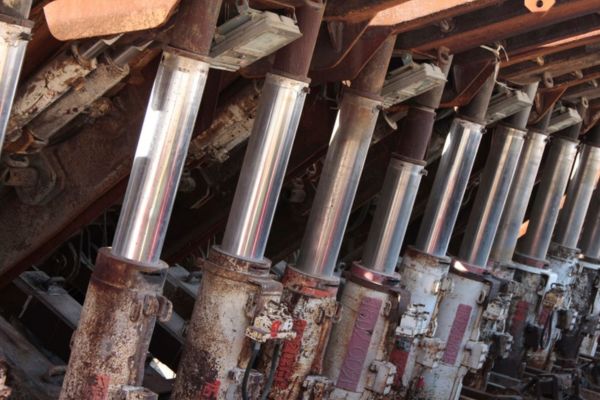
The working environment has a critical impact on the cylinder’s service life and reliability. High temperatures can accelerate seal aging, reduce hydraulic oil viscosity, and even affect the mechanical properties of metal components. Low temperatures may cause seals to harden and hydraulic oil to become too viscous. In dusty environments like mining sites or cement plants, if effective dust protection (e.g., wiper seals, rod covers) is not in place, abrasive particles can easily enter the cylinder, scratch the piston rod and cylinder bore, damage seals, and lead to serious internal or external leakage. Corrosive environments, such as chemical plants or offshore platforms, place strict demands on the corrosion resistance of cylinder materials, piston rods, and seals. Ignoring these factors and using generic cylinders often results in premature failure and frequent maintenance.
Taboo 2: Improper Material Selection – Compromised Strength and Durability
Material selection is the foundation of a hydraulic cylinder’s load-bearing capacity, service life, and environmental adaptability. If the investigation of working conditions is the “diagnosis,” then material selection is the “prescription.” Once the wrong materials are chosen, even the most sophisticated structural design cannot ensure stable and reliable performance under harsh conditions. Strength and durability will be severely compromised, potentially leading to safety incidents.
Risk of Instability Due to Insufficient Strength in Cylinder Tube and Piston Rod Materials
The cylinder tube and piston rod are the primary load-bearing components of a hydraulic cylinder. The tube must withstand high internal pressure, so the selected material must meet the required yield strength and tensile strength under design conditions, along with an appropriate safety factor. If the cylinder tube’s strength is insufficient, it may undergo permanent plastic deformation (bulging) under pressure, leading to increased internal leakage, reduced efficiency, or, in extreme cases, catastrophic rupture.
The piston rod mainly bears axial compression or tension. Its material must not only be strong but also offer adequate stability against buckling under compression. This is especially critical for long-stroke cylinders with relatively small rod diameters. If the rod material has a low elastic modulus or insufficient yield strength, it is highly susceptible to bending and instability under load, resulting in jamming, seal damage, or rod fracture.
Seal Material Incompatibility with Hydraulic Fluids and Operating Conditions
Seals may seem fragile compared to metal components, but they are vital to cylinder performance. Seal materials must be fully compatible with the hydraulic fluid (including oil type and additives), operating temperature range, motion speed, and external environment (such as exposure to chemicals or abrasives). Incompatibility can lead to swelling, hardening, cracking, or chemical degradation of the seals, causing rapid failure.
For instance, Nitrile rubber (NBR) seals may deteriorate quickly when exposed to certain synthetic hydraulic fluids or high-temperature environments. Fluorocarbon rubber (FKM/Viton®) offers excellent resistance to heat and oils but can become brittle in cold temperatures and may degrade when exposed to specific media such as amines. Choosing “universal” seal materials without assessing compatibility is a common reason for early hydraulic cylinder leakage.
Overlooking Special Material Requirements in Harsh Environments
Beyond basic strength and wear resistance, special working conditions demand more stringent material performance. In the chemical industry, hydraulic cylinders may come into contact with corrosive substances like strong acids, alkalis, or organic solvents. In such cases, standard carbon steel or low-alloy steel is inadequate. Materials such as stainless steel (e.g., 316L, duplex stainless), Hastelloy, or Monel alloys may be required for cylinder tubes, piston rods, and fittings to withstand corrosion.
Surface treatments for piston rods are also critical. While hard chrome plating is common, more corrosion- and wear-resistant options like nickel-based alloy coatings or ceramic coatings may be necessary in extreme environments. Ignoring these requirements often results in premature failure, frequent maintenance, and elevated replacement costs.
| Component | Primary Failure Mode | Safety Factor Type | Normal Conditions (n<sub>s</sub>) | Impact/Variable Load Conditions (n<sub>s</sub>) | Special/Critical Conditions (n<sub>s</sub>) | Design Basis (Typically Based on) | Remarks |
| Cylinder Barrel | Yielding, Burst | Strength | 2.0 ~ 3.0 | 3.0 ~ 5.0 | > 5.0 | Material Yield Strength (σ<sub>s</sub>) | Wall thickness should account for pressure pulsation and fatigue |
| Fatigue Crack Propagation | Fatigue | 1.5 ~ 2.5 (vs. fatigue limit) | 2.0 ~ 3.5 (vs. fatigue limit) | > 3.5 | Material Fatigue Limit (σ<sub>-1</sub>) | Detailed fatigue analysis required | |
| Piston Rod | Yielding, Fracture (Tension/Compression) | Strength | 2.0 ~ 3.5 | 3.0 ~ 5.0 | > 5.0 | Material Yield Strength (σ<sub>s</sub>) | Buckling analysis required for compression members |
| Buckling (Compression Rod) | Stability | 2.5 ~ 4.0 | 3.0 ~ 5.0 | > 5.0 | Critical Buckling Load (P<sub>cr</sub>) | Especially important for slender rods | |
| Fatigue Fracture | Fatigue | 1.8 ~ 3.0 (vs. fatigue limit) | 2.5 ~ 4.0 (vs. fatigue limit) | > 4.0 | Material Fatigue Limit (σ<sub>-1</sub>) | Pay attention to stress concentration at rod ends and cross-section changes | |
| End Cap / Cylinder Bottom | Yielding, Fracture | Strength | 2.0 ~ 3.5 | 3.0 ~ 5.0 | > 5.0 | Material Yield Strength (σ<sub>s</sub>) | FEA analysis recommended for complex geometries |
| Tie Rods / Bolts | Tension Failure, Shear Failure | Strength | 2.5 ~ 4.0 | 3.5 ~ 6.0 | > 6.0 | Material Yield Strength (σ<sub>s</sub>) | Consider preload and dynamic load impacts |
| Fatigue Fracture | Fatigue | 2.0 ~ 3.5 (vs. fatigue limit) | 3.0 ~ 5.0 (vs. fatigue limit) | > 5.0 | Material Fatigue Limit (σ<sub>-1</sub>) | Thread root is a typical fatigue weak point | |
| Clevis / Pin Shaft | Shear, Bearing, Bending | Strength | 2.5 ~ 4.0 | 3.0 ~ 5.0 | > 5.0 | Material Yield Strength (σ<sub>s</sub>) |
Note: This table is a general recommendation, the specific value of the safety factor should be combined with the relevant standards, the severity of the working conditions, the severity of the consequences of failure, material reliability, and the internal norms of the enterprise to determine the synthesis.
Taboo 3: Structural Design Flaws – Hidden Hazards from Stress Concentration
The structural design of a hydraulic cylinder is where material properties are translated into actual load-bearing performance. Any flaws in the design—especially at critical locations involving improper shapes, abrupt dimensional transitions, or poor connection methods—can lead to stress concentration. This is like a tiny ant hole in a strong dam: it may appear minor but can eventually cause fatigue cracks or insufficient static strength, posing a serious threat to equipment safety.
Structural Weaknesses in Critical Areas
Key structural weak points often lie in the load transmission zones, such as the rod end connections (e.g., threads, clevises, and eye mounts) and the junctions between the cylinder barrel and end caps (e.g., flange connections, threaded joints, tie-rod assemblies). These areas are subject to high stress and are inherently vulnerable.
For instance, the root of a threaded rod end, the edge of a clevis pin hole, or the area around flange bolt holes are all classic stress concentration zones. If the transition radii are too small or absent, the wall thickness is insufficient, or the fasteners (like bolts) are poorly selected or arranged, localized stress can significantly exceed the average design stress. Under dynamic or impact loads, these stress points can become the origin of fatigue cracks that eventually lead to fractures and system failure.
Risks from Poorly Matched Welding Design and Techniques
Welding is a common method used in cylinder fabrication—for example, welding ports to the barrel or welding certain end caps to the cylinder. However, welded joints are inherently discontinuous and prone to stress concentration and microstructural changes. If the welded structure is poorly designed—such as placing the weld seam in a high-stress zone, using undersized weld beads, or neglecting weld deformation and residual stress—the strength and fatigue life of the joint are greatly reduced.
The situation becomes even riskier if the selected materials have poor weldability or if the welding process parameters are not well controlled (e.g., inadequate preheating, improper post-weld heat treatment). Common weld defects such as cracks, lack of fusion, porosity, and slag inclusion can propagate quickly under service loads, leading to catastrophic failure.
Taboo 4: Insufficient Guidance and Support – Piston Rod “Eccentric Instability”
The guiding system of a hydraulic cylinder plays a critical role in ensuring the piston rod moves accurately and smoothly within the cylinder barrel while also bearing any side loads that may act on the rod. When guidance and support are inadequate, the piston rod can become misaligned during movement, leading to uneven wear, premature seal failure due to one-sided loading, and in severe cases, buckling under compressive force during the return stroke — a failure that can be catastrophic.
Improper Guide Bushing Length and Material Selection
The guide bushing — typically installed in the rod-end cap — is the main component responsible for guiding the piston rod. Its length (guide length) and material are key design parameters. If the guide length is too short, the piston rod will have poor alignment accuracy and reduced resistance to overturning moments, making it prone to wobbling under side loads. Generally, the ratio of guide length to piston rod diameter should meet specific design standards and be verified based on stroke length and applied forces.
Material selection for the guide bushing is equally important. The bushing must offer excellent wear resistance, a low coefficient of friction, and sufficient strength and rigidity. Common materials include bronze, cast iron, and filled PTFE (polytetrafluoroethylene). If the selected material lacks wear resistance or the fit between the bushing and rod is too loose, guiding accuracy will suffer, leading to premature wear and reduced service life.
Ignoring the Need for Intermediate Support in Long-Stroke Cylinders
In hydraulic cylinders with exceptionally long strokes — where the stroke-to-rod diameter ratio exceeds a critical threshold (often 10:1 or more, depending on operating conditions) — relying solely on the rod-end guide bushing is often insufficient to maintain stability throughout the entire stroke. When the piston rod is fully extended, its own weight and any slight initial curvature can lead to instability under compressive loads.
To mitigate this risk, the potential for buckling must be carefully evaluated during design. If necessary, intermediate support structures should be incorporated. These may be fixed supports (where space permits) or dynamic supports like floating rings that move with the rod. Overlooking this requirement and extending the stroke length without adding proper support is a common cause of instability and damage in long-stroke cylinders.
Neglecting Side Loads – The Hidden Culprit Behind Early Wear and Instability
In theory, a hydraulic cylinder’s piston rod should only experience axial loads. In practice, however, due to installation misalignment, deviations in load paths, or the structural characteristics of the equipment, piston rods often endure some degree of side loading. If these side loads are underestimated or ignored during the design phase — without verifying the load capacity of guide components (like guide bushings and wear rings) or applying measures to reduce lateral forces (e.g., using floating couplings or spherical bearings) — the result can be destructive.
Side loads generate abnormal contact stresses and wear between the piston rod, guide bushing, piston, and the cylinder’s internal surface. Over time, this not only causes leakage but also increases the clearance between components, further reducing rod stability. Ultimately, under the combined effect of axial and lateral forces, the rod may buckle and fail, posing serious reliability and safety issues.
Taboo 5: Poor Cushioning Design – When Impact Hits “Metal to Metal”
When a hydraulic cylinder drives a load at high speed and reaches the end of its stroke without effective deceleration measures, the piston collides directly with the end cap. This metal-to-metal impact creates intense shock and noise. Such uncontrolled collisions not only damage the cylinder itself (including the end cap, piston, and seals) but may also transmit destructive force to the entire machine structure. The result: reduced service life, potential system failures, and serious safety hazards.
Risks of Missing or Inadequate Cushioning
One of the most common — and dangerous — mistakes is omitting a cushioning mechanism altogether in cylinders used for high-speed motion or with high-load inertia. This is often found in low-cost systems or designs by less experienced engineers. The consequences are immediate and severe: extreme mechanical and hydraulic shock at the stroke end, loud noise, violent vibration, and long-term damage.
Common effects include:
- Loose mounting bolts;
- Fatigue in the piston rod-to-piston connection;
- Damaged seals due to repeated shock;
- Cracks in the end cap or cylinder body.
A less obvious but equally harmful issue is insufficient cushioning. Even if a cushion is included, it may not be capable of absorbing the kinetic energy of the moving parts. This often stems from undersized cushion chambers, improperly sized orifices, or miscalculated inertia and terminal speed. In these cases, the piston still slams into the end cap, just slightly softened — leading to progressive wear and premature failure.
Mismatched Cushioning Types: Fixed vs. Adjustable Cushions
Hydraulic cylinders typically use two types of cushioning: fixed and adjustable.
- Fixed cushions rely on a fixed orifice or tapered plunger (on the piston) entering a cushion chamber in the end cap. These designs are simple and cost-effective but offer only a fixed damping profile. That means they can’t adapt to changing operating conditions, such as variations in load or speed. When the application involves fluctuating dynamics, fixed cushions can either underperform (causing overshooting) or over-dampen (causing sluggish stops and longer cycle times).
- Adjustable cushions, on the other hand, incorporate a throttling valve to fine-tune the resistance during the cushioning phase. This allows the cylinder to better accommodate a range of conditions, delivering smoother and safer deceleration tailored to different speeds or load masses.
Failure to match the cushion type with the actual working environment is a frequent oversight. For instance, choosing a fixed cushion in a system with frequent load or speed changes may lead to unstable operation and poor energy absorption at stroke ends. To achieve optimal performance and safety, the cushion design must reflect both the expected dynamics and any variability in the application.
Taboo 6: Missing or Improper Air Bleed Design – Trapped Air Compromises System Performance
Air trapped inside a hydraulic system is a hidden menace. It can originate from dissolved gases in the hydraulic fluid, air drawn in through leaks, or residual air left in the lines after maintenance. If air accumulates inside a hydraulic cylinder — the key actuator in the system — and is not effectively expelled, it can lead to a host of operational problems. These include erratic motion, inconsistent speed, poor positioning accuracy, increased noise and vibration, accelerated oil oxidation, and in extreme cases, seal failure due to the “diesel effect.”
Hazards of Unpurged Air Inside the Cylinder
Air is significantly more compressible than hydraulic oil. When gas bubbles are present in the cylinder chamber, they compress under pressure. As the system pressure changes or reverses direction, these bubbles expand again. This compress-and-expand cycle creates fluctuations in the effective working volume of the cylinder, disrupting smooth piston motion. The result? Jerky movements, slow-speed crawling, and unstable stroke transitions.
In addition, when bubbles collapse within the fluid or pass through high-pressure orifices, they produce high-pitched noise and vibration. Over time, the presence of air reduces the stiffness of the hydraulic system, causing slower response and reduced control precision — unacceptable in applications requiring smooth operation or accurate positioning. For these precision-critical systems, internal air must be eliminated completely.
Common Mistakes in Air Bleed Valve Placement and Design
Even when designers understand the importance of venting air, mistakes in the positioning and selection of bleed valves are common. The most critical factor is placement. Air naturally collects at high points or stagnant corners of the hydraulic flow path. If air bleed valves are not located at these points, their effectiveness is severely compromised.
- For horizontally mounted cylinders, air bleed valves should be installed near the upper portions of both ends of the barrel.
- For vertically mounted cylinders, they should be placed on the top end cap or the highest point on the cylinder barrel.
Poor positioning leads to incomplete air evacuation, resulting in persistent system instability.
The type of bleed valve also matters:
- Screw plug-type valves are inexpensive but inconvenient to operate and prone to leakage.
- Manual bleed valves allow controlled air removal but require manual intervention, which isn’t ideal for systems needing frequent maintenance.
- Automatic air bleed valves offer convenience but come at a higher cost and may suffer from limited lifespan or reduced reliability in dirty or high-pressure environments.
Taboo 7: Inadequate Overpressure Protection – When the System “Runs Wild”
Hydraulic overpressure—also known as pressure surge or hydraulic shock—is a dangerous, high-intensity spike in system pressure caused by sudden changes in flow. These events often occur when valves close abruptly, cylinders reach the end of their stroke at high speeds, or external shocks affect the system. If not properly managed, these pressure peaks can far exceed normal working limits within milliseconds. The consequences range from damaged gauges and sensors to ruptured hoses, burst cylinders, and catastrophic failure that poses serious safety risks.
Causes and Consequences of Hydraulic Overpressure
Hydraulic surges typically stem from the following scenarios:
- Sudden Valve Closure or Direction Change When a directional or shut-off valve controlling a hydraulic cylinder closes too quickly, high-velocity oil flow is abruptly halted. The fluid’s kinetic energy transforms into a pressure spike. This phenomenon is especially severe in systems with long piping and high flow rates.
- Cylinders Hitting the Stroke End at High Speed If a hydraulic cylinder reaches the end of its stroke rapidly, and the cushioning design is inadequate or fails, the piston’s momentum transfers directly to the hydraulic fluid, creating an extreme, momentary pressure surge inside the chamber.
- External Impact Loads When the cylinder’s load experiences a sudden jolt—such as an excavator bucket hitting solid rock—the reactive force is transmitted back into the cylinder, causing a sharp pressure rise.
- System Resonance Under certain conditions, the hydraulic system’s natural frequency may align with pulsating sources like pumps or periodic load changes. This resonance amplifies pressure fluctuations, creating repeated surges.
The consequences of these surges are far-reaching: They can damage the cylinder structure, burst hoses, fatigue seals, destroy sensors, or even eject end caps violently. Beyond mechanical damage, surges lead to fluid leaks, shortened component lifespan, reduced system efficiency, and dangerous, chain-reaction failures.
Cylinder Pressure Design and Testing Shortcomings
As a pressure-bearing component, the hydraulic cylinder must be capable of withstanding not only its rated operating pressure but also occasional pressure peaks. This includes:
- Cylinder barrel, end caps, piston rod, and connection bolts—all must be evaluated for burst pressure conditions, not just normal operating pressure.
- Safety margins must be included in the material selection, wall thickness, and mechanical design.
However, in many designs, the focus remains on static pressure ratings. Engineers may underestimate surge peaks or use overly conservative designs that fail under real-world loads. Inadequate pressure ratings, weak materials, or thin wall sections are common failure triggers.
Additionally, pressure and burst testing during manufacturing is critical. If testing pressure is too low or the method is not standardized, defects in design or assembly may remain hidden until the product is in service—when failure becomes dangerous and costly.
Conclusion
We encourage you to carefully review each design taboo and recommendation discussed in this article. Reflect on your own project experience: Which of these issues have you encountered before? Which risks should you be especially vigilant about in future applications?
If you found this guide helpful for yourself or your engineering team, we invite you to share it. Should you have any custom hydraulic cylinder requirements, feel free to contact us anytime. Our expert team is ready to provide you with tailored technical support and reliable solutions.
FAQ
What causes overpressure in a hydraulic cylinder?
Sudden valve closure, cylinder end impact, external shocks, or system resonance can all cause pressure surges.
Why is cushioning necessary at the end of a cylinder stroke?
It slows down the piston to prevent metal-to-metal impact, reducing damage and extending system life.
How can trapped air affect hydraulic cylinder performance?
Air causes erratic motion, increased noise, reduced accuracy, and slower response due to its compressibility.
What’s the risk of poor material selection in hydraulic cylinders?
It can lead to rod buckling, barrel deformation, seal failure, or even catastrophic rupture under high loads.
Why is guide support important for long-stroke cylinders?
Insufficient support can cause rod deflection, uneven wear, seal damage, and buckling under compression.
How can I protect my cylinder from pressure spikes?
Use properly sized and positioned relief valves, accumulators, and throttle valves, and ensure the cylinder is pressure-tested.