Precise terminology enables professionals in the field to communicate effectively and ensure that the right components are selected for specific tasks. A strong grasp of hydraulic fitting definitions not only prevents errors during system design but also helps streamline troubleshooting and repairs, making system maintenance more efficient.
Basic Definitions of Hydraulic Fittings
Hydraulic Fitting
A hydraulic fitting is a mechanical component designed to connect two or more elements of a hydraulic system, such as tubes, pipes, hoses, or other fittings. These connections facilitate the flow of hydraulic fluid while maintaining system integrity under high pressure and various environmental conditions. Hydraulic fittings are essential for ensuring the secure and efficient transfer of fluid between different components of the hydraulic circuit.
There are several types of hydraulic fittings, each designed for specific applications:
- Adapters: Used to connect two dissimilar thread types or sizes. These are often used when different parts of the system have different thread types or dimensions.
- Elbows: These fittings allow fluid to change direction, typically at 90° or 45°, and are used where space constraints require a directional change in the hydraulic lines.
- Tees: T-shaped fittings used to split or merge hydraulic fluid flow between three connected pipes or hoses.
- Couplings: Designed for quick connects or disconnects between hoses, pipes, or machinery, often used for ease of maintenance or system reconfiguration.
Each of these fitting types has specific characteristics suited to particular system requirements, whether it’s for flexibility, pressure control, or durability.
Thread Terminology
Thread terminology is essential when selecting and identifying hydraulic fittings, as the thread type and specifications directly affect the fitting’s compatibility with other components. Understanding the different thread-related terms helps ensure that fittings are correctly matched to their corresponding ports or adapters.
Thread Form
The thread form refers to the shape of the threads on the fitting, which is critical for ensuring the correct connection between the fitting and its corresponding port or hose. The form is determined by the angle between the sides of the thread (the flanks). For example, common thread forms include:
- BSP (British Standard Pipe): Has a 55° thread angle.
- NPT (National Pipe Thread): Uses a 60° thread angle.
- JIC (Joint Industrial Council): Also uses a 37° angle for flare-type fittings.
The correct thread form is crucial because mismatched thread forms can result in poor sealing, leakage, and eventual system failure. Identifying the right thread form requires careful inspection of the fitting’s geometry and ensuring it matches the port or coupling to which it will connect.
Thread Pitch
Thread pitch refers to the distance between two adjacent threads on a fitting, usually measured in millimeters (for metric threads) or threads per inch (for imperial threads). It is essential to match the thread pitch between fittings to ensure a proper seal and fit. For example, a 1.5mm pitch means that there is a 1.5mm gap between two consecutive threads, which affects the fitting’s tightness and sealing capabilities.
Measuring thread pitch can be done using tools like a pitch gauge or calipers, but the pitch must match between fittings and ports. If the pitch does not match, it can lead to cross-threading, improper sealing, or damage to the threads.
Threads per Inch (TPI)
In imperial systems, Threads per Inch (TPI) is a critical measurement that identifies the number of threads in one inch of length. For example, a 1/4″-20 fitting would have 20 threads in every inch. TPI is especially important for threaded fittings such as NPT, BSP, and JIC, where the number of threads determines how tightly the fitting will seal.
The TPI measurement is used in the context of imperial-sized fittings and helps in identifying the type of thread. It’s essential to ensure that the TPI of both the fitting and the port are the same for a secure, leak-free connection. A thread gauge is often used to measure TPI and ensure proper matching.

Nominal Size vs Dash Size
Understanding the difference between Nominal Size and Dash Size is crucial for correctly identifying and selecting hydraulic fittings. These terms refer to the way the size of fittings is classified, which can sometimes be confusing.
Nominal Size
Nominal size is a general reference to the size of the fitting or pipe used for identification purposes, but it does not correspond to an exact measurement. For instance, a 1/2-inch nominal pipe may have an actual outside diameter (O.D.) of 0.840 inches. Nominal size is a standardized reference that helps categorize fittings and components, but it does not directly relate to the precise dimensions needed for proper fitting selection.
Nominal size is commonly used when discussing pipes, tubes, and fittings, and it is often confused with actual dimensions. However, it serves as a simplified reference to group fittings into common categories based on their general size.
Dash Size
On the other hand, dash size refers to the specific size measurement of a hydraulic fitting, typically in inches or millimeters. Dash sizes are used to indicate the fitting’s diameter and are part of the fitting’s part number. For example, a fitting with a part number of “08” typically refers to a 1/2-inch fitting, as the dash size corresponds to a specific measurement.
Dash sizes are essential in making sure the fitting is compatible with other components, especially when precise sizing is necessary for proper fluid flow and sealing. The dash size is often listed alongside the part number to make identification straightforward and ensure the correct fitting is chosen for a system.
Understanding Thread Types and Thread Characteristics
Common Thread Types
Thread types are crucial when selecting hydraulic fittings, as the thread form determines the compatibility and sealing ability of the connection. Various thread standards have been developed globally, each with its own design specifications, intended uses, and applications. Understanding the differences between these common thread types will help ensure the proper fitting is chosen for specific hydraulic systems.
BSP (British Standard Pipe)
BSP threads are a type of parallel (BSPP) or tapered (BSPT) thread commonly used in the United Kingdom and other regions following British standards. BSPP is often used for hydraulic systems that require non-leaking connections, where the sealing is achieved through the compression of an O-ring or seal. BSPT, on the other hand, has a tapered thread that seals by wedging the threads together, making it suitable for applications where higher pressure or more robust seals are needed.
Applications: Common in the UK, Europe, and other regions, BSP threads are found in industries like automotive, plumbing, and hydraulic systems, particularly where O-rings or compression fittings are used.
NPT (National Pipe Thread)
NPT is a widely used thread type in North America and is designed for creating tight, leak-proof connections in systems involving fluid or gas. It is a tapered thread (like BSPT) that seals by wedging the threads together. NPT threads are commonly used in applications that require high-pressure fluid transfer.
Applications: NPT threads are often found in North American hydraulic systems, as well as in plumbing, automotive, and industrial applications, where the fluid pressure is high and leakage prevention is essential.
JIC (Joint Industrial Council)
JIC threads are a type of flare fitting thread, primarily used in North American hydraulic systems. JIC threads have a 37-degree flare angle, and the sealing occurs between the flat face of the fitting and the flare of the hose or pipe. These threads are typically used for high-pressure applications because the flare creates a tight seal that resists vibration and high stresses.
Applications: JIC is commonly used in high-pressure applications such as hydraulic systems in construction equipment, aircraft, and other industrial machinery, where vibration resistance is critical.
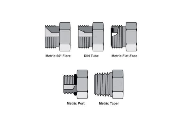
Metric Threads
Metric threads are commonly used worldwide and are particularly prevalent in Europe and Asia. These threads follow the ISO metric system, with sizes indicated by the diameter and pitch in millimeters. Unlike imperial thread types (e.g., NPT, JIC), metric threads use a direct measurement system, making them easier to understand and apply across international markets.
Applications: Metric threads are standard in many European and Asian countries for hydraulic systems, automotive applications, and fluid transfer systems in industries ranging from manufacturing to robotics.
ORB (O-Ring Boss) and ORFS (O-Ring Face Seal)
ORB and ORFS are thread types used in hydraulic fittings designed to create a leak-proof seal using an O-ring. ORB is a straight thread with a machined groove for an O-ring, while ORFS uses a flat face and an O-ring to seal the connection. Both threads offer reliable sealing and are resistant to the leakage of high-pressure fluids, making them ideal for applications that require superior sealing performance.
Applications: ORB and ORFS are typically used in high-pressure hydraulic systems in industries such as aerospace, oil and gas, construction, and heavy equipment.
Comparison of Different Thread Types and Their Applications
Each thread type serves a specific purpose based on factors such as pressure, leak prevention, sealing method, and the mechanical stresses the system is subjected to. Here is a brief comparison of the thread types discussed:
| Thread Type | Thread Form | Sealing Method | Applications |
| BSP | Parallel or Tapered | O-ring(BSPP)or thread compression(BSPT) | Automotive, plumbing, low-pressure hydraulic systems |
| NPT | Tapered | Thread compression | High-pressure systems, plumbing, industrial equipment |
| JIC | Flare (37° angle) | Flare face seal | High-pressure applications, construction machinery, industrial systems |
| Metric | Parallel | O-ring or thread compression | Global use in hydraulic, automotive, and fluid systems |
| ORB/ORFS | Straight or Flat | O-ring seal | High-pressure, aerospace, oil &gas industries |
Thread Form
The thread form refers to the geometric shape of the thread and its angle. This angle, known as the flank angle, is a key factor in determining whether two components will properly mate and seal. It directly affects the torque required to tighten the fitting and the overall performance of the connection.
- Flank Angle: The flank angle is the angle between the flanks (sides) of a thread. For example, NPT threads have a 60-degree flank angle, while BSP threads have a 55-degree flank angle. The flank angle must be compatible between the fitting and the port to ensure proper engagement and sealing.
- Compatibility: If two threads with different flank angles are mated, the connection will likely not form a proper seal. It is essential to identify the correct thread form to avoid potential leaks and system failure.
Major vs Minor Diameter
When identifying threads, the major diameter and minor diameter are two critical measurements, especially when comparing male and female threads.
- Major Diameter: The major diameter is the largest external diameter of a male thread or the smallest internal diameter of a female thread. For male threads, it is measured from crest to crest, while for female threads, it is measured from root to root. This measurement is crucial for determining the compatibility of a male fitting with a female port.
- Minor Diameter: The minor diameter is the smallest internal diameter of a male thread or the largest internal diameter of a female thread. This measurement is important for ensuring that the fitting can securely engage with the port without excessive play or misalignment.
By using a caliper or micrometer, these diameters can be measured, and their values can be compared to known specifications to verify thread compatibility.
Thread Pitch and Pitch Measurement
Thread pitch refers to the distance between two adjacent thread crests, and it is essential for proper thread identification. It plays a significant role in determining how tightly the threads will fit together.
Pitch is usually measured in millimeters for metric threads or threads per inch (TPI) for imperial threads.
Pitch Measurement: To measure thread pitch, a pitch gauge is used. This tool allows you to match the gauge’s teeth with the threads to determine the correct pitch. For imperial threads, you would typically count the number of threads per inch (TPI), while for metric threads, you measure the distance between crests in millimeters.
Understanding Fitting Sizes and Classification
How Fittings Are Classified
Hydraulic fittings are classified based on several factors, such as thread type, material, size, and specific application. Fitting part numbers play a key role in this classification, providing essential information about the fitting’s dimensions, thread configuration, and type of connection. Understanding how to interpret these part numbers is critical for selecting the right fitting for any hydraulic system.
Part Numbering and Its Significance
A hydraulic fitting part number typically includes several elements that denote specific characteristics of the fitting. These include:
- Part Series/Group: The first section of the part number often refers to the series or group of fittings the component belongs to. This grouping helps categorize fittings based on their application or the material used.
- Dash Size: The dash size (e.g., -04, -06, -08) indicates the size of the fitting, specifically the outer diameter of the tube or hose that the fitting is designed to connect to. This number does not necessarily correlate with the exact measurement of the fitting but provides a quick reference to the approximate size.
- Thread Information: The thread type, pitch, and diameter are often specified in the part number. The exact configuration may vary based on whether the fitting has NPT, JIC, BSP, or another type of thread.
By understanding part numbers, hydraulic professionals can quickly identify the most important attributes of a fitting, such as size, thread type, and compatibility with hoses, tubes, or ports.
How to Read Hydraulic Fitting Part Numbers
To illustrate, let’s break down a typical hydraulic fitting part number:
Example: 0708-04-04
- 0708: Part series or group
- 04: Dash size, indicating the fitting is designed for a 1/4″ tube or hose
- 04: Thread size or type, showing the thread configuration (e.g., NPT, BSP, etc.)
In this example, the part number quickly provides critical information, helping users determine the correct fitting for their application.
Fitting Sizing and Dash Numbers
Fitting sizes are often represented using dash numbers, which denote the diameter of the hose or tube that the fitting is designed to connect to. However, the dash number itself does not represent the exact dimension of the fitting; it is a convenient identifier that correlates to a particular size range.
How Sizing Is Determined by Dash Numbers
Dash numbers are typically used in hydraulic systems to indicate the internal or external diameter of a hose or tube that the fitting connects to. For example:
- Dash -04 generally refers to a fitting that connects to a 1/4″ tube or hose.
- Dash -06 indicates a fitting for a 3/8″ tube or hose.
- Dash -08 is used for a fitting for a 1/2″ tube or hose.
These dash numbers are standardized across many hydraulic systems, which allows for easier fitting identification and selection. However, it is essential to keep in mind that the actual measurements may slightly vary, especially between different manufacturers or systems.
The Relationship to Actual Dimensions
The dash number provides an approximation of the size but does not always match the exact diameter. For example:
Dash -04: Often refers to a 0.375″ nominal size, which corresponds to a 1/4″ tube or hose. However, the actual outer diameter (OD) might be slightly different depending on the specific fitting type.
To ensure proper selection, it is crucial to cross-reference dash sizes with actual measurements of the components involved, especially when working with systems requiring precise connections.
Conversion Between Nominal Size and Actual Size Measurements
In some cases, the nominal size of a fitting or hose does not directly match its physical dimensions. This difference can be seen in both nominal size and actual size measurements. Nominal size refers to a rounded figure used for easy reference, while actual size refers to the true dimension of the fitting.
For instance:
- Nominal Size (1/4″): Refers to the reference size used for identifying the fitting and may not match the exact dimension.
- Actual Size (0.375″): Refers to the exact external or internal dimension of the fitting or hose.
Engineers, technicians, and hydraulic professionals need to be familiar with both nominal and actual sizes to ensure proper fitting selection and avoid potential issues with misfitting components.
Metric vs. Imperial Sizing
Fitting sizes can be classified in either metric or imperial systems, and understanding the differences is crucial when selecting components for international applications or when working with systems from different regions.
Key Differences in Measurement Systems
- Imperial System (Inch-based): Commonly used in North America, the imperial system measures fitting sizes in fractions of an inch (e.g., 1/8″, 1/4″, 1/2″, etc.). The dash numbers are directly related to these measurements. For example, a dash -04 fitting corresponds to a 1/4″ hose or tube.
- Metric System (Millimeter-based): In regions like Europe and Asia, the metric system is used, where fitting sizes are measured in millimeters (e.g., 6mm, 8mm, 12mm). The metric system offers more precision, as it avoids the need for fractional measurements.
The Impact of These Differences on Fitting Selection and Compatibility
Hydraulic fittings made for imperial-sized systems cannot be directly used with metric-sized systems, and vice versa. The primary issue lies in the sizing and thread dimensions, which may not align correctly.
For example, a dash -06 (3/8″) imperial fitting is not directly interchangeable with a 6mm metric fitting, as their dimensions are not the same. This mismatch can lead to issues with sealing, leakage, and overall system performance.
Understanding Pressure Ratings and Flow Capacity
Pressure Rating
The pressure rating of a hydraulic fitting refers to the maximum pressure that the fitting is designed to withstand under normal operating conditions. It is a critical parameter when selecting fittings for hydraulic systems, as using a fitting with an insufficient pressure rating can lead to catastrophic failures, including leaks, rupture, or damage to other components.
What Pressure Rating Means for Hydraulic Fittings
Pressure ratings are usually expressed in terms of pounds per square inch (PSI), bar, or MPa (megapascals). These ratings indicate the maximum internal pressure that the fitting can safely handle. There are a few key factors to consider:
- Operating Pressure: The maximum pressure at which the system is designed to work. This is typically lower than the fitting’s maximum pressure rating, providing a safety margin.
- Burst Pressure: The pressure level at which the fitting will fail. The burst pressure is much higher than the operating pressure and serves as a critical safety threshold.
- Working Pressure: Often referred to as the nominal pressure, it is the typical pressure the system will experience during normal operations, usually lower than both burst and maximum pressure ratings.
How to Read Pressure Ratings
Hydraulic fitting manufacturers often provide pressure ratings as part of the technical specifications. It is crucial to ensure that the fitting’s pressure rating matches or exceeds the maximum operating pressure of the system. When reviewing the ratings:
- Operating Pressure should align with the typical pressure the system will operate under.
- Burst Pressure provides a safety factor, indicating the point at which the fitting will fail under extreme conditions.
- The Pressure Class of the fitting, such as Class 150, Class 300, or Class 600, may also be mentioned, with higher classes indicating the ability to handle greater pressure.
When selecting hydraulic fittings, always match the fitting’s pressure rating with the system’s maximum operating pressure. It’s essential to factor in safety margins and avoid using fittings that are rated below the maximum operating pressure of the system.
Flow Capacity
The flow capacity of a hydraulic fitting refers to the volume of fluid that can pass through the fitting within a given period without causing pressure loss or flow restrictions. A fitting’s flow capacity directly influences the overall efficiency of the hydraulic system and its ability to operate smoothly under various conditions.
How Fittings Influence Flow Capacity and System Efficiency
Flow capacity is determined by several factors, including the size and design of the fitting. When fluid flows through a fitting, the following elements affect its ability to maintain efficient flow:
- Fitting Size: The diameter of the fitting directly impacts the flow capacity. Larger diameter fittings generally allow more fluid to pass through at a given pressure, reducing flow restrictions.
- Design of the Fitting: Fittings with more streamlined internal geometries (i.e., smooth interior surfaces, and reduced sharp bends) will cause less turbulence, resulting in lower pressure losses and higher flow capacity. Conversely, poorly designed fittings with rough interiors or restrictive geometries can create excessive resistance to flow.
- Connection Type: The type of connection (e.g., threaded, flanged, quick-connect) can also impact flow capacity. For example, quick-connect fittings may have internal restrictions to facilitate easy disconnection, which can affect flow when compared to a more permanent, sealed fitting.
Relationship Between Fitting Size, Design, and Fluid Flow
The relationship between fitting size, design, and fluid flow is directly correlated. A well-designed fitting with a larger bore size will facilitate better flow, while a fitting with a poor design or a small bore will cause flow restrictions, resulting in increased system pressure, reduced efficiency, and potential overheating.
- Flow Rate: The flow rate, measured in gallons per minute (GPM) or liters per minute (LPM), depends on the fitting’s size and ability to maintain smooth, unrestricted fluid flow.
- Pressure Drop: As fluid flows through fittings, pressure naturally drops due to friction and flow restrictions. By selecting appropriately sized and designed fittings, the pressure drop can be minimized, allowing the system to run more efficiently.
Conclusion
As hydraulic systems evolve, so too does the terminology and the precision required to manage them effectively. We encourage all professionals to regularly review fitting specifications, ensure correct installation, and use proper diagnostic tools. If you need any hydraulic fittings, please contact us!
FAQ
What is a hydraulic fitting?
A hydraulic fitting is a connector used in fluid systems to join pipes, hoses, or tubes, ensuring leak-free and efficient fluid transfer. They come in various types, such as elbows, tees, and adapters.
What is the difference between BSP and NPT threads?
BSP (British Standard Pipe) uses parallel threads for sealing, while NPT (National Pipe Thread) uses tapered threads that create a tighter seal when tightened. BSP is more common in Europe, while NPT is often used in North America.
How do I determine the correct size for a hydraulic fitting?
Fitting sizes are typically determined by the dash size (e.g., 04, 06) or the nominal size. The dash size corresponds to the internal or external diameter of the fitting, while the nominal size is a reference size and may differ slightly in actual measurements.
What is the importance of thread pitch in hydraulic fittings?
Thread pitch refers to the distance between thread crests and is essential for ensuring compatibility between fittings. Incorrect thread pitch can lead to leaks or mechanical failure.
Why is pressure rating important for hydraulic fittings?
The pressure rating indicates the maximum pressure the fitting can safely handle. Choosing a fitting with the appropriate pressure rating prevents failure under high-pressure conditions, ensuring system safety.
Can I use metric and imperial fittings together?
It is not recommended to mix metric and imperial fittings due to differences in thread types and sizes. Compatibility issues can lead to poor seals, leaks, and system failure. Always ensure fittings match the system specifications.