A useful report identifies the exact sample, lists each controlled characteristic against an approved reference, records the method and result, and preserves batch traceability. A part number, product photo, or small group of caliper readings cannot support replacement approval because the connection, seal, hose side, ferrule, and installation geometry may differ independently. A TP43 fitting dimension report should therefore present nominal requirements, tolerances when available, measured values, inspection methods, instrument identities, and pass/fail decisions in a form another reviewer can reproduce. It supports dimensional evaluation, but it does not by itself prove hose compatibility, crimp suitability, pressure capability, or safe interchangeability.
A Few Dimensions Cannot Define a Complete Fitting
Replacement approval fails when a report measures only the easiest visible features. Overall length and thread outside diameter may look close while the thread form, pitch, seat, ferrule, stem profile, or elbow centerline remains wrong.
Dimensions work as a controlled set
Each feature must be evaluated in relation to the fitting configuration. A straight male fitting, a female swivel elbow, and a flange-style connection do not need the same characteristic list. The approved drawing, verified reference sample, or other accepted technical specification should determine which dimensions control fit and function.
The report should also distinguish identification from acceptance. “TP43-style” or a Parker 43 cross-reference can narrow the product family under review, but it does not establish that a replacement is an original Parker product or that every dimension and assembly requirement matches.
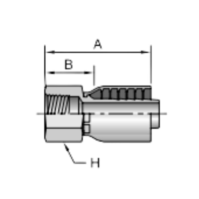
Photos support, but do not replace, data
Clear photos help reviewers confirm orientation, locate measurement points, see marking, and understand an unusual feature. They cannot reveal a hidden stem profile, prove thread pitch diameter, establish a seat angle accurately, or show whether a reported value was measured from the correct datum.
Use annotated images as navigation aids within the report. Every acceptance decision should still point to a defined characteristic, requirement, method, result, and disposition.
Start With an Unambiguous Report Header
The header determines what the measurements actually represent. Without product and sample identity, even accurate values may be assigned to the wrong size, orientation, revision, or lot.
Product and technical-reference fields
Record the complete product description, internal or supplier part number, cross-reference term when applicable, connection-side size, hose-side size, and straight, 45-degree, or 90-degree configuration. Include the approved drawing or specification number and revision that supplies the nominal requirements. If the technical reference is not yet approved, label its status rather than presenting draft information as final acceptance criteria.
The header should also identify the inspection date, report number, inspection location, and responsible reviewer. A TP43 reference must remain an identification term; it should not be used to imply brand origin or verified interchangeability.
Sample and batch identity
Each sample needs an identifier that connects it to the delivered lot or batch. When several pieces are measured, present results by sample rather than averaging away individual failures. The report should show the order or receiving reference, lot identity, sampled quantity, and any packaging or marking information used to preserve the chain.
Useful header data includes:
- Report number, date, and approved technical reference
- Complete fitting identity, size combination, and orientation
- Sample identifiers and lot or batch number
- Purchase order, receiving, or trial-order reference
- Inspector and review or approval status
Verify the Connection End With Suitable Methods
Connection approval requires more than a nominal name and approximate diameter. Thread form, diameter, pitch or TPI, straight or tapered construction, sex, engagement, and connection geometry must agree with the approved reference.
Thread characteristics and gauges
List each required thread characteristic separately. A caliper may screen an accessible major or minor diameter, but it does not establish pitch diameter, thread form, or functional engagement. Pitch gauges, specified plug or ring gauges, optical methods, or other approved instruments answer different questions and must be selected for the stated thread standard.
The report should identify the gauge type, instrument or gauge number, status, and result. Do not invent universal gauge classes or tolerances; use the requirements defined by the applicable drawing, standard, or inspection plan.

Connection geometry beyond the thread
Swivel nuts, hex dimensions, flange faces, pilots, counterbores, undercuts, and other connection details may affect assembly or clearance. Report only those relevant to the specific fitting, but do not omit a feature simply because it is harder to measure. If a dedicated fixture or profile method is required, identify that need rather than substituting an approximate caliper value.
A functional trial with an unknown port should not replace controlled thread verification. Forcing mismatched components can damage threads and create false confidence from partial engagement.
Document the Sealing Face and Seat
Two connections can have similar threads yet seal by different mechanisms. The report must identify the sealing feature independently from the thread so a matching diameter does not conceal an incompatible seat, face, cone, or O-ring arrangement.
Sealing geometry and condition
Depending on the configuration, relevant characteristics may include seat or cone geometry, flat-face position, sealing diameter, groove location, pilot relationship, and the presence of an O-ring or bonded sealing element. The approved reference determines the actual list and measurement method. Do not infer or invent a seat angle because the fitting resembles a familiar standard.
Visual condition should be reported separately from dimensional conformity. Scratches, dents, burrs, coating buildup, damaged grooves, or contamination may compromise sealing even when a major dimension passes.
Make the measurement location clear
Seat and face results are difficult to interpret when the datum or contact points are omitted. An annotated drawing view or photo can show where the characteristic begins and ends. For angular or profile requirements, identify the instrument and method that can resolve the feature reliably.
Thread sealant is not a corrective action for the wrong sealing face, seat, or connection standard. A discrepancy requires containment and technical review, not an assembly workaround.
Capture the Hose Side, Stem, and Ferrule
Dimensional similarity at the port does not prove that the replacement belongs with the intended hose. The hose-side report must address the stem and ferrule characteristics controlled by the fitting series and approved assembly data.
Stem and nipple characteristics
Record the hose-side nominal size and the dimensions or profiles that the approved technical reference identifies as critical. These may involve insertion-related geometry, stem sections, retention features, transitions, or other configuration-specific details. The exact list must come from verified data rather than an assumed profile shared by all one-piece fittings.
Do not present one insertion depth, skive rule, or crimp diameter as universally valid. The current hose manufacturer, hose series, construction, fitting series, ferrule design, crimp equipment, die, and crimp specification must be confirmed for assembly.

Ferrule identity and condition
The report should state whether the ferrule is preassembled or retained as expected and identify the characteristics being checked. Note visible damage, deformation, incorrect retention, or a mismatch with the approved sample or drawing. A ferrule that appears to fit over the stem is not proof that it will compress the intended hose correctly.
Where ferrule dimensions are required, show their nominal requirement, tolerance if available, result, and method like any other controlled characteristic. Do not reduce the report to “ferrule present.”
Include Overall Geometry and Installation Dimensions
The fitting can pass thread and hose-side checks but still fail in the machine because its body geometry interferes with adjacent components. Overall length, elbow centerline, drop, orientation, and wrench-access features should be included when they affect installation.
Straight and elbow measurements
For straight fittings, the controlling dimensions may use sealing, shoulder, body, or hose-side datums. Elbows require clearer definitions because measuring along an outside curve is not equivalent to locating the connection and hose centerlines. Report the angle and centerline-related dimensions specified by the drawing rather than a vague “same overall size” statement.
Use a fixture, height gauge, optical system, or other suitable method when caliper access does not provide a repeatable result. The method should reflect the required tolerance and geometry, not merely the tools available on the inspection bench.
Clearance and assembly envelope
Swivel-nut diameter, hex size, ferrule envelope, bend orientation, and rotation range can determine whether tools and neighboring parts have enough room. These may be dimensional or functional observations depending on the approved plan. Record them explicitly when the replacement application has restricted space.
Installation photos and equipment measurements can help define the required envelope, but they do not replace fitting-level controls. Keep the application requirement linked to the characteristic that addresses it.
Present Requirements, Methods, and Results Together
A report becomes actionable when each row explains what was required and how the decision was reached. Lists of unlabeled numbers force the reviewer to guess which value is nominal, measured, or acceptable.
Practical report fields
| Field | Purpose | Review question |
| Characteristic and drawing location | Defines what is controlled | Is the feature unambiguous? |
| Nominal requirement | States the target | Does it match the approved reference? |
| Tolerance or acceptance rule | Defines allowable variation | Is the criterion authorized and current? |
| Measured or observed result | Records sample evidence | Is each sample result visible? |
| Method and instrument ID | Explains how evidence was obtained | Is the method capable and traceable? |
| Pass/fail and remarks | States disposition | Are exceptions clearly controlled? |
Nominal dimensions describe intended targets; tolerances define permitted variation; measured results state what the identified sample produced. A pass/fail decision compares the result with the approved rule. None of these fields should be substituted for another.
Preserve raw results and measurement status
Do not report only an average when individual values determine acceptance. Identify out-of-range, not-measured, not-applicable, or pending characteristics clearly. Rounding should not hide a borderline result, and units should remain consistent with the technical reference.
The instrument record should show enough information to confirm that the equipment was suitable and within its required status at the time of inspection. If measurement uncertainty or method capability affects the decision, escalate it under the approved quality process rather than declaring a convenient pass.
Control Traceability, Exceptions, and Approval
The completed report should connect results to the sample and preserve every exception. Dimensional evidence without disposition leaves the replacement decision unresolved.
Batch chain and exception records
Link sample IDs to the lot, carton, order line, and receiving record. If parts are separated after inspection, maintain the accepted or held identity in storage. Mixed batches should not inherit a result from a sample that cannot be traced to them.
For every deviation, record:
- The affected characteristic, sample, and lot
- The approved requirement and actual result
- Containment applied to remaining material
- Technical review, corrective action, or concession status
- Final disposition and approving authority
Approval boundaries
Dimensional approval means only that the stated characteristics met the stated dimensional criteria for the identified samples or lot under the plan. It does not establish material grade, surface-treatment performance, pressure rating, fluid or temperature suitability, or hose-and-crimp compatibility unless separate verified evidence covers those areas.
The final replacement decision should combine the dimension report with material records, thread and sealing verification, hose assembly data, application requirements, and controlled validation where applicable. Safety-critical assemblies should never be approved from an unverified cross-reference, a single attractive sample, or dimensional similarity alone.
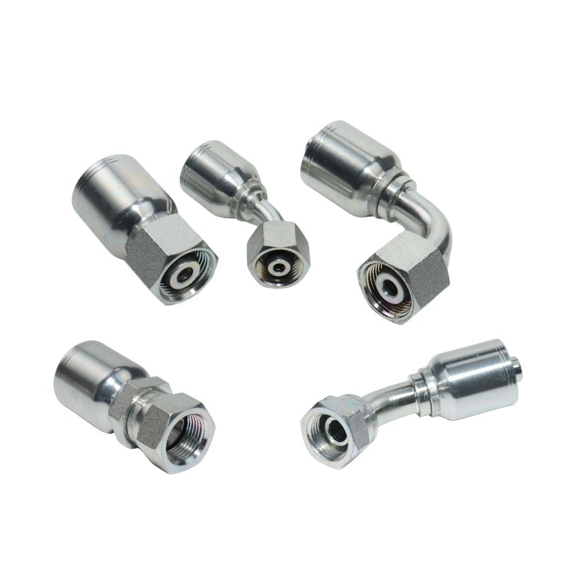
Dimension-report checklist
Before review, confirm the product description, size combination, orientation, reference drawing and revision, sample IDs, lot number, and order link. For the relevant configuration, include thread form and verification, sealing geometry and condition, hose-side stem and ferrule characteristics, key body dimensions, overall or centerline geometry, and installation-clearance features.
Each characteristic needs a nominal requirement, tolerance or acceptance rule when available, individual result, unit, method, instrument identity, and pass/fail status. Attach annotated photos only as support. Record missing data and deviations openly, then combine the dimensional report with material, hose, crimp, pressure, temperature, fluid, and application evidence before approving a replacement.
Conclusion
A defensible dimension report is a traceable comparison, not a collection of caliper readings. Identify the exact fitting, technical reference, samples, and batch; then report connection, sealing, hose-side, ferrule, body, and installation characteristics relevant to that configuration. Keep nominal requirements, tolerances, measured values, methods, and pass/fail decisions in separate fields so another reviewer can follow the logic. Photos clarify locations but cannot replace gauges or measured data, and dimensional acceptance cannot prove material, crimp, pressure, or application suitability. Before approving a TP43-style replacement, assemble the report with verified hose and fitting data, material records, application conditions, and documented exception decisions. Those combined records give a TP43 fitting dimension report its practical approval value.
Frequently Asked Questions
Can one approved sample define every future batch?
No, one sample demonstrates only the characteristics checked on that identified sample. Repeat orders still need agreed batch traceability and inspection controls to support continued conformity.
Should the report include every possible fitting dimension?
No, it should include every characteristic required by the approved reference and risk plan for that configuration. Adding uncontrolled measurements can confuse review without improving the decision.
Is a caliper enough for thread verification?
No, a caliper can support preliminary diameter checks but cannot fully verify thread form, pitch diameter, taper, or functional fit. Use the specified gauges and methods for the required thread standard.
Can dimensional results prove crimp compatibility?
No, dimensions alone cannot prove a safe hose-and-crimp combination. Current data for the exact hose, fitting, ferrule, machine, die, and crimp specification remains necessary.
How should a missing tolerance be reported?
It should be marked as unresolved rather than assigned an invented limit. Obtain an approved drawing, specification, or technical decision before issuing a final pass/fail result for that characteristic.