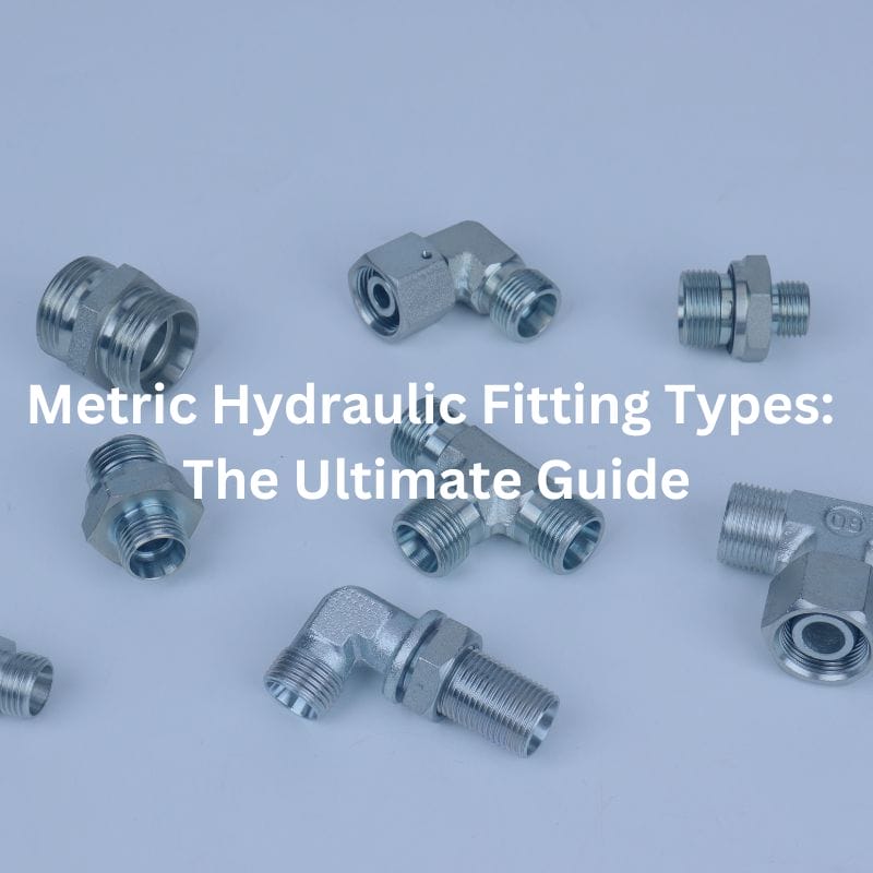
Metric Hydraulic Fitting Types: The Ultimate Guide
Table of Contents
Introduction
Did you know that hydraulic systems power more than 70% of industrial machinery worldwide? In the world of hydraulic systems, understanding the types of metric hydraulic fittings is crucial for ensuring optimal performance and reliability. This guide aims to provide comprehensive and actionable information on metric hydraulic fittings, their types, and their applications.
What is the classification of metric hydraulic fittings?
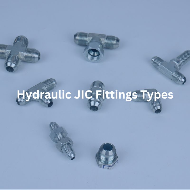
Metric hydraulic fittings are connectors used in hydraulic systems to join components, ensuring a secure and leak-free connection. They come in various types such as threaded, flanged, and quick-connect fittings, and are essential for maintaining the efficiency and safety of hydraulic machinery by providing reliable and precise connections tailored to metric measurements.
Understanding Metric Hydraulic Fittings
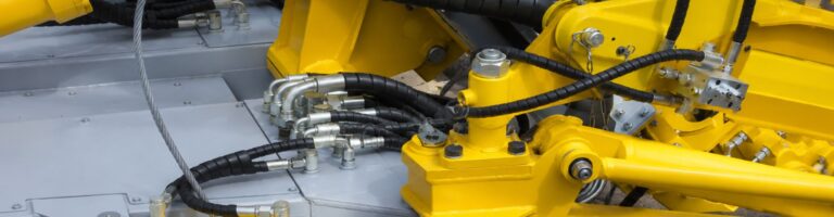
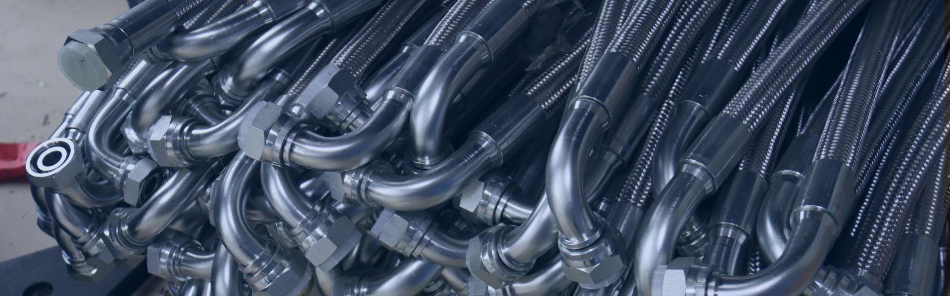
Metric hydraulic fittings are components specifically designed to connect various parts of a hydraulic system, ensuring a secure and leak-proof assembly. These fittings are measured in metric units (millimeters), aligning with the international standard of measurement used in many countries, especially across Europe and Asia. The primary purpose of these fittings is to maintain the integrity and efficiency of hydraulic systems by providing reliable connections that can withstand high pressure and adverse environmental conditions.
Hydraulic systems rely heavily on these fittings to function correctly. Without proper fittings, the hydraulic fluid could leak, leading to a loss in pressure and efficiency, and potentially causing system failure. Therefore, choosing the right type of hydraulic fitting is crucial for the overall performance and longevity of the system.
Metric vs Imperial Fittings
The primary difference between metric and imperial fittings lies in their measurement units. Metric fittings are measured in millimeters, while imperial fittings are measured in inches. This distinction is significant because it affects the compatibility of components within a hydraulic system.
Metric Fittings: Metric fittings are commonly used in systems designed and manufactured in countries that follow the metric system, such as those in Europe and Asia. These fittings are preferred for their precision and compatibility with international standards. They are often used in applications that require high accuracy and consistency in measurements.
Imperial Fittings: Imperial fittings are prevalent in the United States and other regions that use the imperial system. These fittings are measured in inches and fractions of inches, making them compatible with equipment and systems designed to imperial specifications. Imperial fittings are commonly found in North American industries, including automotive and aerospace.

Common Types of Metric Hydraulic Fittings
DIN (Deutsches Institut für Normung) Fittings
DIN fittings are standardized by the German Institute for Standardization (Deutsches Institut für Normung), ensuring a high level of precision and reliability. These fittings are widely utilized in European hydraulic systems due to their robust design and adherence to strict engineering standards. DIN fittings come in various styles, the most common being DIN 2353 and DIN 24°, each designed for specific applications and performance requirements.
DIN 2353 Fittings
DIN 2353 fittings are compression fittings designed for connecting hydraulic tubes. They are highly regarded for their ability to create leak-proof connections, even under high pressure. These fittings consist of a body, a ferrule, and a nut, which work together to form a secure connection. DIN 2353 fittings are available in three series, each defined by the tube’s outer diameter and wall thickness:
LL (Light Series): Suitable for low-pressure applications, often used in general industrial systems.
L (Light Series): Designed for medium-pressure applications, commonly found in automotive and industrial machinery.
S (Heavy Series): Built for high-pressure applications, typically used in heavy-duty industrial and mobile equipment.
DIN 24° Fittings
DIN 24° fittings, also known as flare fittings, are used extensively in hydraulic systems for their ability to handle high pressure and provide a secure, leak-free connection. These fittings feature a 24° cone and a sealing ring that ensures a tight seal. They are particularly valued for their robustness and are often used in critical applications where system integrity is paramount.

Key Characteristics
Precision Engineering: DIN fittings are manufactured with high precision, ensuring consistent quality and performance across different applications. The stringent manufacturing standards ensure that each fitting meets the exact specifications required for safe and efficient hydraulic system operation.
Versatility: DIN fittings are available in various configurations, including straight, elbow, tee, and cross fittings, catering to a wide range of hydraulic applications. This versatility makes them suitable for complex hydraulic circuits where multiple connections are needed.
High Pressure Capability: DIN fittings are designed to withstand high pressure, making them ideal for demanding hydraulic applications. Their robust construction ensures that they can handle the extreme conditions often encountered in industrial and mobile hydraulic systems.
Corrosion Resistance: Many DIN fittings are made from materials like stainless steel, providing excellent resistance to corrosion and extending the lifespan of the fittings in harsh environments.
Metric Parallel Thread (M Thread)
Metric Parallel Threads, also known as M Threads, have a constant diameter throughout the threaded portion, making them simple to manufacture and use. These threads are standardized and widely used in various applications, particularly where low-pressure and ease of manufacturing are key considerations.
International Standards
ISO 724:
This standard specifies the basic dimensions and tolerances for metric threads, ensuring consistency and interchangeability across different applications and manufacturers. ISO 724 outlines the thread profiles, including major and minor diameters, pitch, and thread angle, which are essential for proper mating and performance.
ISO 261:
ISO 261 covers the standard pitch and diameter combinations for metric threads, providing a comprehensive framework for selecting the appropriate thread size for various applications. This standard helps in maintaining uniformity and compatibility, crucial for the widespread use of M Threads in international markets.
Metric Tapered Threads
Metric Tapered Threads are conical in shape, designed to provide a tightening fit that enhances sealing capability. The tapering of the threads ensures that as the connection is tightened, the threads wedge together, creating a seal that becomes tighter with increased torque. This characteristic makes them particularly suited for high-pressure applications where robust and reliable sealing is critical.
Key Characteristics
Conical Shape:
The threads are designed with a taper, meaning the diameter of the thread decreases from one end to the other. This conical shape allows the threads to form a tight, pressure-resistant seal as they are screwed together
High-Pressure Capability:
Tapered threads are ideally suited for systems operating under high pressure. The design eliminates the need for secondary sealing methods, such as O-rings, by ensuring that the metal-to-metal contact is sufficient to prevent leaks even under high stress.
Excellent Sealing:
The self-sealing nature of tapered threads provides robust sealing without the need for additional components. This inherent sealing capability makes them highly reliable in applications where preventing leaks is paramount.
International Standards
ISO 7-1:
This standard specifies the dimensions and requirements for pipe threads where pressure-tight joints are made on the threads. ISO 7-1 ensures that metric tapered threads are manufactured to a consistent specification, facilitating their reliable use in high-pressure applications globally.
Metric O-Ring Face Seal
Metric O-Ring Face Seal fittings are designed with a flat face and an O-ring on the end. This design enhances the sealing capabilities of the fittings, making them highly reliable in preventing leaks. ORFS fittings are particularly known for their ability to handle high-pressure environments, ensuring zero-leakage performance even under extreme conditions.
International Standards
ISO 8434-3:
ISO 8434-3 specifies the dimensions, performance requirements, and testing methods for O-Ring Face Seal (ORFS) fittings. This standard ensures that ORFS fittings meet stringent quality and performance criteria, providing confidence in their use across different applications and industries.
Komatsu Metric Threads
Komatsu metric threads are specialized thread types used exclusively in Komatsu machinery. These threads differ slightly from standard metric threads and are designed to meet the unique hydraulic system requirements of Komatsu equipment. This specialization ensures optimal performance and compatibility with Komatsu’s construction and mining machinery.
Komatsu-Specific Standards
Komatsu uses proprietary standards for its metric threads to ensure high performance and reliability. These standards are tailored to meet the specific needs of Komatsu machinery, ensuring that all hydraulic components work together seamlessly. While these standards are proprietary, they align with general industry practices to ensure quality and reliability
Japanese Industrial Standard (JIS)

JIS metric threads, while not technically metric, share many similarities with metric threads and are often used in conjunction with standard metric fittings. They are primarily utilized in Japanese-made equipment, ensuring compatibility and performance in various industrial applications.
International Standards
JIS B 0203:
This standard covers the specifications for tapered threads used in hydraulic fittings, ensuring that JIS threads meet specific dimensional and performance criteria. It guarantees the reliability and compatibility of these threads in hydraulic applications.
JIS B 8363:
Specifies the requirements for hydraulic hose fittings, including dimensions, materials, and performance standards. This ensures that JIS hydraulic hose fittings provide reliable and efficient connections in various hydraulic systems.
Selecting the Right Metric Hydraulic Fittings
Selecting the appropriate metric hydraulic fittings is crucial for the efficient and safe operation of hydraulic systems. Here are the key factors to consider and guidance on application-based selection.
Factors to Consider
Pressure Ratings
Ensure that the fitting can withstand the maximum operating pressure of the hydraulic system. Using fittings with inadequate pressure ratings can lead to leaks or system failure under high-pressure conditions.
For example, DIN 2353 fittings are suitable for high-pressure applications, while M Threads are more appropriate for low-pressure systems.
Temperature Compatibility
Select fittings that can operate effectively within the temperature range of the system. High temperatures can affect the material properties and sealing capabilities of the fittings.
Stainless steel fittings are often preferred for high-temperature environments due to their superior thermal resistance.
Material Selection
Choose fittings made from materials that suit the application’s requirements. Common materials include:
Steel: High strength, suitable for high-pressure applications but prone to corrosion if not treated.
Stainless Steel: Offers high strength and excellent corrosion resistance, suitable for both high-pressure and corrosive environments.
Brass: Good corrosion resistance and easier to work with, but not suitable for high-pressure, high-temperature environments.

Sizing and Thread Type
Match the fitting size and thread type to the system specifications. Incorrect sizing or thread type can lead to leaks and mechanical failures.
Ensure compatibility with the system’s metric threads (e.g., DIN, JIS, Komatsu) to maintain the integrity of the hydraulic connections.
Application-Based Selection
Selecting the right fittings also depends on the specific hydraulic application. Here are some examples to illustrate how to choose appropriate fittings for different scenarios:
High-Pressure Applications:
For applications such as hydraulic presses or heavy machinery, use fittings with high-pressure ratings like DIN 2353 flareless fittings or Metric O-Ring Face Seal (ORFS) fittings. These fittings provide secure and leak-proof connections even under high stress.
Corrosive Environments:
In environments exposed to corrosive substances, such as marine or chemical processing industries, stainless steel fittings are ideal due to their excellent corrosion resistance. ORFS fittings in stainless steel provide a robust solution for leak-free performance.
General Industrial Use:
For general industrial machinery that operates under moderate pressure and temperature conditions, brass fittings can be an economical and effective choice. Metric Parallel Threads (M Threads) are suitable for these applications due to their simplicity and ease of use.
Automotive Systems:
In automotive applications, particularly in Japanese vehicles and machinery, JIS fittings are often required. These fittings ensure compatibility with Japanese standards and provide reliable performance in automotive hydraulic systems.
Conclusion
Choosing the right metric hydraulic fittings is fundamental for maintaining the efficiency, safety, and reliability of hydraulic systems. Understanding the specific requirements of pressure ratings, temperature compatibility, material selection, and correct sizing/thread types is essential. Proper installation and regular maintenance further enhance system longevity and prevent costly downtime and repairs, ensuring optimal performance across various applications. By adhering to these best practices, you can achieve robust and leak-free hydraulic connections, supporting seamless operations and minimizing operational disruptions.
FAQ
What are the main types of metric hydraulic fittings?
The main types include Metric Parallel Thread (M Thread), Metric Tapered Threads, Metric O-Ring Face Seal (ORFS), Flareless Threads (DIN 2353), Komatsu Metric Threads, and Japanese Industrial Standard (JIS) fittings. Each type has specific characteristics suited for different applications.
How do Metric Tapered Threads provide sealing?
Metric Tapered Threads have a conical shape that ensures a secure, tight fit, which improves sealing as the connection is tightened. This design eliminates the need for additional sealing methods such as O-rings, making them ideal for high-pressure applications.
What is the primary use of Metric O-Ring Face Seal fittings?
ORFS fittings are used for their high-pressure capability and zero-leakage performance. They feature a flat face with an O-ring that provides a leak-proof seal, making them ideal for hydraulic systems in heavy machinery and high-pressure fluid transfer applications.
Why are Flareless Threads (DIN 2353) fittings suitable for high-pressure applications?
DIN 2353 fittings use a metal-to-metal bite mechanism that creates a strong, leak-proof seal, making them excellent for medium to high-pressure applications. Their design eliminates the need for flaring the tubing, simplifying installation and enhancing reliability.
What distinguishes Komatsu Metric Threads from standard metric threads?
Komatsu Metric Threads are specifically designed for Komatsu machinery, ensuring compatibility and optimal performance with Komatsu’s hydraulic systems. They differ slightly from standard metric threads to meet the unique requirements of Komatsu’s equipment.
How do JIS metric threads differ from other metric threads?
JIS metric threads, while similar to standard metric threads, are primarily used in Japanese-made equipment. They offer compatibility with many standard metric fittings and are known for their durable design and excellent sealing properties, making them ideal for hydraulic systems in Japanese automotive and industrial machinery.


