What Are Brass Fittings Used For

What Are Brass Fittings Used For

What Are Brass Fittings Used For?

Table of Contents

Introduction

Brass fittings are essential components in various industries due to their durability, versatility, and corrosion resistance. This article delves into the numerous applications of brass fittings, exploring their benefits and why they are a preferred choice for many professionals.

Understanding Brass Fittings

Definition and Composition

Brass fittings are crucial components in plumbing, gas, HVAC, and various industrial systems. These fittings are primarily composed of an alloy of copper and zinc. The proportions of copper and zinc can vary, but typically brass consists of about 60-70% copper and 30-40% zinc. This combination of metals creates a material that possesses a unique balance of strength, malleability, and corrosion resistance, making it ideal for various applications.

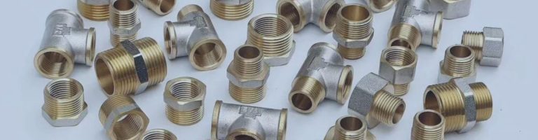
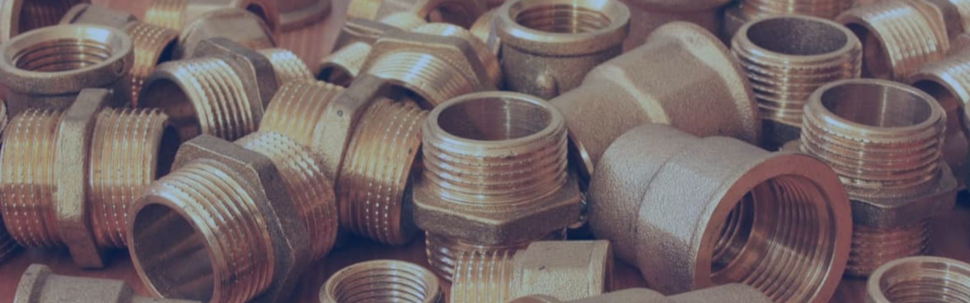
Types of Brass Fittings

Compression Fittings

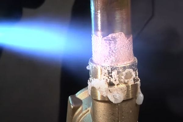
Compression fittings consist of a body, nut, and a compression ring or ferrule. When the nut is tightened, it compresses the ferrule against the pipe and the fitting body, creating a secure, leak-free seal.

Flare Fittings

Flare fittings have a conical end that matches a flared pipe end. The pipe is flared using a special tool, and the fitting is then screwed onto the flared end, creating a tight seal.

Threaded Fittings

Threaded fittings have male or female threads that screw onto matching pipe threads. They are available in various thread standards, including National Pipe Thread (NPT) and British Standard Pipe (BSP).

Push-to-Connect Fittings

Push-to-connect fittings, also known as push-fit or quick-connect fittings, feature an internal mechanism that grips the pipe when it is pushed into the fitting. These fittings often include a release mechanism to easily disconnect the pipe.

industrial brass fitting Topa

Advantages of Brass Fittings

Durability

Strength: Brass fittings are known for their strength and resilience. They can withstand high pressures and temperatures, making them suitable for a variety of demanding applications.

Longevity: The robust nature of brass ensures that fittings have a long lifespan, reducing the need for frequent replacements and maintenance.

Corrosion Resistance

Chemical Stability: Brass is highly resistant to corrosion and oxidation, which is essential for applications involving water, gas, and other potentially corrosive substances. This resistance extends the life of the fittings and maintains system integrity.

Environmental Resistance: Brass fittings perform well in a wide range of environmental conditions, from moist, humid environments to dry, arid climates, without degrading.

Adaptability

Compatibility with Various Materials: Brass fittings can be used with different types of piping, including copper, PVC, PEX, and more. This versatility makes them a go-to choice for many professionals across different industries.

Ease of Installation: The variety of brass fitting types means that there is a fitting solution for nearly every application. Whether it’s a quick-connect fitting for a rapid installation or a threaded fitting for a secure connection, brass fittings are designed to meet diverse needs.

Common Applications of Brass Fittings
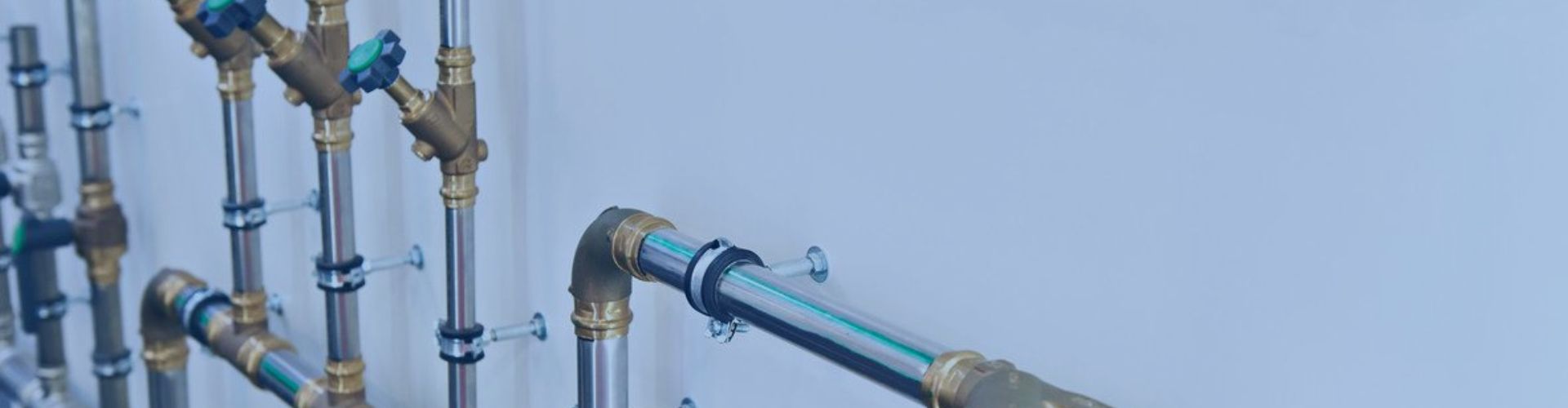
Plumbing Systems

plumbing system Brass fitting Topa

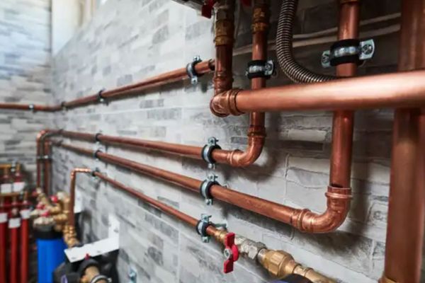
In residential plumbing, brass fittings are a preferred choice for water supply lines and hot water distribution due to their superior ability to withstand high temperatures and pressures. These fittings ensure a reliable, leak-free connection, which is crucial for maintaining the integrity of plumbing systems. Brass fittings are highly durable and can resist the common issues found in residential plumbing, such as pipe bursts and leaks, ensuring a long-lasting solution. They are used in various components, including faucets, showerheads, and pipe connectors.

In commercial plumbing, brass fittings are commonly found in public restrooms, commercial kitchens, and other high-traffic areas where durability and reliability are paramount. These fittings must endure frequent use and harsh cleaning chemicals, which can quickly wear down other materials. Brass fittings’ resistance to corrosion and physical wear makes them ideal for these demanding environments.

Gas Systems

Brass fittings are integral to natural gas and propane distribution systems, ensuring safety and efficiency. Their robustness and resistance to corrosion make them ideal for transporting gas safely. Gas systems require fittings that can handle significant pressure without degrading or leaking. Brass fittings are designed to prevent leaks and withstand the pressures involved in gas systems, making them a safe choice for both residential and commercial gas lines.

In residential settings, brass fittings are used in gas stove connections, gas heaters, and outdoor gas grills. They ensure a tight seal, preventing potentially dangerous gas leaks. In commercial settings, such as restaurants and industrial kitchens, brass fittings are used in larger gas distribution systems, ensuring that all gas appliances receive a consistent and safe supply of fuel.

HVAC Systems

In heating, ventilation, and air conditioning (HVAC) systems, brass fittings play a crucial role. They are used in various components, including condensers, evaporators, and refrigerant lines. The ability of brass fittings to handle high pressures and their resistance to corrosion contribute to the efficiency and reliability of HVAC systems.

Brass fittings are essential in maintaining the closed-loop systems required for efficient HVAC operation. They ensure that refrigerants are securely transported through the system without leaks, maintaining the system’s performance and preventing environmental contamination. In addition, brass fittings can handle the thermal expansion and contraction that occurs within HVAC systems, further enhancing their reliability.

Automotive Industry

In the automotive industry, brass fittings are used in critical components such as fuel lines, brake lines, and cooling systems. Their durability and resistance to wear make them suitable for these demanding applications. Brass fittings ensure secure connections and reliable performance under the high-stress conditions typical of automotive systems.

Fuel lines require fittings that can handle the constant flow of fuel without leaking, and brass fittings provide the necessary reliability. Brake lines use brass fittings to ensure that hydraulic brake fluid is efficiently and securely transported, ensuring the safety and responsiveness of the braking system. In cooling systems, brass fittings are used to connect various components, ensuring efficient heat dissipation and preventing overheating.

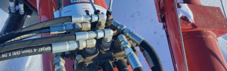
Manufacturing and Production

Brass fittings are extensively used in manufacturing and production environments, particularly in machinery and equipment that operate under high pressure. Their robustness and ability to maintain a tight seal under extreme conditions make them indispensable in these settings.

In manufacturing, brass fittings are used in hydraulic and pneumatic systems, ensuring that fluids and gases are transported efficiently and securely. They are also used in process equipment, such as reactors and mixers, where they provide reliable connections that can withstand the rigorous demands of industrial operations. Brass fittings’ resistance to corrosion ensures that they perform well even in environments with harsh chemicals and high temperatures.

Marine Applications

Marine Hydraulics Topa

In the boating and marine industries, brass fittings are favored for their resistance to saltwater corrosion. They are used in various applications, including fuel systems, water lines, and hydraulic systems. Brass fittings ensure reliability and longevity in the harsh marine environment.

In fuel systems, brass fittings are used to connect fuel lines to engines and tanks, ensuring a secure and leak-free connection. Water lines in boats also use brass fittings, as they can withstand the corrosive effects of saltwater and the constant motion of the vessel. Hydraulic systems, which control various functions such as steering and lifting, rely on brass fittings for their robustness and reliability. These fittings ensure that hydraulic fluid is efficiently transported to where it is needed, maintaining the performance and safety of marine operations.

Food and Beverage Industry

In the food and beverage industry, maintaining hygiene and ensuring the purity of products is paramount. Brass fittings are extensively used in various systems within this sector, particularly in beverage dispensing systems. Their unique properties make them well-suited for these applications, where both durability and cleanliness are critical.

One of the key advantages of brass fittings in the food and beverage industry is their exceptional resistance to corrosion. Beverage dispensing systems often involve liquids that can be acidic or contain other corrosive agents. Brass fittings withstand these conditions without degrading, ensuring the longevity of the system and reducing the need for frequent replacements.

Choosing the Right Brass Fitting for Your Needs

Selecting the appropriate brass fitting is essential for ensuring optimal performance, safety, and longevity of your systems. Here are the key factors to consider when choosing brass fittings, as well as an overview of common standards and certifications to ensure you make an informed decision.

Factors to Consider

Pressure and Temperature Ratings

Pressure Ratings: Brass fittings come with specific pressure ratings, indicating the maximum pressure they can safely handle. Ensure the fitting’s pressure rating matches or exceeds the system’s operating pressure to prevent leaks and failures.

Temperature Ratings: Similarly, fittings have temperature ratings indicating the maximum and minimum temperatures they can withstand. Choose fittings that can handle the operational temperature range of your system, especially in high-temperature applications like HVAC or coffee machines.

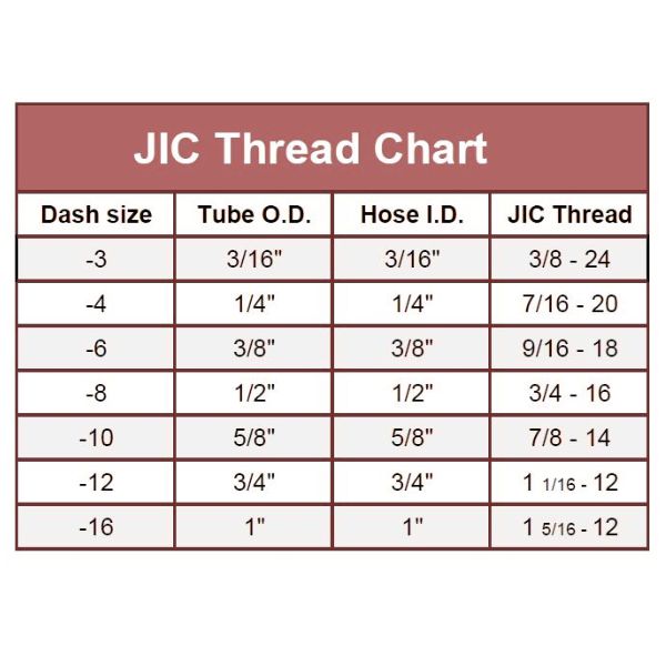
Size and Threading Specifications

Pipe Size Compatibility: Ensure the brass fitting is compatible with the size of the pipes or tubing in your system. This includes both the outer diameter (OD) and inner diameter (ID) specifications.

Thread Type and Size: Brass fittings are available in various thread types (e.g., NPT, BSP) and sizes. Verify that the threading on the fitting matches the threading on your pipes to ensure a secure connection. Proper threading is crucial to prevent leaks and ensure the system operates efficiently.

Material Quality

Brass Alloy Composition: Different brass alloys can offer varying levels of strength, flexibility, and corrosion resistance. Ensure that the brass alloy used in the fitting is suitable for your specific application, particularly in environments exposed to corrosive elements or high mechanical stress.

Installation Requirements

Ease of Installation: Consider how easy the fitting is to install. Some fittings, like push-to-connect types, offer quick and straightforward installation, while others, such as flare or compression fittings, may require specialized tools and skills.

Maintenance and Accessibility: Think about the long-term maintenance needs of the fitting. Fittings that are easy to access and maintain can save time and money in the long run.

Common Standards and Certifications

ANSI (American National Standards Institute)

Ensure the brass fittings comply with ANSI standards, which cover various aspects of fitting design, including dimensions, pressure ratings, and material specifications. ANSI standards ensure that the fittings meet rigorous quality and safety criteria, making them reliable for industrial use.

ISO (International Organization for Standardization)

Look for brass fittings that meet ISO standards. ISO certifications indicate that the fittings adhere to international benchmarks for quality, safety, and efficiency. ISO standards are widely recognized and ensure the fittings are suitable for global applications.

NSF (National Sanitation Foundation)

For applications in the food and beverage industry, ensure the brass fittings have NSF certification. This certification ensures that the fittings are safe for contact with consumable products and meet stringent hygiene and safety requirements.

ASTM (American Society for Testing and Materials)

ASTM standards specify the material and performance requirements for brass fittings. Compliance with ASTM standards ensures that the fittings are made from high-quality materials and are tested for performance and durability.

By considering these factors and ensuring compliance with relevant standards and certifications, you can select the right brass fitting for your specific needs. This careful selection process guarantees that the fittings will perform as expected, ensuring the safety, reliability, and efficiency of your systems.

Conclusion

Brass fittings are indispensable across various industries due to their durability, corrosion resistance, and versatility. They are essential in plumbing, gas systems, HVAC, automotive, manufacturing, marine, food and beverage sectors, and more. Choosing brass fittings ensures reliability, efficiency, and long-term performance in your applications. For those seeking robust, high-quality fittings, exploring brass options tailored to specific needs is highly recommended. Invest in brass fittings to enhance the safety and efficiency of your systems.

FAQ

Brass fittings are used in plumbing, gas systems, HVAC systems, automotive industry, manufacturing, marine applications, and the food and beverage industry due to their durability and corrosion resistance.

Yes, brass fittings are ideal for high-pressure applications as they can withstand significant pressure without leaking or failing.

Consider the application type, pressure and temperature ratings, size and threading specifications, and ensure the fitting complies with relevant standards and certifications like ANSI, ISO, or NSF.

Yes, brass fittings are compatible with various types of pipes, including copper, PVC, PEX, and stainless steel, making them versatile for different systems.

Brass fittings are highly resistant to corrosion, making them suitable for use in environments exposed to moisture, chemicals, and other corrosive elements.

Yes, brass fittings with NSF certification are safe for use in the food and beverage industry, ensuring hygiene and compliance with health standards.

What is BSP Thread

What is BSP Thread

What is BSP Thread?

Table of Contents

Introduction

British Standard Pipe (BSP) threads are a cornerstone of many industrial applications, playing a critical role in ensuring secure and leak-proof connections in a variety of systems. Originating in Britain, BSP threads have become a globally recognized standard, particularly in industries such as plumbing, gas, and hydraulics. Their design allows for tight, reliable seals, which are essential for maintaining the integrity and efficiency of piping and fitting assemblies. For professionals involved in these fields, a thorough understanding of BSP threads is not just beneficial but necessary. This knowledge ensures that installations are performed correctly, maintenance is effectively managed, and system failures are minimized.

Types of BSP Threads

BSPP

BSPP threads, also known as G threads, are parallel threads, meaning they maintain a constant diameter along their entire length. This design necessitates the use of a sealing washer or O-ring to create a leak-proof connection. The threads themselves do not provide the seal; instead, the seal is achieved through the compression of the washer or O-ring when the fitting is tightened.

BSPT

BSPT threads, also known as R threads, are tapered threads. This means the diameter of the thread decreases along its length, creating a conical shape. The tapering of the threads facilitates a tighter and more secure fit as the male and female threads are screwed together, deforming slightly to create a seal. This self-sealing property of BSPT threads eliminates the need for additional sealing components, relying instead on thread deformation to achieve a leak-proof connection.

Comparison between BSPP and BSPT

The primary difference between BSPP and BSPT threads lies in their shape: BSPP threads are parallel, maintaining a constant diameter, while BSPT threads are tapered, with the diameter decreasing along the length of the thread. This distinction influences how each type of thread achieves a seal. BSPP threads require additional sealing components such as washers or O-rings, whereas BSPT threads rely on the deformation of the threads themselves to create a seal.

Specific Use Cases:

BSPP: Ideal for low-pressure applications and situations where easy disassembly is required. Examples include hydraulic systems with frequent maintenance needs and pneumatic systems where precise alignment is critical.

BSPT: Preferred for high-pressure applications where a more secure seal is necessary. Examples include gas pipelines, high-pressure hydraulic systems, and other applications where the risk of leaks must be minimized and the connection must withstand significant pressure variations.

BSP Thread Standards and Specifications

BSP threads are governed by several key standards that ensure compatibility and reliability across various applications and industries.

BS 21:

BS 21 is the original British Standard for pipe threads, providing the foundational specifications for BSP threads. This standard encompasses both parallel and taper threads used in pipework and fittings. It ensures that threaded components are compatible and can form pressure-tight joints when needed.

ISO 228:

ISO 228 is an international standard that specifies the requirements for pipe threads where pressure-tight joints are not made on the threads. This standard applies primarily to BSPP (British Standard Pipe Parallel) threads. The focus here is on ensuring that threads maintain consistent dimensions and profiles, allowing for the use of sealing washers or O-rings to achieve a pressure-tight connection.

ISO 7:

ISO 7 outlines the specifications for pipe threads where pressure-tight joints are made on the threads themselves. This standard applies to BSPT (British Standard Pipe Taper) threads, which are designed to deform slightly when tightened to create a secure, leak-proof seal. ISO 7 ensures that the taper angle and thread profiles are consistent, providing reliable performance in high-pressure applications.

ISO BSP standard

Detailed Specifications for BSPP and BSPT

BSPP:

Defined by ISO 228: BSPP threads are parallel, maintaining a constant diameter along their length.

Thread Profile: The threads are designed with a 55-degree angle, consistent with the Whitworth thread form.

Sizes: BSPP thread sizes range from 1/16 inch to 6 inches, catering to a wide variety of applications in hydraulic, pneumatic, and plumbing systems.

BSPT:

Defined by ISO 7: BSPT threads are tapered, featuring a diameter that decreases along the length of the thread.

Taper Angle: The threads have a taper angle of 1:16, which helps in creating a tight seal as the threads are tightened.

Sizes: BSPT thread sizes also range from 1/16 inch to 6 inches, suitable for high-pressure applications such as gas pipelines and high-pressure hydraulic systems.

How to Identify BSP Threads

Visual Identification Techniques

Identifying BSP threads involves understanding their distinctive characteristics. BSP threads, whether BSPP (British Standard Pipe Parallel) or BSPT (British Standard Pipe Taper), feature a Whitworth thread profile, which is defined by a 55-degree thread angle. This unique profile sets BSP threads apart from other thread types, such as NPT (National Pipe Thread), which have a 60-degree thread angle.

BSPP Threads: These are parallel threads, meaning they maintain a constant diameter along their entire length. This characteristic makes them easy to identify visually as they do not taper and appear uniform from end to end.

BSPT Threads: These are tapered threads, where the diameter decreases along the length of the thread. When examining a BSPT thread, you’ll notice the tapering effect, which causes the thread to appear conical rather than cylindrical.

BSPT vs BSPP

Measuring Tools and Methods

Accurate identification often requires precise measurement tools:

Thread Gauge: A thread gauge is an essential tool for measuring the pitch of the threads. By matching the threads against the gauge, you can determine the number of threads per inch or the thread pitch in millimeters.

Calipers: These are used to measure both the outer diameter (OD) and inner diameter (ID) of the threads. For BSPP threads, the OD should be consistent along the length, whereas, for BSPT threads, the OD will decrease from one end to the other.

To measure:

Use the calipers to measure the OD at several points along the thread length. Consistency in measurement indicates BSPP, while a decrease in diameter suggests BSPT.

Use the thread gauge to check the thread pitch. Ensure the gauge fits snugly into the threads for an accurate reading.

Tightening the Fittings

Once the fittings are hand-tightened and properly aligned, use a wrench to tighten them further. Adjustable wrenches or pipe wrenches are suitable for this task. Be cautious not to over-tighten the fittings, as this can damage the threads and cause leaks. Tighten the fittings until they feel secure and snug. If you feel resistance indicating the threads are fully engaged, stop tightening to avoid damaging the fittings.

Interpreting Thread Markings and Labels

Thread markings and labels provide valuable information about the type and size of the thread. Typically, these markings include:

Thread Type: Indicated by letters such as “G” for BSPP threads and “R” for BSPT threads.

Thread Size: Usually noted after the thread type (e.g., G1/2, R3/4), indicating the nominal bore size of the pipe.

To ensure accurate identification:

Compare the markings with standard designations. For example, “G1/2” indicates a BSPP thread with a nominal bore of 1/2 inch, while “R3/4” indicates a BSPT thread with a nominal bore of 3/4 inch.

Confirm that the thread dimensions match the markings by measuring the pitch and diameter using the tools mentioned.

BSP Threads vs Other Thread Standards

Comparison with NPT Thread

NPT Threads:

Tapered with a 60-degree thread angle: NPT threads are designed with a taper and a 60-degree thread angle. The taper ensures that as the threads are tightened, they deform slightly to create a tight, leak-proof seal.

Primarily used in North America: NPT threads are widely adopted in the United States and Canada, serving as the standard for plumbing and pipe fittings in these regions.

Comparison:

Thread Angle and Pitch:

BSPT threads: These have a 55-degree thread angle and a unique pitch that differs from NPT threads. The slight difference in thread angle and pitch means BSPT and NPT threads are not interchangeable.

BSPP threads: These are parallel threads, maintaining a constant diameter along their length, unlike the tapered NPT threads. This fundamental difference in design affects how each type achieves a seal and their respective applications.

Usage and Compatibility:

BSPT vs NPT: While both BSPT and NPT threads are tapered and designed to form a seal through thread deformation, the different angles and pitches make them incompatible without specialized adapters.

BSPP: These threads require additional sealing components, such as O-rings or washers, unlike NPT threads, which rely on the thread taper to achieve sealing.

BSP vs NPT threads Topa

Comparison with Metric Threads

Metric Threads:

Defined by ISO 261 with a 60-degree thread angle: Metric threads follow the ISO 261 standard and feature a 60-degree thread angle. They are widely used in European machinery and manufacturing due to their standardized nature.

Commonly used in European machinery: Metric threads are the go-to choice for various applications across Europe, especially in the automotive and mechanical engineering sectors.

Comparison:

Thread Angle and Form:

BSP Threads: BSP threads have a 55-degree angle, differing from the 60-degree angle of metric threads. Additionally, the thread form of BSP threads is distinct, characterized by the Whitworth profile.

Sizing:

Metric Threads: These use the nominal outer diameter (OD) for sizing, providing a direct measurement of the thread’s external diameter.

BSP Threads: These use the nominal bore, which refers to the internal diameter of the pipe, not the thread’s outer diameter. This difference in sizing methodology can lead to confusion if not properly understood.

BSP Thread Installation and Maintenance

Best Practices for Installing BSP Threads

Proper installation of BSP threads is crucial for ensuring leak-free and reliable connections. Here are some best practices:

Ensure Clean and Undamaged Threads: Before starting the installation, inspect the threads for any dirt, debris, or damage. Clean the threads using a brush or cloth to remove any contaminants. Damaged threads should be repaired or replaced to prevent leaks and ensure a secure connection.

Use Appropriate Sealing Components for BSPP Threads: BSPP threads require sealing components like washers or O-rings to achieve a leak-proof connection. Ensure that these components are in good condition and compatible with the fluids being used in the system.

Common Tools and Equipment Required

Having the right tools and equipment is essential for the proper installation of BSP threads:

Wrenches: Adjustable wrenches or spanners are needed to tighten the fittings.

Thread Gauges: These are used to measure the thread pitch and ensure compatibility with other components.

Calipers: Useful for measuring the outer and inner diameters of the threads.

Sealant Tapes: PTFE (Polytetrafluoroethylene) tape or similar thread sealants are used for enhancing the sealing of BSPT threads.

Thread Sealant: For BSPT threads, applying thread sealant can help ensure a tight and leak-free seal. Choose a sealant that is compatible with the system’s fluids.

Tips for Ensuring Leak-Free Connections

To achieve a reliable and leak-free connection, follow these tips:

Tighten Threads to Manufacturer Specifications: Over-tightening can damage the threads or sealing components while under-tightening can result in leaks. Always follow the manufacturer’s torque specifications to ensure optimal tightness.

Use Thread Sealants Appropriately: For BSPT threads, apply an appropriate amount of thread sealant or PTFE tape. Wrap the tape in the direction of the threads to prevent it from unraveling during assembly.

Routine Maintenance and Troubleshooting

Regular maintenance is vital for the longevity and reliability of BSP threaded connections:

Regularly Inspect Connections: Periodically check the connections for signs of wear, corrosion, or damage. Look for any leaks or signs of fluid seepage.

Replace Worn-Out Sealing Components: Washers, O-rings, and other sealing components can degrade over time. Replace them promptly to maintain the integrity of the connection.

Check for Leaks and Retighten or Reseal as Necessary: If leaks are detected, identify the source and address it immediately. Retighten the connections to the specified torque or reapply the thread sealant if necessary.

By following these best practices and maintenance tips, you can ensure that BSP threaded connections remain secure, leak-free, and reliable throughout their service life. Proper installation and regular maintenance not only enhance the performance of the system but also prevent costly downtimes and repairs.

Conclusion

In summary, BSP threads are a vital component in various industrial applications, offering reliable and standardized pipe connections. Understanding the differences between BSPP and BSPT, recognizing the relevant standards, and knowing how to identify and install these threads are essential skills for professionals in the field. For further reading and exploration, consult additional resources and industry standards to deepen your knowledge and expertise.

FAQ

BSP stands for British Standard Pipe. It refers to a family of standard screw threads used internationally for interconnecting and sealing pipes and fittings.

BSPP threads are parallel and require sealing components like washers or O-rings, while BSPT threads are tapered and achieve sealing through thread deformation.

BSPP and BSPT threads are not typically used together due to their different sealing mechanisms. BSPP threads require a sealing component, whereas BSPT threads rely on the taper for sealing.

BSP threads have a 55-degree Whitworth profile. BSPP threads maintain a constant diameter along their length, while BSPT threads taper. Thread markings, such as “G” for BSPP and “R” for BSPT, and measurements with thread gauges can also help in identification.

BSP threads are not compatible with NPT (National Pipe Thread) threads due to differences in thread angle (55 degrees for BSP, 60 degrees for NPT) and pitch. Special adapters are required to connect BSP and NPT threads.

Essential tools for installing BSP threads include adjustable wrenches or spanners, thread gauges, calipers, PTFE tape or thread sealant (for BSPT threads), and sealing components like washers or O-rings (for BSPP threads).

What Does JIC Mean in Hydraulic Fittings

What Does JIC Mean in Hydraulic Fittings?

What Does JIC Mean in Hydraulic Fittings?

Table of Contents

Introduction

Hydraulic systems rely heavily on various components to function efficiently, and one of these crucial components is hydraulic fittings. Understanding the different types of fittings available is essential for ensuring the reliability and safety of hydraulic systems. This article aims to delve into what JIC means in hydraulic fittings, exploring their design, applications, advantages, and more.

Introduction to JIC Fittings

What Does JIC Stand For?

JIC stands for Joint Industry Council, an organization that was pivotal in developing standards for hydraulic connectors. This council’s primary goal was to create a standardized fitting that could be used across various industries, ensuring uniformity and compatibility.

JIC 74° Topa

The 37-degree Flare Seating Surface

One of the defining characteristics of JIC fittings is their 37-degree flare seating surface. This specific angle is critical because it ensures a tight seal between the fitting and the hydraulic hose or tube. The flare design allows the metal surfaces to mate perfectly when the fitting is assembled, creating a robust and leak-proof connection. The 37-degree angle was chosen after extensive testing and research, proving to be the optimal angle for durability and performance under high pressure.

Ensuring Compatibility and Interchangeability

JIC fittings were designed with compatibility and interchangeability in mind. This means that a JIC fitting from one manufacturer will fit and function correctly with a JIC fitting from another manufacturer, as long as both adhere to the standard specifications. This interchangeability reduces downtime in operations, as replacements and repairs can be made quickly without worrying about sourcing specific brands or custom parts.

Popularity and Applications of JIC Fittings

The standardization and reliability of JIC fittings have made them a popular choice in many applications. They are widely used in hydraulic systems across various sectors, including agriculture, construction, automotive, and oil and gas. Their ability to provide secure, leak-proof connections under high pressure makes them ideal for demanding environments. The versatility of JIC fittings also means they can be used in both stationary and mobile equipment, further broadening their application range.

Technical Specifications of JIC Fittings

Material Composition

JIC fittings are manufactured from a range of durable materials, each chosen for their specific properties that enhance the fitting’s performance:

Stainless Steel: Known for its excellent corrosion resistance and high strength, stainless steel JIC fittings are ideal for applications involving harsh environments or where hygiene is a concern, such as in the food and beverage or chemical industries.

Brass: Brass fittings offer good corrosion resistance and are easy to machine, making them a cost-effective choice for many standard hydraulic applications. They are often used in low to medium-pressure systems where durability and ease of installation are prioritized.

Carbon Steel: Carbon steel fittings are renowned for their high strength and toughness, making them suitable for high-pressure applications. They are often coated or plated to enhance their corrosion resistance, ensuring longevity in demanding conditions.

Pressure Tolerance

JIC fittings are designed to withstand high-pressure conditions, a critical requirement in hydraulic systems. The exact pressure tolerance can vary depending on the material and size of the fitting, but generally, JIC fittings are rated for pressures up to 10,000 psi or more. This high-pressure tolerance ensures that the fittings can handle the demands of various hydraulic applications without failing.

Size Variations

JIC fittings are available in a wide range of sizes to accommodate different hose and tube diameters. Common sizes include 1/8″, 1/4″, 3/8″, 1/2″, 3/4″, and 1″, among others. This variety ensures that there is a JIC fitting suitable for almost any hydraulic system requirement, providing flexibility in system design and maintenance.

Hydraulic Fitting Sizes JIC thread

Compliance with Standards

JIC fittings conform to rigorous standards, ensuring their performance and safety:

SAE J514: This standard, developed by the Society of Automotive Engineers (SAE), specifies the dimensions, performance, and testing requirements for 37-degree flare fittings. Compliance with SAE J514 ensures that JIC fittings are compatible with other fittings and components made to the same standard, facilitating easy integration and replacement.

ISO 8434-2: The International Organization for Standardization (ISO) standard 8434-2 covers the general and dimensional requirements for 37-degree flare fittings. Adherence to this standard guarantees that the fittings meet international quality and safety benchmarks, making them suitable for global applications.

JIC Fittings Compared to Other Standards

When working with hydraulic systems globally, understanding the differences between JIC fittings and other international standards is crucial for proper system design, maintenance, and component selection. This comparison highlights the key differences in design, application, and compatibility between JIC and other major hydraulic fitting standards.

JIC vs Metric Fittings

Sealing Mechanism

JIC Fittings: Utilize a 37° flared sealing surface where metal-to-metal contact creates the seal. The male fitting has a 37° cone that mates with the female 37° flare.

Metric Fittings: Typically employ a 24° cone sealing system (DIN 2353/ISO 8434-1) where the cutting ring or ferrule creates two sealing points between the fitting body and tube.

Thread Type

JIC Fittings: Use Unified National Fine (UNF) threads with a straight (parallel) thread form measured in inches.

Metric Fittings: Use metric straight threads measured in millimeters with standardized pitch (e.g., M14×1.5, M16×1.5).

Size Designation

JIC Fittings: Sized by dash numbers representing 1/16-inch increments (e.g., -4 equals 4/16 or 1/4 inch).

Metric Fittings: Directly designated by their nominal outer diameter in millimeters (e.g., 6mm, 8mm, 10mm).

Pressure Ratings

JIC Fittings: Generally rated for medium to high-pressure applications, typically up to 5,000-6,000 PSI depending on size.

Metric Fittings: Available in light (L), heavy (S), and very heavy (LL) series with pressure ratings from 3,600 PSI to over 9,000 PSI depending on the series and size.

Global Adoption

JIC Fittings: Predominantly used in North America and in industries with American origins.

Metric Fittings: Standard throughout Europe, Asia, and most developing markets.

hydraulic JIC fittings banner Topa China

JIC vs British Standard Pipe (BSP)

Sealing Mechanism

JIC Fittings: 37° metal-to-metal flare seal.

BSPP Fittings: Parallel thread (G) that requires a bonded seal, O-ring, or other sealing element compressed against a 30° chamfer or flat face.

BSPT Fittings: Tapered thread (R) that creates a seal through thread deformation, often requiring thread sealant.

Thread Form

JIC Fittings: 60° thread angle with UNF thread form.

BSP Fittings: 55° Whitworth thread form with rounded roots and crests, giving a distinctive appearance.

Size Designation

JIC Fittings: Dash number system based on 1/16-inch increments.

BSP Fittings: Nominal pipe sizes in inches (e.g., 1/4″, 1/2″), which don’t directly correspond to actual thread dimensions.

Applications

JIC Fittings: Common in mobile hydraulics, industrial machinery, and aerospace applications.

BSP Fittings: Prevalent in European hydraulic systems, Commonwealth countries, and marine applications.

Interchangeability

JIC and BSP fittings are not interchangeable despite some having similar dimensions. For example, a 9/16″-18 JIC thread and G 1/4 BSPP have close dimensions but different thread forms and sealing methods.

JIC vs NPT (National Pipe Thread)

JIC vs NPT vs BSP

Sealing Mechanism

JIC Fittings: 37° flare with metal-to-metal contact.

NPT Fittings: Tapered thread that creates a seal through thread deformation, typically requiring PTFE tape or liquid thread sealant.

Thread Type

JIC Fittings: Straight UNF threads that don’t participate in sealing.

NPT Fittings: Tapered threads with a 1° 47′ taper angle that creates the seal throughan interference fit.

Reusability

JIC Fittings: Can be disconnected and reconnected multiple times without significant degradation of the sealing surface.

NPT Fittings: Each assembly/disassembly cycle can degrade the sealing capability, making them less ideal for systems requiring frequent maintenance.

Pressure Consistency

JIC Fittings: Provide consistent pressure ratings and predictable torque requirements.

NPT Fittings: Sealing effectiveness can vary based on installation technique and thread sealant application.

JIC vs SAE Straight Thread O-Ring (STOR)

Sealing Mechanism

JIC Fittings: 37° flare metal-to-metal seal.

SAE STOR Fittings: O-ring compressed in a gland to create the seal, with straight threads only providing mechanical connection.

Pressure Capability

JIC Fittings: Good for medium to high-pressure applications.

SAE STOR Fittings: Excellent for high-pressure applications with superior vibration resistance due to the elastomeric seal.

Assembly Considerations

JIC Fittings: Require proper torque to ensure the flare seats correctly without over-tightening.

SAE STOR Fittings: Require careful O-ring installation and prevention of damage during assembly.

Common Applications

JIC Fittings: Widely used across various hydraulic applications.

SAE STOR Fittings: Common in mobile equipment where vibration resistance is critical.

Feature

JIC

Metric

BSP

NPT

SAE STOR

Sealing Method

37° flare metal-to-metal

24° cone with cutting ring

BSPP: Bonded seal/O-ring BSPT: Thread deformation

Thread deformation with sealant

O-ring compression

Thread Type

Straight UNF threads

Straight metric threads

55° Whitworth thread form

Tapered 1°47′ threads

Straight UNF threads

Thread Angle

60°

60°

55°

60°

60°

Size Designation

Dash numbers (-4 = 1/4″)

Millimeters (6mm, 8mm)

Inch fractions (1/4″, 1/2″)

Inch fractions (1/4″, 1/2″)

Dash numbers

How to Identify JIC Fittings

Identifying JIC fittings accurately is crucial for ensuring compatibility and proper functioning within hydraulic systems. This section provides detailed guidance on visual identification tips, measuring techniques, and common mistakes to avoid.

Visual Identification Tips

Markings on the Fittings

JIC fittings often have specific markings that help identify their type and size. These markings can include:

Manufacturer’s Name or Logo: This helps trace the origin of the fitting.

Size Designation: Typically marked in inches or fractions of an inch, indicating the fitting size.

Standards Compliance: Marks indicating compliance with standards such as SAE J514 or ISO 8434-2.

Flare Angle

The most distinctive feature of JIC fittings is the 37-degree flare angle. This angle is critical for identification and can often be recognized visually by those familiar with hydraulic fittings. The flare angle ensures a proper metal-to-metal seal, distinguishing JIC fittings from other types, such as SAE 45-degree fittings.

Shape and Construction

JIC fittings have a unique shape due to their flare design. They typically consist of a body, sleeve, and nut. The fitting’s body will have a conical surface designed to mate with the 37-degree flared tube. Familiarity with the overall shape and construction can aid in quick identification.

hydraulic JIC fittings banner Topa China

Measuring Techniques for Accurate Identification

Using a Caliper

A caliper is an essential tool for measuring the critical dimensions of JIC fittings:

Outer Diameter (OD): Measure the OD of the fitting to determine its size.

Flare Diameter: Measure the diameter of the flared end of the tube or fitting.

Thread Pitch: Use a thread pitch gauge to measure the threads per inch (TPI) or the distance between threads. This helps differentiate JIC threads from other thread types.

Using a Protractor or Flare Gauge

To measure the flare angle accurately:

  • Place the protractor or flare gauge against the flared surface.
  • Ensure the tool matches the 37-degree angle precisely.
  • Any deviation indicates the fitting may not be a JIC fitting.

Common Mistakes and How to Avoid Them

Misidentifying Flare Angles

One of the most common mistakes is confusing JIC fittings with other flare fittings, such as SAE 45-degree fittings. To avoid this:

  • Always use a protractor or flare gauge to confirm the 37-degree angle.
  • Familiarize yourself with the visual differences between 37-degree and 45-degree flares.

Ignoring Thread Pitch

JIC fittings have specific thread pitches that must be matched correctly. Mistaking thread pitches can lead to incompatible connections. Use a thread pitch gauge to measure and match the correct pitch accurately.

Overlooking Markings

Markings on fittings provide valuable information about their size and compliance. Ignoring these can lead to incorrect identification. Always check for and interpret these markings correctly.

Not Measuring Properly

Relying on visual identification alone without precise measurement can result in errors. Always use appropriate tools like calipers, protractors, and thread pitch gauges to ensure accurate identification.

Installation and Maintenance of JIC Fittings

Proper installation and maintenance of JIC fittings are essential for ensuring secure, leak-free connections in hydraulic systems. This section provides a detailed guide on the installation process and essential maintenance practices.

Installation of JIC Fittings

Cutting the Tube

  • Measure and Mark: Measure the tube to the required length and mark the cutting point.
  • Cut the Tube: Use a tube cutter to ensure a clean, square cut. Avoid using saws that may leave burrs or deform the tube.
  • Deburr the Edges: After cutting, remove any burrs from the tube ends using a deburring tool. This step is crucial to ensure a smooth, even surface for flaring.

Creating a 37Degree Flare

  • Select the Right Flaring Tool: Use a flaring tool specifically designed for 37-degree JIC fittings. Prepare the Tool: Follow the manufacturer’s instructions to set up the flaring tool correctly.
  • Insert the Tube: Place the tube end into the flaring tool and secure it firmly.
  • Create the Flare: Operate the flaring tool to form the 37-degree flare on the tube end. Ensure the flare is uniform and free of cracks or distortions.

Assembling the Fitting

  • Slide on the Nut and Sleeve: Before flaring, slide the fitting nut and sleeve onto the tube. The sleeve should sit just behind the flared end.
  • Align the Flare with the Fitting: Insert the flared tube end into the fitting body, ensuring the flare sits snugly against the fitting’s conical surface.
  • HandTighten the Nut: Initially, handtighten the nut to keep the components aligned.

Final Tightening

  • Use a Torque Wrench: To avoid overtightening or under tightening, use a torque wrench set to the manufacturer’s recommended torque specifications.
  • Tighten the Nut: Gradually tighten the nut while holding the fitting body steady with a backup wrench. Follow a consistent and even tightening pattern.
  • Check Alignment: Ensure the flare remains properly seated during tightening to avoid misalignment and potential leaks.

Maintenance of JIC Fittings

Regular Inspections

  • Visual Inspection: Regularly inspect JIC fittings for signs of wear, corrosion, or damage. Look for visible leaks or fluid residue around the fitting.
  • Check for Tightness: Periodically check the tightness of the fittings. Loose fittings can lead to leaks and should be retightened to the specified torque.

Leak Detection

  • Use Leak Detection Fluid: Apply a leak detection fluid around the fitting joints to identify any leaks. Bubbles forming indicate a leak.
  • Monitor System Pressure: Sudden drops in system pressure can indicate a leak in the fittings.

Preventive Maintenance

  • Replace Worn Components: Replace any components showing signs of wear or damage, including the fitting body, nut, or sleeve.
  • Re-Flare Damaged Tubes: If the tube flare is damaged or distorted, cut off the damaged section and reflare the tube end.
  • Lubrication: Apply a light coating of hydraulic oil to the threads before reassembly to facilitate easier tightening and prevent galling.

Documentation

  • Maintain Records: Keep detailed records of maintenance activities, including inspection dates, findings, and any replacements or repairs performed. This helps track the performance and reliability of the fittings over time.

Proper installation and regular maintenance of JIC fittings are critical for ensuring reliable, leakfree hydraulic connections. Following the correct procedures for cutting, flaring, and assembling the fittings, and adhering to a routine maintenance schedule, will extend the life of the fittings and maintain the efficiency and safety of the hydraulic system. These practices help prevent unexpected failures and costly downtime, ensuring optimal performance in demanding applications.

Conclusion

In summary, understanding the functionality and benefits of JIC fittings is critical for anyone working with hydraulic systems. Their reliable sealing mechanism, highpressure tolerance, and versatility make them an indispensable component in various industries. By choosing the appropriate fittings and adhering to proper installation and maintenance protocols, users can ensure that their hydraulic systems remain efficient, reliable, and longlasting.

FAQ

JIC stands for Joint Industry Council. These fittings are known for their 37degree flare design, which ensures a reliable, leakproof connection in hydraulic systems.

The main advantages of JIC fittings include their highpressure tolerance, reliable metaltometal seal, ease of assembly and disassembly, versatility in various applications, and reusability.

JIC fittings can be identified by their 37degree flare angle, specific markings indicating size and standards compliance, and their unique shape and construction. Using a protractor or flare gauge can help confirm the 37degree angle.

JIC fittings are typically made from stainless steel, brass, or carbon steel. These materials are chosen for their durability, corrosion resistance, and ability to withstand high pressures.

JIC fittings conform to standards such as SAE J514 and ISO 84342. These standards ensure that the fittings meet specific performance and safety requirements, guaranteeing compatibility and reliability.

Regular maintenance of JIC fittings includes visual inspections for wear and tear, checking for leaks, ensuring proper tightness.

How to Solder Copper Pipe to Brass fitting

How to Solder Copper Pipe to Brass Fitting

How to Solder Copper Pipe to Brass Fitting

Introduction

Soldering copper pipe to brass fittings is a critical skill in the fields of plumbing and HVAC (heating, ventilation, and air conditioning). The goal of this post is to provide a comprehensive, step-by-step guide on how to effectively solder copper pipe to brass fittings.

Understanding the Basics

Before diving into the soldering process, it’s crucial to gather all the necessary materials and tools. Having everything at hand will ensure a smooth and efficient workflow, minimizing interruptions and enhancing safety. Here’s a comprehensive list of what you’ll need:

Materials

Copper Pipe: The primary material for the pipe sections of your project. Choose the correct diameter and length for your specific needs.

Brass Fitting: Used to connect different sections of copper pipe or to join copper pipe to other types of pipe. Brass fittings are available in various configurations such as elbows, tees, and couplings.

Lead-Free Solder: Essential for creating a strong and safe bond. Lead-free solder is particularly important for potable water systems to prevent lead contamination.

Flux: A chemical cleaning agent that helps the solder flow and bond properly by cleaning the metal surfaces and preventing oxidation.

Emery Cloth or Sandpaper: Used to clean and prepare the surfaces of the copper pipe and brass fitting, ensuring a good bond.

Pipe Cleaning Brush: A cylindrical brush designed to clean the inside of copper pipes and fittings.

Tools

flux

Pipe Cutter: A specialized tool for cutting copper pipes cleanly and accurately. Ensure it’s sharp and in good condition for the best results.

Torch: A propane or MAPP gas torch is used to heat the joint to the correct temperature for soldering. The torch should have a precise flame control feature.

Safety Gear: Includes heat-resistant gloves, safety goggles, and a long-sleeve shirt to protect against burns and splashes.

Heat Shield: A protective barrier to shield surrounding areas from the torch’s flame, preventing accidental fire hazards.

Adjustable Wrenches: For holding and adjusting the fittings securely during the soldering process.

Tape Measure: To measure the length of the copper pipe accurately before cutting.

Marker or Pencil: For marking cutting lines on the copper pipe.

Deburring Tool: Used to remove burrs from the cut end of the pipe, ensuring a smooth, clean edge.

Why Solder Copper to Brass?

Copper and brass are highly valued in plumbing and HVAC systems due to their distinct and complementary properties.

Corrosion Resistance

Copper and brass are both highly resistant to corrosion, which is essential for long-lasting plumbing and HVAC systems. This resistance ensures that the pipes and fittings maintain their integrity and functionality over time, reducing the likelihood of leaks and system failures.

Thermal Conductivity

Copper has excellent thermal conductivity, making it an ideal material for heating and cooling applications. This property allows for efficient heat transfer.

Strength and Durability

Brass fittings offer superior strength and durability, capable of withstanding high pressure and temperature variations. This makes brass an excellent choice for connections that require a robust and reliable seal.

Step-by-Step Guide to Soldering Copper Pipe to Brass Fitting

Preparation

Safety First

Safety is paramount when working with tools and materials that involve high heat and potentially hazardous substances. Here are essential safety tips to follow:

  • Wear Safety Gear: Always wear heat-resistant gloves to protect your hands from burns. Safety goggles are crucial to shield your eyes from sparks, debris, and harmful fumes. Long-sleeved shirts and long pants made of non-flammable materials will protect your skin.
  • Work in a Well-Ventilated Area: Ensure that your workspace is well-ventilated to avoid inhaling harmful fumes produced during the soldering process. If working indoors, use a fan or an exhaust hood to improve ventilation.
  • Fire Safety: Keep a fire extinguisher nearby and be aware of its location and how to use it. Clear the area of any flammable materials and use a heat shield to protect walls and other surfaces from the torch’s flame.
  • Proper Lighting: Make sure your work area is well-lit so you can clearly see the joint and ensure precise application of heat and solder.

Cutting the Copper Pipe

Accurate measurement and clean cuts are essential for a successful soldering job. Follow these steps to measure and cut the copper pipe:

  • Measure the Pipe: Use a tape measure to determine the required length of the copper pipe. Mark the measurement with a pencil or marker.
  • Cut the Pipe: Use a pipe cutter for a clean, straight cut. Position the cutter on the mark, tighten the blade, and rotate the cutter around the pipe. Gradually tighten the blade after each full rotation until the pipe is cut through.
  • Deburr the Pipe: After cutting, use a deburring tool to remove any burrs from the cut end of the pipe. Burrs can impede the fitting process and affect the integrity of the joint.

Cleaning the Pipe and Fitting

Proper cleaning ensures that the solder bonds effectively to the copper pipe and brass fitting:

  • Clean the Pipe: Use an emery cloth or sandpaper to clean the outside of the copper pipe’s end. Rub the cloth or sandpaper around the pipe until it is shiny and free of oxidation and debris.
  • Clean the Fitting: Similarly, clean the inside of the brass fitting using an emery cloth or a pipe cleaning brush. Make sure all surfaces to be joined are clean and shiny.

Applying Flux

  • Choosing the Right Flux
  • Flux is essential in the soldering process as it helps the solder flow and bond by cleaning the metal surfaces and preventing oxidation:
  • Types of Flux: There are several types of flux available, including water-soluble, petroleum-based, and rosin-based flux. For plumbing applications, a water-soluble flux is often recommended as it is easy to clean after soldering.
  • Best Flux for the Job: Choose a flux specifically designed for plumbing or HVAC work, which is typically safe for potable water systems and compatible with both copper and brass.

Applying the Flux

Proper application of flux is critical to ensure a strong bond:

  • Apply Flux to the Pipe: Use a small brush to apply a thin, even layer of flux to the cleaned end of the copper pipe. Ensure the entire surface that will be inserted into the fitting is covered.
  • Apply Flux to the Fitting: Similarly, apply a thin layer of flux to the inside of the brass fitting where it will contact the pipe. This will ensure both surfaces are properly prepared for soldering.

Fitting the Pieces Together

Inserting the Copper Pipe into the Brass Fitting

Ensuring a snug fit without forcing the pieces is key to a successful joint:

  • Align the Pipe and Fitting: Carefully insert the flux-coated end of the copper pipe into the brass fitting. Rotate the pipe slightly as you push it in to ensure the flux is evenly distributed and the fit is secure.
  • Check the Fit: Make sure the pipe and fitting are aligned correctly and that the pipe is fully seated in the fitting. There should be no gaps between the surfaces to be soldered.
welding brass to copper

Soldering the Joint

Heating the Joint

Proper heating is crucial for a strong, leak-free joint:

  • Prepare the Torch: Light your propane or MAPP gas torch and adjust it to a medium flame with a sharp, blue cone for precise heating.
  • Heat the Joint Evenly: Begin heating the joint by moving the torch flame around the pipe and fitting it to distribute heat evenly. Avoid overheating any one spot to prevent burning the flux.
  • Heat Until Flux Sizzles: Heat the joint until the flux begins to sizzle and bubble, indicating that the metal is hot enough for soldering.

Applying the Solder

Applying solder at the right moment ensures a secure bond:

  • Apply the Solder: Once the joint is sufficiently heated, touch the tip of the solder wire to the joint. The heat will draw the solder into the gap between the pipe and the fitting through capillary action.
  • Continue Heating: Move the torch as needed to keep the joint hot enough for the solder to flow smoothly and evenly around the joint. Ensure the entire circumference of the joint is covered with solder.
  • Remove Excess Solder: Once the joint is filled, remove the solder and the torch. Allow any excess solder to drip off or wipe it away carefully with a rag.

Allowing the Joint to Cool

Letting the joint cool properly ensures the solder solidifies correctly:

  • Natural Cooling: Allow the joint to cool naturally without disturbing it. Do not touch or move the pipe and fitting until the solder has fully solidified.
  • Inspect the Joint: Once cool, inspect the joint for any gaps or inconsistencies in the solder. A smooth, shiny appearance indicates a good bond.

Troubleshooting Common Issues

Cold Joints

Identifying Cold Joints:

Cold joints occur when the solder does not melt properly or does not adhere correctly to the pipe and fitting, resulting in a weak, unreliable connection. Identifying cold joints is crucial to ensure the integrity of your plumbing or HVAC system.

  • Visual Inspection: A cold joint often appears dull, rough, and uneven compared to a properly soldered joint, which should be smooth and shiny.
  • Physical Test: Cold joints may feel loose or show signs of movement when slight pressure is applied. A properly soldered joint should be solid and immovable.
  • Performance Issues: Cold joints can lead to leaks or reduced system efficiency due to the incomplete bonding of the materials.

Fixing Cold Joints:

  • Reheat the Joint: Carefully reheat the joint with your torch, ensuring that the entire area reaches the appropriate temperature for the solder to melt and flow properly.
  • Apply More Flux: If necessary, add a small amount of flux to the joint to improve the flow of the solder and ensure proper bonding.
  • Add Solder: Apply additional solder to fill any gaps and create a smooth, even joint. Ensure the solder is drawn into the joint by capillary action.
  • Allow to Cool: Let the joint cool naturally without disturbing it. Inspect the joint again to ensure it has a shiny, smooth appearance and is securely bonded.
hot welding

Improper Thread Sealant Application

Too Much Thread Sealant

Applying too much thread sealant, whether Teflon tape or pipe dope, can interfere with the threading process. Excessive sealant can prevent the threads from fully engaging, leading to leaks or weakened connections.

  • Solution: Apply Teflon tape by wrapping it around the male threads two to three times, ensuring even coverage without overwrapping. For pipe dope, use a small brush or applicator to spread an even layer on the threads, avoiding clumps or excess.

Too Little Thread Sealant

Applying too little thread sealant can leave gaps in the threads, allowing fluids or gases to escape. Inadequate coverage fails to create a proper seal, making leaks more likely.

  • Solution: Ensure that the sealant covers all the threads evenly. For Teflon tape, wrap it tightly and ensure it adheres smoothly to the threads. For pipe dope, spread it uniformly with no gaps or missed spots.

Incorrect Pipe Alignment

Misaligned pipes can place undue stress on the fittings, leading to leaks and potential damage. Pipes that are not properly aligned can cause fittings to warp or fail, compromising the entire system.

  • Solution: Before tightening, ensure the pipes are correctly aligned. Hand-tighten the fittings to check for alignment, making any necessary adjustments before using a wrench. Proper alignment reduces stress on the fittings and ensures a secure connection.

Excessive Solder

Excessive solder can create problems such as blockages inside pipes, unsightly joints, and potential weak points. Here’s how to manage and prevent it:

  • Apply Solder Sparingly: When soldering, use just enough solder to fill the joint. Too much solder can lead to drips and uneven distribution.
  • Control the Heat: Overheating can cause the solder to flow excessively. Ensure the torch is set to the appropriate temperature and move it evenly around the joint.
  • Positioning: Position the pipe and fitting horizontally or at a slight angle to control the flow of the solder and prevent it from pooling in one area.

Fixing Excessive Solder:

  • Reheat the Joint: Gently reheat the joint with your torch to soften the excess solder.
  • Remove Excess Solder: Use a clean, heat-resistant cloth to wipe away the softened excess solder. Be careful to avoid disturbing the joint itself.
  • Inspect the Joint: Ensure the joint is smooth and free of excessive solder. If necessary, reapply a small amount of solder to fill any gaps created during the removal process.

Leaky Joints

Diagnosing Leaky Joints:

Leaky joints can compromise the efficiency and safety of your plumbing or HVAC system. Identifying and diagnosing the cause of leaks is essential:

  • Visual Inspection: Look for signs of moisture or water droplets around the joint. Leaky joints may show visible signs of water seepage.
  • Pressure Test: Perform a pressure test by running water or the appropriate fluid through the system and checking for leaks at the joints.
  • Check for Cracks or Gaps: Inspect the joint for any visible cracks, gaps, or areas where the solder did not flow properly.

Repairing Leaky Joints:

  • Drain the System: Ensure the system is drained and dry before attempting repairs.
  • Reheat the Joint: Use your torch to reheat the joint, ensuring the entire area reaches the appropriate temperature for soldering.
  • Apply Flux and Solder: Add a small amount of flux to the joint to improve the flow of the solder. Apply additional solder to fill any gaps or cracks, ensuring a smooth, even joint.
  • Allow to Cool and Test: Let the joint cool naturally without disturbing it. Once cool, perform another pressure test to ensure the leak has been fixed.

Conclusion

In conclusion, soldering copper pipe to brass fittings involves several critical steps: ensuring safety, cutting and cleaning the copper pipe and fittings, using the correct flux, assembling the copper pipe and fittings together, properly heating the joints, and applying the solder correctly. Remember to troubleshoot common faults such as joints that are too cold, too much solder, and leaky joints to ensure a long-lasting, leak-free connection. Practice your soldering skills on scrap to gain confidence before making actual repairs. We invite you to share your experiences, ask questions and provide feedback. Your insights and questions are invaluable and help us improve our work.

FAQ

Use a water-soluble flux specifically designed for plumbing applications. This type of flux is safe for potable water systems and helps ensure a strong, clean bond.

The joint is ready for soldering when the flux begins to sizzle and bubble. This indicates that the metal surfaces are hot enough for the solder to flow and bond properly.

Ensure the joint is evenly heated. If the solder still doesn’t flow, reapply a small amount of flux and heat the joint again to ensure proper adhesion.

Yes, lead-free solder designed for plumbing applications is suitable for both copper and brass. It ensures a safe, durable connection, especially in potable water systems.

Use an emery cloth or sandpaper to clean the surfaces until they are shiny and free of oxidation. This ensures a strong bond between the solder and the metal surfaces.

Ensure that the joint is properly cleaned, fluxed, and heated. Apply the solder evenly around the joint and allow it to cool naturally without disturbance. Performing a pressure test after cooling can help verify that the joint is leak-free.

Contact Topa

Save 30% on maintenance costs with our easy-install hydraulic fittings. Contact Now!