How to Measure Metric Grease Fitting Sizes Accurately

How to Measure Metric Grease Fitting Sizes Accurately

How to Measure Metric Grease Fitting Sizes Accurately

Table of Contents

Introduction

Metric grease fittings, also known as Zerk fittings, allow for the effective lubrication of machinery components, ensuring smooth operation and longevity. These small but vital components come in different sizes, and using the correct size is essential to prevent equipment failure, reduce downtime, and maintain safety standards. This comprehensive guide aims to provide clear, step-by-step instructions on how to measure metric grease fitting sizes accurately, ensuring that maintenance professionals and engineers can select the right fittings for their specific applications.

Understanding Metric Grease Fittings

Metric grease fittings are small components designed to facilitate the lubrication of mechanical systems. These fittings allow for the introduction of lubricant under pressure into bearing assemblies, pivot points, and other moving parts to reduce friction and wear. Unlike their imperial counterparts, metric grease fittings adhere to the metric system of measurements, making them essential for equipment and machinery designed with this standard.

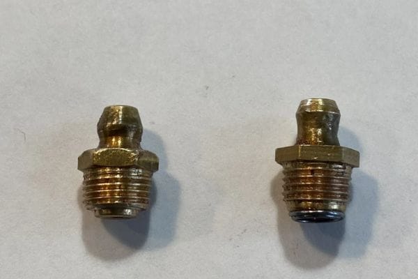
There are several types of metric grease fittings, each suited for specific applications:

Straight Fittings: These are the most common type, featuring a straight-through passage for grease flow.

Angled Fittings: Available in 45-degree and 90-degree angles, these fittings are used where straight fittings cannot be installed due to space constraints.

Flush-Type Fittings: Designed to sit flush with the surface, these fittings are used in applications where protruding fittings could be damaged or interfere with operation.

Drive-Type Fittings: These fittings are installed by driving them into place and are used where threading is not feasible.

Button Head Fittings: These are larger fittings used in heavy machinery where higher volumes of grease are required.

Materials and Uses

Metric grease fittings are manufactured from various materials, each chosen for its specific properties and suitability for different environments:

Steel: The most common material used, steel fittings are durable and cost-effective, suitable for general-purpose applications.

Stainless Steel: Offering superior corrosion resistance, stainless steel fittings are ideal for harsh environments, including marine and chemical processing industries.

Brass: Known for its anti-corrosive properties, brass fittings are often used in applications involving water or mild chemicals.

Zinc-Plated Steel: These fittings provide an additional layer of corrosion resistance and are used in outdoor or moist environments.

Importance of Proper Sizing

Accurate sizing of metric grease fittings is paramount for several reasons:

Effective Lubrication: Properly sized fittings ensure that lubricant reaches all necessary parts of the machinery, reducing friction and wear.

Preventing Leaks: Incorrectly sized fittings can lead to leaks, resulting in insufficient lubrication and potential equipment failure.

Ease of Maintenance: Correctly sized fittings simplify the maintenance process, allowing for quick and efficient lubrication without the need for adapters or modifications.

Safety: Ensuring the right size fittings helps maintain the safety of the equipment, preventing malfunctions that could lead to accidents.

Step-by-Step Measurement Process

Accurately measuring metric grease fittings requires careful preparation and the right tools. This section will guide you through each step of the process to ensure precise measurements.

Preparation

Cleaning the Fitting: Before measuring, thoroughly clean the grease fitting to remove any dirt, grease, or debris. Use a solvent or degreaser and a brush to ensure all residues are removed, as contaminants can affect measurement accuracy.

Inspection: Inspect the fitting for any visible damage or wear. Bent or damaged fittings should not be used for measurement as they can provide inaccurate readings. Replace any defective fittings before proceeding.

Drying: Ensure the fitting is completely dry after cleaning. Moisture can also interfere with accurate measurements.

Measuring the Diameter

External Diameter

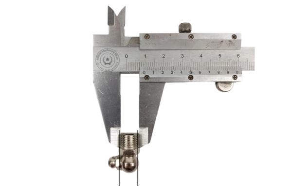
Select the Right Tool: Use a pair of digital or vernier calipers for precise measurement.

Position the Calipers: Open the calipers and place them around the external diameter of the fitting’s threaded part. Ensure the jaws of the calipers are perpendicular to the axis of the fitting to avoid skewed measurements.

Take the Measurement: Gently close the caliper jaws until they touch the fitting’s surface without applying excessive force. Read the measurement displayed on the calipers.

Record the Measurement: Note down the external diameter to the nearest hundredth of a millimeter for accuracy.

Internal Diameter

Select the Tool: For internal diameters, you can use either a pair of small calipers or a micrometer.

Insert the Calipers: Carefully insert the caliper jaws into the internal bore of the fitting. For micrometers, place the spindle inside the bore.

Take the Measurement: Open the calipers or extend the micrometer spindle until they touch the internal walls of the fitting. Ensure the tool is aligned properly to avoid angled measurements.

Record the Measurement: Read and record the internal diameter.

Measure Metric Grease Fitting

Measuring the Thread Pitch

Thread pitch is the distance between threads, measured in millimeters. It is crucial for ensuring compatibility with corresponding components. Accurate thread pitch measurement ensures that the fitting will mate correctly with the receiving part, preventing leaks and mechanical failures.

Using a Thread Gauge

Select the Thread Gauge: Choose a metric thread gauge that includes various pitch sizes.

Match the Threads: Align the teeth of the thread gauge with the threads of the fitting. Start with a pitch size that seems close to the fitting’s thread.

Check the Fit: If the gauge does not fit perfectly, try the next size until you find a match where the gauge teeth align seamlessly with the fitting’s threads.

Record the Pitch: Once you find the correct thread pitch, record the measurement indicated on the gauge.

Measuring the Length

Overall Length

Select the Right Tool: Use a ruler or a set of calipers.

Position the Tool: Align the ruler or calipers with the fitting’s axis to measure from end to end.

Take the Measurement: Measure the entire length of the fitting, including both the threaded and non-threaded parts.

Record the Measurement: Note down the overall length.

Threaded Length

Identify the Threaded Part: Locate the beginning and end of the threaded section of the fitting.

Position the Tool: Place the ruler or calipers at the start of the threads and extend them to the end of the threads.

Take the Measurement: Measure the length of the threaded part.

Record the Measurement: Note the threaded length separately from the overall length.

Common Mistakes and How to Avoid Them

Accurate measurement of metric grease fittings is crucial for ensuring the proper function and longevity of mechanical systems. However, several common mistakes can lead to incorrect measurements, which can cause equipment malfunctions and increased maintenance costs. Understanding these mistakes and how to avoid them is essential for any maintenance professional or engineer.

Incorrect Tool Usage

Common Mistakes:

Using the Wrong Tool: Using a ruler instead of calipers for diameter measurements, or not using a thread gauge for thread pitch, can lead to inaccurate readings.

Improper Calibration: Not calibrating measurement tools before use can result in significant errors.

Inappropriate Pressure: Applying too much or too little pressure with calipers can skew the measurements.

Incorrect Positioning: Misaligning calipers or micrometers can lead to inaccurate diameter and length measurements.

How to Avoid Them:

Choose the Right Tool: Ensure you are using the appropriate tool for each measurement. Use calipers for diameters, micrometers for small internal diameters, and thread gauges for thread pitch.

Calibrate Tools: Regularly calibrate your measurement tools according to the manufacturer’s instructions to ensure accuracy.

Apply Gentle Pressure: When using calipers, apply gentle and consistent pressure to avoid compressing or distorting the fitting.

Align Properly: Ensure that calipers and micrometers are perpendicular to the surface being measured. This alignment helps avoid angular discrepancies.

rust Metric Grease Fitting

Misreading Measurements

Common Mistakes:

Misinterpreting the Scale: Misreading the scale on a vernier caliper or micrometer can lead to incorrect measurements.

Recording Errors: Failing to record measurements immediately or incorrectly noting them down can cause confusion and errors.

Ignoring Decimal Points: Overlooking decimal points in digital readings can result in significant inaccuracies.

Tips on Accurate Reading and Recording:

Understand the Scale: Familiarize yourself with the scales on your measurement tools. For vernier calipers, understand how to read both the main scale and the vernier scale.

Double-Check Readings: Always double-check your readings before recording them. Cross-reference with a colleague if possible.

Use Digital Tools: If available, use digital calipers and micrometers for easier and more accurate readings.

Record Immediately: Write down measurements as soon as they are taken to avoid memory lapses or errors.

Check Decimal Points: Pay close attention to decimal points and ensure they are accurately recorded.

Ignoring Tolerances

Common Mistakes:

Neglecting Manufacturer Specifications: Ignoring the tolerances specified by the manufacturer can lead to poor fitting and mechanical failures.

Assuming Exact Fit: Believing that all fittings are manufactured to exact sizes without considering allowable variances can cause issues.

Importance of Considering Manufacturing Tolerances:

Fit and Function: Manufacturing tolerances account for slight variances in the production process. Understanding these tolerances ensures that parts will fit and function correctly even if there are minor differences in size.

Avoiding Over-tightening: Recognizing that fittings may vary within a specified range helps prevent over-tightening, which can damage parts and lead to leaks.

How to Account for Tolerances:

Refer to Specifications: Always refer to the manufacturer’s specifications for tolerances. These specifications provide an acceptable range of dimensions for each fitting.

Measure Multiple Times: Take multiple measurements to ensure consistency and accuracy. Variations in your readings can help you understand the tolerance range.

Adjust Measurements: If your measurements are close to the tolerance limits, consider the intended application and whether slight adjustments might be needed.

How to Choose the Suitable Metric Grease Fittings

Selecting the appropriate metric grease fittings is crucial for ensuring efficient lubrication and the smooth operation of mechanical systems. The right choice can prevent equipment failure, reduce maintenance costs, and extend the lifespan of machinery. Here’s a comprehensive guide on how to choose the suitable metric grease fittings.

Understand Your Application

Identify the Equipment Type:

Determine the type of machinery or equipment that requires lubrication. Different machines have different lubrication needs and constraints.

Operating Conditions:

Consider the operating environment, including temperature, humidity, and exposure to chemicals or corrosive substances. This will influence the material choice for the grease fittings.

Lubrication Requirements:

Understand the type and viscosity of the lubricant to be used, as this can affect the choice of fitting.

Consider the Size and Thread Type

Measure Existing Fittings:

If replacing existing fittings, measure the old ones to ensure a proper fit. Use calipers and thread gauges for accurate measurements.

Standard Sizes:

Refer to standard metric sizes to ensure compatibility with existing components. Cross-reference your measurements with industry standards.

Thread Type:

Ensure the thread type matches the receiving component. Common thread types include metric fine and coarse threads.

Evaluate Installation and Maintenance Requirements

Ease of Installation:

Choose fittings that are easy to install and do not require special tools or equipment.

Maintenance Accessibility:

Consider how easy it will be to access the fittings for regular maintenance. Angled fittings may be necessary for hard-to-reach areas.

Factor in Load and Pressure Conditions

Load Bearing Capacity:

Ensure the fittings can handle the load and pressure of the equipment. Heavy machinery may require sturdier fittings like button head fittings.

Pressure Rating:

Verify that the fittings can withstand the pressure of the lubrication system. Consult manufacturer specifications for pressure ratings.

Consult Manufacturer Specifications and Recommendations

Manufacturer Guidelines:

Always refer to the machinery or equipment manufacturer’s guidelines for recommended grease fitting types and specifications.

Industry Standards:

Follow industry standards and best practices for selecting grease fittings to ensure safety and compatibility.

Choosing the right metric grease fittings involves understanding your specific application requirements, selecting the appropriate type and material, ensuring the correct size and thread type, considering installation and maintenance needs, and consulting manufacturer guidelines. By following these steps, you can ensure optimal performance, efficiency, and longevity of your mechanical systems.

Conclusion

In conclusion, accurately measuring metric grease fittings is essential for ensuring proper lubrication and the efficient operation of machinery. We covered the types of metric grease fittings, including straight, angled, flush-type, and button head fittings, and the appropriate materials for different applications, such as steel, stainless steel, brass, and zinc-plated steel. Accurate measurements involve using the right tools, avoiding common mistakes, and considering manufacturing tolerances. Precise measurements prevent equipment failures, reduce maintenance costs, and extend machinery lifespan. We encourage you to apply these measurement techniques in your work and share your experiences to help others achieve optimal performance and reliability in their operations.

FAQ

Metric grease fittings, also known as Zerk fittings, are components used to lubricate mechanical systems by allowing grease to be injected into bearing assemblies and other moving parts.

Accurate measurement ensures proper lubrication, prevents leaks, reduces equipment failures, and extends the lifespan of machinery by ensuring the correct fitting size is used.

Common tools include calipers for measuring diameters, thread gauges for measuring thread pitch, and micrometers for precise internal diameter measurements.

Select the material based on the operating environment: steel for general use, stainless steel for corrosive environments, brass for applications involving water or mild chemicals, and zinc-plated steel for additional corrosion resistance.

The common types include straight fittings for direct access points, angled fittings for space-constrained areas, flush-type fittings for surfaces where protruding fittings could be damaged, and button head fittings for high-volume grease requirements in heavy machinery.

Double-check your measurements for accuracy and compare them with industry standards. If discrepancies persist, re-measure and consider manufacturing tolerances or consult with the fitting manufacturer for guidance.

Understanding Metric Pipe Fitting Sizes A Quick Reference

Understanding Metric Pipe Fitting Sizes: A Quick Reference

Understanding Metric Pipe Fitting Sizes: A Quick Reference

Introduction

Metric pipe fitting sizes are a standardized system used globally in various industries, such as plumbing, automotive, and manufacturing, for connecting pipes and tubes. These fittings are essential for ensuring compatibility and efficiency in systems that rely on precise fluid or gas flow. The history of metric pipe fittings dates back to the push for international standardization, which aimed to simplify global trade and manufacturing processes. This guide is designed to help you understand metric pipe fitting sizes, offering a quick and easy reference for accurate and reliable installations.

Basics of Metric Pipe Fitting Sizes

Metric pipe fittings are components used to connect sections of pipe or tubing in systems that require the precise conveyance of fluids or gases. These fittings are measured using the metric system, which is based on meters and millimeters. This standardization allows for consistent and accurate sizing, ensuring that parts from different manufacturers can fit together seamlessly.

Common Materials Used

Metric pipe fittings are manufactured from a variety of materials, each chosen for its specific properties and suitability for different applications. Common materials include:

Brass: Known for its durability and resistance to corrosion, brass is often used in plumbing and heating applications.

Stainless Steel: Valued for its strength and resistance to rust and corrosion, stainless steel fittings are ideal for high-pressure and high-temperature environments.

Plastic: Lightweight and resistant to chemical corrosion, plastic fittings are commonly used in residential plumbing and irrigation systems.

Why Metric?

Using metric fittings offers several advantages compared to imperial fittings. One key advantage is the ease of measurement and calculation. The metric system is based on units of ten, which simplifies conversions and reduces the likelihood of errors during design, manufacturing, and installation. Additionally, metric fittings often provide more precise measurements, which is critical in applications requiring high accuracy.

Global Standardization and Its Benefits

Global standardization through the metric system offers significant benefits, particularly in international trade and manufacturing. With metric fittings, companies can source components from around the world without worrying about compatibility issues, as the sizes are universally recognized. This standardization facilitates smoother supply chains, reduces inventory complexity, and ensures that products meet international quality standards.

Understanding Measurements

How Metric Pipe Fittings Are Measured

Metric pipe fittings are measured using the metric system, typically in millimeters (mm). The key dimensions measured include the outer diameter (OD) and the inner diameter (ID) of the pipe, as well as the thread size if applicable. These measurements are critical for ensuring a proper fit and reliable performance in the assembled system.

Diameter: The diameter of a pipe fitting is one of its most crucial measurements. The outer diameter (OD) is the measurement across the widest point of the fitting, while the inner diameter (ID) is the measurement of the open space inside the fitting. These measurements ensure that the pipe and fitting will fit together properly.

Thread Size: For threaded fittings, the thread size is another essential measurement. This includes the pitch (the distance between threads), the thread angle, and the major diameter (the outer edge of the threads). Accurate thread measurements ensure a secure and leak-free connection.

Other Measurements: Additional measurements that may be important depending on the application include the wall thickness of the pipe (which affects its strength and flow capacity) and the overall length of the fitting. These measurements help in designing systems that are both efficient and durable.

Topa metric hydraulic fitting Manufacturer in China Topa

Types of Metric Pipe Fittings

Straight Fittings

Straight fittings, also known as straight connectors or couplings, are used to connect two sections of pipe or tubing in a straight line. They provide a secure and leak-proof connection, ensuring the continuous flow of fluids or gases without any change in direction. These fittings are commonly used in plumbing, hydraulic, and pneumatic systems, as well as in various industrial applications where a direct, uninterrupted pipeline is required.

Common Sizes and Variations

Straight fittings come in a variety of sizes to match the outer diameter (OD) of the pipes they are connecting. Common sizes include 6 mm, 8 mm, 10 mm, 12 mm, 16 mm, and 20 mm. Variations include different thread types (e.g., BSP, NPT) and configurations, such as male-to-male, female-to-female, and male-to-female connectors.

Elbow Fittings

Elbow fittings are used to change the direction of a pipeline, typically by 90 degrees or 45 degrees. These fittings are essential in systems where the pipes need to navigate around obstacles or fit into confined spaces. Elbow fittings are widely used in plumbing, heating, and cooling systems, as well as in industrial piping networks.

Common Sizes and Variations

Common sizes for elbow fittings include 10 mm, 15 mm, 20 mm, 25 mm, and 32 mm. Variations include different angles (e.g., 45-degree, 90-degree), as well as short-radius and long-radius elbows. Additionally, elbows can be threaded or socket-welded, depending on the application and required connection type.

Tee Fittings

Tee fittings, also known as T-fittings, are used to connect three sections of pipe or tubing, forming a T-shaped intersection. These fittings allow for the branching off of a pipeline into two separate directions, making them ideal for distributing fluids or gases to multiple locations. Tee fittings are commonly found in plumbing, irrigation, and HVAC systems.

Common Sizes and Variations

Standard sizes for tee fittings include 10 mm, 15 mm, 20 mm, 25 mm, and 32 mm. Variations include equal tees (where all three branches are the same size) and reducing tees (where one or more branches are of different sizes). Tees can also have threaded or socket-welded connections.

Reducer Fittings

Reducer fittings are used to connect pipes of different diameters, allowing for a smooth transition between larger and smaller pipes. These fittings are essential in systems where the flow rate or pressure needs to be adjusted by changing the pipe size. Reducers are commonly used in plumbing, HVAC, and industrial piping systems.

Common Sizes and Variations

Common sizes for reducer fittings include combinations such as 20 mm to 15 mm, 25 mm to 20 mm, and 32 mm to 25 mm. Variations include concentric reducers (which have a symmetrical shape) and eccentric reducers (which have an offset shape to prevent air pockets in horizontal pipelines). Reducers can also be threaded or socket-welded.

Coupling Fittings

Coupling fittings, also known as couplers, are short lengths of pipe used to connect two pipes together. They provide a secure and leak-proof connection, making them ideal for extending the length of a pipeline or repairing a damaged section. Couplings are widely used in plumbing, hydraulic, and pneumatic systems.

Common Sizes and Variations

Standard sizes for couplings include 6 mm, 8 mm, 10 mm, 12 mm, 16 mm, and 20 mm. Variations include full couplings (which join two pipes of the same size) and reducing couplings (which join pipes of different sizes). Couplings can also have threaded or socket-welded connections.

Other Specialized Fittings

Specialized fittings are designed for specific applications and may not be as widely used as standard fittings. These include fittings like crosses, unions, caps, plugs, and flanges:

Crosses: Used to connect four sections of pipe in a cross-shaped intersection. Commonly used in fire sprinkler systems and certain industrial applications.

Unions: Allow for easy disconnection and reconnection of pipes, useful in systems that require regular maintenance or assembly.

Caps and Plugs: Used to close off the ends of pipes, preventing the flow of fluids or gases. Essential for system shutdowns or future expansions.

Flanges: Provide a method for connecting pipes, valves, and other equipment with bolts, allowing for easy assembly and disassembly. Commonly used in high-pressure applications.

Selecting the Right Metric Pipe Fitting Size

Pressure Ratings

Definition: Pressure rating indicates the maximum pressure that a fitting can withstand without failing.

Importance: Ensuring that fittings match the pressure requirements of your system is critical for safety and performance.

Selection Tips: Check the specifications provided by the manufacturer. Always select fittings with a pressure rating equal to or higher than the system’s maximum pressure.

Temperature Ratings

Definition: Temperature rating specifies the range of temperatures that a fitting can endure without degrading.

Importance: Using fittings outside their temperature range can lead to failures such as leaks, material degradation, and system inefficiency.

Selection Tips: Consider the operating temperature of your system and select fittings designed to perform well within that range. For extreme temperatures, specialized fittings may be necessary.

Material Compatibility

Definition: Material compatibility ensures that the fitting material is suitable for the type of fluid or gas being conveyed.

Importance: Incompatible materials can cause corrosion, leaks, and system failures.

Selection Tips: Match the fitting material with the fluid or gas type. For example, stainless steel fittings are excellent for corrosive environments, while brass is suitable for water and air applications.

Metric Pipe Fitting Measurement Tips

Use Calipers for Precision

Digital Calipers: Provide highly accurate measurements of both the outer diameter (OD) and inner diameter (ID) of the pipe fittings. Ensure the calipers are zeroed before use.

Vernier Calipers: Also accurate, but require careful reading. Make sure to calibrate them periodically for consistent accuracy.

Thread Gauges for Threaded Fittings

Thread Pitch Gauges: Used to measure the thread pitch (the distance between threads). Select the gauge that fits snugly into the threads without forcing it.

Thread Diameter Gauges: Measure the major and minor diameters of the threads to ensure compatibility with mating parts.

Measuring Tape for Length

Flexible Measuring Tape: Ideal for measuring the overall length of pipes and fittings, especially when dealing with curved or irregular shapes.

hydraulic fittings measure tools Topa

Proper Measurement Points

Outer Diameter (OD): Measure across the widest point of the fitting. Ensure the caliper is perpendicular to the fitting to avoid inaccurate readings.

Inner Diameter (ID): Measure the open space inside the fitting. Ensure the caliper tips touch the inner walls without deforming the fitting.

Thread Size: Measure both the major and minor diameters of the thread. For male threads, measure the outermost points, and for female threads, measure the innermost points.

Practical Tips for Accurate Measurement

Ensure Cleanliness

Clean Fittings: Before measuring, clean the fittings thoroughly to remove any debris, oil, or dirt that could affect the measurement.

Dry Surfaces: Make sure the surfaces are dry to prevent slippage of measuring tools.

Avoid Deformation

Gentle Handling: Handle fittings gently to avoid deforming them during measurement. Deformation can lead to inaccurate readings.

Correct Tool Pressure: Apply consistent, gentle pressure when using calipers to avoid compressing the material.

Measure Multiple Times

Consistency Check: Measure each fitting multiple times to ensure consistency. Record each measurement and take the average to account for any minor discrepancies.

Different Angles: Measure from different angles to confirm uniformity, especially with threaded fittings.

Account for Tolerances

Manufacturer Specifications: Refer to manufacturer specifications for acceptable tolerances. Metric fittings are manufactured within certain tolerance ranges to ensure compatibility.

Fit and Function: Ensure that the measured dimensions fall within these tolerances to guarantee proper fit and function.

Use Appropriate Tools

Calibrated Instruments: Ensure all measuring instruments are calibrated regularly to maintain their accuracy.

Specialized Tools: Use specialized tools like micrometers for high-precision measurements if needed.

Tips for Ensuring a Proper Fit

Match the Sizes

Correct Diameter: Ensure the outer diameter of the pipe matches the inner diameter of the fitting for a snug fit.

Thread Compatibility: Verify that the thread pitch and diameter match between the fitting and the pipe.

Use Sealing Materials

Teflon Tape: Wrap Teflon tape around male threads to ensure a tight seal and prevent leaks.

Pipe Dope: Apply pipe dope (thread sealant) on threads to enhance sealing, especially in high-pressure applications.

Check for Alignment

Proper Alignment: Ensure that the pipes and fittings are properly aligned to avoid stress and potential leaks at the joints.

Support Systems: Use supports and brackets to maintain alignment and prevent sagging or misalignment over time.

Avoid Over-tightening

Tightening Technique: Tighten fittings until they are snug, then apply an additional quarter turn. Over-tightening can strip threads and cause leaks.

Regular Inspection and Maintenance

Routine Checks: Regularly inspect fittings for signs of wear, corrosion, or leaks.

Timely Replacement: Replace any worn or damaged fittings promptly to maintain system integrity.

Conclusion

In summary, understanding metric pipe fitting sizes involves knowing how to measure accurately, considering factors like pressure, temperature, and material compatibility, and using the correct tools and techniques for a secure installation. By following these guidelines, you can ensure efficient and reliable piping systems. For further reading and additional resources, refer to industry standards and guides. If you need expert advice or support, please contact us!

FAQ

What are metric pipe fittings?

Metric pipe fittings are components used to connect pipes or tubes in hydraulic, plumbing, and various other systems, measured using the metric system.

Why should I use metric fittings over imperial fittings?

Metric fittings provide easier and more precise measurements, facilitating global standardization and compatibility across different manufacturers.

How do I measure the size of a metric pipe fitting?

Use calipers to measure the outer diameter (OD) and inner diameter (ID), and thread gauges to determine thread size and pitch.

What materials are common for metric pipe fittings?

Common materials include brass, stainless steel, and plastic, each selected based on their properties and suitability for specific applications.

How do I ensure a proper fit for metric pipe fittings?

Ensure cleanliness, use appropriate sealing materials like Teflon tape, and avoid over-tightening. Align pipes correctly and check for consistency in measurements.

Where can I find more information or support for selecting metric pipe fittings?

Refer to industry standards, and manufacturer’s guides, or contact expert support for personalized advice and further resources.

What Does NPT Mean in Plumbing System?

What Does NPT Mean in Plumbing System

What Does NPT Mean in Plumbing System?

Introduction

It’s crucial to understand the concept of NPT because it’s a common standard used in plumbing systems to ensure a leak-proof seal in your plumbing system. This article will take a comprehensive look at NPT threads, explaining what they are, what they mean in the plumbing industry, and how they are used in various applications.

Understanding NPT

Definition of NPT

NPT, or National Pipe Tapered threads, is a standardized threading system used in plumbing and piping applications to ensure a secure, leak-proof connection. The term “National Pipe Tapered” indicates that the threads are tapered, meaning they gradually decrease in diameter along the length of the thread. This tapering allows for a tighter seal as the threads are screwed together, which is critical for preventing leaks in fluid and gas systems.

NPT fitting guide Topa

Historical Background and Development of NPT Standards

The NPT standard originated in the United States in the late 1800s during the industrial revolution, a time when the need for standardized piping systems became increasingly important due to rapid industrial growth. Before the establishment of NPT, there was a lack of uniformity in pipe threads, which led to frequent leaks and failures in piping systems. Engineers and industry leaders recognized the need for a consistent standard, which led to the development of NPT threads.

Technical Specifications

The tapered design of NPT threads is a key feature that distinguishes them from other types of pipe threads. The taper of NPT threads is designed at an angle of 1°47′ from the center axis. This design causes the diameter of the threads to decrease gradually along the length of the pipe, allowing the threads to form a tighter, more secure fit as they are engaged.

When two NPT-threaded components are screwed together, the taper causes the threads to compress and form a seal. This mechanical seal is enhanced when a thread sealant, such as PTFE tape or pipe dope, is applied to the threads before assembly. The sealant fills any small gaps between the threads, further preventing leaks.

The Role of NPT in Plumbing

Functionality of NPT Threads

NPT threads are specifically designed to create a tight, leak-proof seal through their unique tapered structure. As the threads of a male NPT component are screwed into a female NPT component, the taper causes the threads to compress against each other. This compression increases the surface contact between the threads, which helps to form a mechanical seal. Additionally, the use of thread sealants, such as PTFE tape (commonly known as Teflon tape) or pipe dope, enhances this seal by filling in any small gaps between the threads. The combination of the mechanical fit and the sealant ensures a secure, leak-proof connection that is essential in plumbing applications where fluid or gas leakage must be prevented.

Comparison with Straight Threads

Unlike NPT threads, straight threads (often referred to as parallel threads) maintain a consistent diameter along their entire length. While straight threads can provide a strong mechanical connection, they do not inherently create a seal. For straight threads to be leak-proof, additional sealing mechanisms, such as O-rings or gaskets, are typically required. In contrast, the tapered design of NPT threads eliminates the need for these additional sealing elements, as the taper itself creates the necessary compression to form a seal. This makes NPT threads particularly advantageous in plumbing applications where simplicity and reliability are critical.

Applications in Plumbing

NPT threads are widely used in both residential and commercial plumbing systems due to their reliability and ease of use. In residential settings, NPT threads are commonly found in water supply lines, gas lines, and various plumbing fixtures such as faucets and showerheads. The tapered threads ensure a tight seal, which is crucial for preventing leaks and maintaining the integrity of the plumbing system.

In commercial and industrial settings, NPT threads are used in a broader range of applications, including high-pressure steam systems, chemical processing lines, and large-scale water distribution networks. The ability of NPT threads to withstand high pressure and provide a secure seal makes them ideal for these demanding environments. Additionally, the standardized nature of NPT threads ensures compatibility across various components and systems, simplifying maintenance and repairs.

Examples of NPT threaded Components

Pipes: NPT threads are commonly used on the ends of pipes to allow for secure connections with other pipes or fittings. These threaded pipes are available in various materials, including galvanized steel, stainless steel, brass, and PVC, to suit different applications and environmental conditions.

Fittings: NPT-threaded fittings, such as elbows, tees, and couplings, are essential for directing the flow of fluids and gases within a plumbing system. These fittings are designed to connect pipes at various angles and configurations, making it possible to create complex plumbing networks.

Valves: Valves with NPT threads are used to control the flow of fluids and gases in a plumbing system. Examples include ball valves, gate valves, and check valves. The threaded connections ensure that the valves can be securely installed and easily replaced or serviced when needed.

Pressure Gauges: In many plumbing systems, pressure gauges with NPT threads are used to monitor the pressure of fluids or gases. These gauges provide critical information for maintaining system safety and efficiency, and the threaded connections ensure accurate readings and easy installation.

Pipe Nipples: These short lengths of pipe with NPT threads on both ends are used to connect other threaded components, such as fittings or valves, within a plumbing system. They come in various lengths and materials to match the specific requirements of the application.

NPT Fitting drawing Topa

Types of NPT Thread

Understanding the different types of NPT threads is essential for selecting the right components for various plumbing applications. While all NPT threads share the same basic tapered design, they can be categorized based on their specific features and applications. Here are the main types of NPT threads:

NPTF

Also known as “Dryseal” threads, NPTF threads are designed to provide a leak-proof seal without the need for sealants such as PTFE tape or pipe dope. The threads are manufactured to closer tolerances than standard NPT threads, allowing them to form a dry mechanical seal.

Application: Often used in hydraulic and pneumatic systems where the use of sealants is undesirable or where a more reliable seal is required. NPTF threads are ideal for applications involving fuel and other fluids where leakage cannot be tolerated.

NPS

Unlike NPT threads, NPS threads are straight (parallel) threads and do not taper. They do not create a seal on their own and typically require an O-ring or gasket to form a leak-proof connection.

Application: Used in mechanical joints that do not require a seal through the threads themselves, such as in certain types of conduit or mechanical fittings. NPS threads are often used in conjunction with NPT threads for specific applications where a straight thread is necessary.

NPTF vs NPSM

NPSC

NPSC threads are a subtype of NPS threads specifically designed for coupling applications. These threads are straight and are used to join two pipes or fittings together.

Application: Commonly used in piping systems where straight-threaded couplings are required. They are often used in conjunction with NPT-threaded components to provide a secure connection.

NPTR

NPTR threads are tapered threads similar to standard NPT, but they are specifically designed for use in railing systems. The thread design provides a secure, tight fit for the assembly of railings.

Application: Primarily used in the construction of metal railings, including handrails and guardrails. The tapered threads ensure a strong, stable connection in these structural applications.

NPSM

NPSM threads are straight threads that are typically used in mechanical and low-pressure applications. Like other straight threads, they do not form a seal on their own and usually require a sealing element.

Application: Used in applications where a mechanical connection is needed, but the threads themselves do not need to create a seal. Commonly found in various types of fittings and connectors in hydraulic and pneumatic systems.

NPT vs BSP

Thread Design:

NPT: Features a tapered thread design that provides a tight, leak-proof seal through the compression of threads as they are tightened. The taper angle is 1°47′.

BSP: Includes both parallel (BSPP) and tapered (BSPT) threads. BSPP threads are parallel and require a gasket or O-ring to seal, whereas BSPT threads are tapered and seal similarly to NPT threads.

Angle and Pitch:

NPT: Threads have a 60-degree angle.

BSP: Threads have a 55-degree angle.

Measurement:

NPT: Measured in inches, following the imperial system.

BSP: Measured in inches, but follows the Whitworth standard.

Standards:

NPT: Governed by ANSI/ASME B1.20.1.

BSP: Governed by various British and international standards, including ISO 228-1 (for BSPP) and ISO 7-1 (for BSPT).

Regional preferences and applications:

NPT: Predominantly used in the United States and Canada for plumbing, gas, and hydraulic systems.

BSP: Widely used in the United Kingdom, Europe, Asia, Australia, and other parts of the world. Commonly found in water and gas plumbing applications and hydraulic systems in these regions.

NPT VS BSP Topa

NPT vs Metric Threads

Thread Design:

NPT: Tapered threads that create a seal through thread compression.

Metric Threads: Generally straight (parallel) threads that require an additional sealing mechanism, such as an O-ring or gasket.

Angle and Pitch:

NPT: 60-degree thread angle.

Metric Threads: 60-degree thread angle, but the thread pitch (distance between threads) is measured in millimeters.

Measurement:

NPT: Measured in inches.

Metric Threads: Measured in millimeters, following the metric system.

Applications:

NPT: Common in North American plumbing and piping systems.

Metric Threads: Used internationally, particularly in automotive, machinery, and industrial applications where the metric system is standard.

NPT vs JIC

Thread Design:

NPT: Tapered threads designed to create a seal through thread compression.

JIC: Features a 37-degree flare-fitting design. JIC threads are straight and do not seal through the threads but rather through the metal-to-metal contact of the flared surfaces.

Sealing Mechanism:

NPT: Seals through the compression of tapered threads and often requires a sealant.

JIC: Seals through the flared surfaces of the fittings, creating a strong, reusable connection without the need for additional sealants.

Measurement:

NPT: Measured in inches.

JIC: Also measured in inches, but the fitting dimensions are standardized separately from thread measurements.

Understanding the differences between NPT and other thread standards like BSP, metric threads, and JIC is crucial for selecting the right components for your plumbing and piping systems. Each thread standard has unique features and applications, and choosing the correct type ensures compatibility, reliability, and efficiency in your specific use case.

Installation and Maintenance Tips

Preparing the Threads

Cleaning and Preparing Threads Before Assembly:

Proper preparation of threads is crucial for ensuring a secure and leak-proof connection. Here are the steps to follow:

Inspect the Threads: Before assembly, inspect both the male and female threads for any signs of damage, such as nicks, dents, or deformations. Damaged threads can compromise the seal and lead to leaks.

Clean the Threads: Use a wire brush or thread-cleaning tool to remove any debris, dirt, or old sealant from the threads. Clean threads ensure that the new sealant can adhere properly and that the threads can engage smoothly.

Dry the Threads: Ensure that the threads are dry before applying any sealant. Moisture can interfere with the effectiveness of the sealant and reduce the integrity of the seal.

Using Thread Sealant

PTFE Tape (Teflon Tape):

Application: Wrap the PTFE tape around the male threads in a clockwise direction (as viewed from the end of the pipe). Start from the end of the threads and overlap each wrap slightly. Typically, 2-3 wraps are sufficient for most applications.

Benefits: PTFE tape is easy to use, provides a good seal, and is suitable for a wide range of temperatures and pressures.

Pipe Dope (Thread Sealant Paste):

Application: Apply a thin, even layer of pipe dope to the male threads using a brush or applicator. Be careful not to apply too much, as excess sealant can squeeze out and contaminate the system.

Benefits: Pipe dope provides a strong seal and is often used in high-pressure and high-temperature applications. It remains pliable, making it ideal for applications where vibration or movement is expected.

Anaerobic Thread Sealant:

Application: Apply a small amount of anaerobic thread sealant to the male threads. This type of sealant cures in the absence of air, forming a strong bond.

Benefits: Anaerobic sealants provide excellent resistance to vibration and thermal cycling, making them suitable for industrial and automotive applications.

Proper Tightening Techniques

Avoiding Over-tightening and Ensuring a Proper Fit:

Hand Tightening: Start by hand-tightening the threaded components until they are snug. This ensures that the threads are properly engaged without cross-threading.

Using a Wrench: After hand-tightening, use a wrench to further tighten the connection. Generally, an additional 1-2 turns with a wrench are sufficient. Be cautious not to over-tighten, as excessive force can damage the threads and compromise the seal.

Checking for Proper Fit: After tightening, check that the connection is properly aligned and that the threads are fully engaged. If the connection feels loose or uneven, disassemble and inspect the threads for damage or debris before reassembling.

Conclusion

By mastering the basics of NPT threads and applying best practices for installation and maintenance, you can greatly improve the performance and reliability of your plumbing projects. Proper preparation, correct selection of sealants, and regular maintenance are key success factors. We invite you to share your experiences and insights on using NPT threads in your plumbing projects. Have you encountered specific challenges or found tips that have been beneficial to others? Please feel free to contact us and we will do our best to help you!

FAQ

NPT stands for National Pipe Tapered. It is a standardized threading system used in plumbing to create a tight, leak-proof seal through tapered threads.

NPT threads create a seal through their tapered design. As the threads are tightened, they compress against each other, forming a mechanical seal. Using a thread sealant like PTFE tape or pipe dope enhances the seal by filling any gaps.

Yes, PTFE tape is commonly used on NPT threads to enhance the seal. Wrap the tape clockwise around the male threads 2-3 times before assembling the connection to ensure a leak-proof fit.

NPT threads have a 60-degree angle and a tapered design, while BSP threads have a 55-degree angle and can be either parallel (BSPP) or tapered (BSPT). NPT is primarily used in North America, whereas BSP is widely used in Europe, Asia, and other regions.

NPT threads are tapered, meaning they gradually decrease in diameter. You can measure the threads with a thread gauge or visually inspect the taper. The pitch (distance between threads) is also measured in inches.

If an NPT connection leaks, depressurize the system and re-tighten the connection. Apply additional thread sealant if necessary. Check for any damage to the threads, clean them thoroughly, and ensure proper engagement before reassembling.

NPSM Thread vs NPT Thread What’s the Difference banner

NPSM Thread vs NPT Thread: What’s the Difference?

NPSM Thread vs NPT Thread: What’s the Difference?

Table of Contents

Introduction

Improperly threaded connections can lead to serious system failures, resulting in costly downtime and repairs. Understanding the difference between NPSM and NPT threads can help you select the correct thread type. Choosing the right thread ensures proper sealing, prevents leakage, and optimizes system performance.

Detailed Overview of NPSM Threads

NPSM threads, or National Pipe Straight Mechanical threads, are a type of straight pipe thread that does not taper. Unlike tapered threads, NPSM threads maintain a consistent diameter throughout their length, which allows for a mechanical fit rather than a pressure-tight seal by thread deformation.

Discuss the Key Characteristics

Straight Threads: The primary characteristic of NPSM threads is their straight, parallel threading. This design facilitates a snug fit that relies on an additional sealing method, such as an O-ring or a gasket, to create a leak-proof seal.

Sealing Method: Because NPSM threads are not inherently self-sealing, they typically use O-rings or gaskets to achieve a tight, leak-free connection. This sealing method is beneficial in applications where a reliable, reusable seal is needed.

Thread Design: NPSM threads are designed to match the same thread pitch and diameter as NPT threads, but they do not provide a seal through the threads themselves. Instead, the mechanical strength of the connection is supplemented by the external sealing mechanism.

Applications of NPSM Threads

NPSM threads are widely used in various industries due to their reliable sealing capabilities and ease of maintenance. Common applications include:

Hydraulic Systems: NPSM threads are frequently used in hydraulic systems where precise and reliable connections are crucial for maintaining system pressure and preventing leaks.

Pneumatic Systems: These threads are also popular in pneumatic systems where air-tight seals are necessary to ensure efficient operation.

Automotive Industry: In automotive applications, NPSM threads are used in fuel lines, brake systems, and other critical components that require reliable, leak-free connections.

Examples of Equipment and Systems Utilizing NPSM Threads:

Hydraulic Pumps and Cylinders: NPSM threads are commonly found in hydraulic pumps and cylinders, ensuring secure connections that withstand high pressures.

Pneumatic Tools and Equipment: In pneumatic systems, NPSM threads provide dependable connections for air hoses and tools.

Industrial Machinery: Many types of industrial machinery rely on NPSM threads for various fluid and air connections, ensuring optimal performance and safety.

Advantages of NPSM Threads

Easy Assembly: NPSM threads are straightforward to assemble, requiring only basic tools and minimal effort. This ease of assembly reduces installation time and labor costs.

Reliable Sealing: When used with appropriate O-rings or gaskets, NPSM threads provide highly reliable, leak-free connections. This is particularly beneficial in systems where frequent disassembly and reassembly are required.

Reusability: The use of external seals means that NPSM threaded connections can be disassembled and reassembled multiple times without compromising the integrity of the seal.

Versatility: NPSM threads are compatible with a wide range of sealing materials and can be used in various applications, from high-pressure hydraulic systems to low-pressure pneumatic systems.

Limitations of NPSM Threads

Need for External Seals: One of the primary limitations of NPSM threads is their reliance on external sealing mechanisms. Without an O-ring or gasket, NPSM threads cannot form a leak-proof connection, which can be a disadvantage in some applications.

Not Suitable for All Environments: The effectiveness of the seal in NPSM threads depends on the material and condition of the O-ring or gasket. In environments with extreme temperatures or aggressive chemicals, these sealing materials may degrade, leading to potential leaks.

Maintenance Requirements: Regular inspection and maintenance of the sealing elements (O-rings or gaskets) are necessary to ensure ongoing leak-free performance. This can increase the overall maintenance burden compared to self-sealing thread types like NPT.

Pressure Limitations: While NPSM threads are suitable for many high-pressure applications, they may not be the best choice for the highest-pressure systems where the integrity of the seal is paramount.

Define NPT Threads

NPT threads, or National Pipe Tapered threads, are a type of pipe thread used widely in North America. They have a taper of 1° 47′ 24″ (1.7899°) resulting in a 1/16 taper over one inch of length. This tapering design helps create a tight seal through the interference fit between the male and female threads.

Discuss the Key Characteristics

Tapered Threads: The key characteristic of NPT threads is their taper. As the threads advance, they become tighter, creating a seal through the deformation of the threads.

Sealing Method: The primary sealing method for NPT threads involves the interference fit and deformation of the threads. This often requires the use of a thread sealant, such as Teflon tape or pipe dope, to ensure a leak-proof connection.

Thread Design: NPT threads are designed to tighten as they are screwed together, with the tapered nature of the threads increasing friction and creating a seal that holds pressure effectively.

NPT Fitting drawing Topa

Applications of NPT Threads

NPT threads are used extensively across a variety of industries due to their robust sealing capabilities. Common applications include:

Oil and Gas Industry: NPT threads are widely used in pipelines, drilling equipment, and other high-pressure applications in the oil and gas sector.

Water Supply Systems: They are frequently employed in plumbing and water supply systems for their reliable sealing properties.

HVAC Systems: NPT threads are utilized in heating, ventilation, and air conditioning systems to ensure secure connections in various components.

Examples of Equipment and Systems Utilizing NPT Threads:

Piping Systems: NPT threads are commonly used in piping systems for both liquid and gas transport.

Pressure Vessels: In pressure vessels and tanks, NPT threads provide secure connections for gauges, valves, and other fittings.

Hydraulic Equipment: NPT threads are also used in hydraulic equipment where reliable sealing under high pressure is critical.

Advantages of NPT Threads

Strong Sealing: The tapered design of NPT threads creates a strong, pressure-tight seal through the deformation of the threads, which is effective for high-pressure applications.

Widespread Use: NPT threads are standardized and widely recognized, making them easily available and understood by professionals across various industries.

No Need for External Seals: Unlike NPSM threads, NPT threads do not necessarily require O-rings or gaskets, relying instead on thread deformation and sealant for leak-proof connections.

Cost-Effective: The simplicity of NPT threads often makes them a cost-effective solution for many applications, reducing the need for additional sealing components.

Limitations of NPT Threads

Thread Deformation: The primary sealing method for NPT threads involves thread deformation, which can make the fittings difficult to disassemble and reassemble. Over time, repeated assembly and disassembly can wear down the threads, leading to potential leaks.

Installation Challenges: Proper installation of NPT threads requires experience and skill to ensure a tight seal without over-tightening, which can damage the threads. The use of sealants like Teflon tape must be done correctly to prevent leaks.

Compatibility Issues: NPT threads are not compatible with other types of threads, such as NPSM, without the use of adapters. This can limit their use in systems where different thread types are required.

Sealant Dependency: While NPT threads do not require external seals, they often depend on thread sealants to achieve a leak-proof connection. Incorrect application of sealants can compromise the integrity of the seal.

Other Threads Related to NPT

NPTF (National Pipe Tapered Fuel) Threads

NPTF Threads: Also known as Dryseal threads, NPTF threads are designed to create a pressure-tight seal without the use of sealants.

Key Characteristics: NPTF threads have the same taper as NPT threads but are manufactured to stricter tolerances. The threads deform slightly to create a seal when tightened, eliminating the need for additional sealing materials.

Applications of NPTF Threads:

  • Fuel Systems: Commonly used in fuel systems where leak prevention is critical.
  • Hydraulic and Pneumatic Systems: Used in high-pressure hydraulic and pneumatic applications.
  • Industrial Equipment: Utilized in industrial machinery requiring reliable, leak-free connections without sealants.

NPS (National Pipe Straight) Threads

NPS Threads: NPS, or National Pipe Straight threads, are straight threads that do not taper. They are designed for mechanical joining rather than for sealing fluids.

Key Characteristics: NPS threads maintain a constant diameter throughout their length. They rely on a gasket or O-ring for sealing rather than the threads themselves.

Applications of NPS Threads:

  • Fire Protection Systems: Used in fire hydrants and sprinkler systems where a mechanical fit is sufficient, and sealing is provided by gaskets.
  • Plumbing Fixtures: Common in plumbing applications where fittings need to be easily assembled and disassembled.
  • Industrial Equipment: Utilized in various industrial applications where reliable mechanical connections are needed.

Practical Considerations

NPTF vs NPSM

Application Requirements

Pressure Levels: Consider the pressure levels of the application. NPT threads are often preferred for high-pressure applications due to their tapered design that creates a strong, pressure-tight seal.

Sealing Needs: If the application requires a robust, leak-free connection without additional sealants, NPT threads might be more suitable. Conversely, if the system can accommodate an external sealing method like an O-ring or gasket, NPSM threads can be a good choice.

Mechanical Connections: For applications where frequent disassembly and reassembly are required, NPSM threads are preferable due to their straight design and ease of reuse.

Environmental Conditions

Temperature and Chemical Exposure: Evaluate the operating environment, including temperature fluctuations and exposure to chemicals. NPT threads may provide better sealing in harsh environments, whereas NPSM threads with appropriate seals can offer flexibility.

Corrosion Resistance: Consider the material of the fittings and the potential for corrosion. Both NPT and NPSM threads are available in various materials, so choose one that offers the best resistance to environmental conditions.

Ease of Installation and Maintenance

Assembly Complexity: If ease of installation is a priority, NPSM threads might be preferred due to their straight threading, which simplifies alignment and assembly.

Maintenance Requirements: Consider the long-term maintenance needs. NPSM threads, with their external seals, might require regular inspection and replacement of O-rings or gaskets, whereas NPT threads may have less frequent maintenance needs if properly installed.

Installation Tips

NPSM Threads:

Use of Seals: Ensure that appropriate O-rings or gaskets are used to achieve a leak-free connection. Verify that the seals are compatible with the fluid and the operating conditions.

Proper Alignment: Align the threads carefully to avoid cross-threading, which can damage the threads and compromise the seal.

Tightening: Do not overtighten NPSM connections. Tighten until the O-ring or gasket makes contact and forms a seal, then apply a final torque to ensure the connection is secure.

NPT Threads:

Thread Sealant: Apply a suitable thread sealant, such as Teflon tape or pipe dope, to the male threads. Ensure even coverage without excess sealant that could contaminate the system.

Correct Tightening: Tighten the connection until hand-tight, then use a wrench to apply additional turns as recommended (usually 2-3 turns). Avoid over-tightening to prevent thread deformation.

Inspection: After assembly, inspect for any signs of leakage and make adjustments as needed. Ensure that the sealant is properly applied and the threads are not damaged.

Discuss Common Pitfalls and How to Avoid Them:

  • Cross-Threading: To avoid cross-threading, always start threading connections by hand and ensure proper alignment before using tools.
  • Over-Tightening: Over-tightening can lead to thread deformation and potential leaks. Follow manufacturer recommendations for torque specifications.
  • Inadequate Sealing: Ensure that the correct type and amount of sealant is used. Inadequate sealing can result in leaks, while excess sealant can cause blockages.

Conclusion

NPSM and NPT threads serve different purposes. NPSM threads provide easy assembly and reliable sealing through external seals, while NPT threads provide a strong pressure-tight connection through thread deformation. Choosing the correct thread type is critical to ensuring system reliability, safety and performance. For further reading and detailed specifications, please browse our other articles on the subject, or contact Topa directly.

FAQ

NPSM threads are straight threads used primarily for mechanical connections, often requiring O-rings or gaskets to achieve a leak-proof seal.

NPT threads are tapered threads that create a tight seal through thread deformation, commonly used in high-pressure applications.

Use NPSM threads when you need easy assembly and disassembly, especially in applications that require external sealing elements like O-rings or gaskets.

NPT threads are ideal for applications requiring strong, pressure-tight seals without additional sealing materials, such as in high-pressure piping systems.

Generally, NPSM and NPT threads are not compatible without adapters, as NPSM threads are straight and NPT threads are tapered.

NPT threads offer strong sealing through thread deformation, are widely recognized and standardized, and often do not require external seals for leak-proof connections.

SAE vs Metric Grease Fittings A Detailed Guide

SAE vs Metric Grease Fittings: A Detailed Guide

SAE vs Metric Grease Fittings: A Detailed Guide

Introduction

Grease fittings are small components that play an important role in machinery maintenance by allowing easy and efficient application of lubricant to moving parts. Proper lubrication is critical to minimizing wear, preventing corrosion, and extending equipment life. This detailed guide is designed to give readers a comprehensive understanding of SAE and metric grease fittings, including their features, applications, compatibility and selection criteria, so they can make informed decisions about their maintenance practices.

Understanding Grease Fittings

Grease fittings, also known as grease nipples or zerks, are mechanical components designed to facilitate the application of lubricants to moving parts of machinery. These fittings serve as access points through which grease can be injected directly into bearings, joints, and other components, ensuring that they remain well-lubricated and function smoothly. The primary function of grease fittings is to provide a sealed and secure pathway for lubricant delivery, preventing contaminants from entering the system and ensuring that lubrication reaches the intended areas effectively.

There are several types of grease fittings, each suited to different applications and environments. The most common types include:

Standard Grease Fittings: These are the most widely used and come in various thread sizes to fit different machinery. They feature a ball check mechanism that prevents dirt and debris from entering the fitting.

Flush Grease Fittings: These are designed to be flush with the surface of the machinery, making them less prone to damage in environments where protruding fittings might be knocked off or damaged.

Button Head Grease Fittings: Characterized by their larger diameter heads, these fittings are used in heavy-duty applications where a large volume of grease is required. They are particularly useful in industrial and construction equipment.

Proper lubrication is paramount in machinery maintenance, as it significantly reduces friction and wear between moving parts. Without adequate lubrication, components can quickly degrade, leading to increased downtime, higher maintenance costs, and a shorter lifespan for the machinery. Grease fittings ensure that the lubricant is delivered precisely where it is needed, enhancing the performance and reliability of the equipment. Additionally, regular lubrication through grease fittings helps in preventing rust and corrosion, which can compromise the integrity of the machinery over time.

Overview of SAE Grease Fittings

SAE grease fittings are predominantly used in the automotive industry, given their origins. However, their use has expanded to various other sectors, including agriculture, construction, aerospace, and heavy machinery. These fittings are integral to the maintenance of equipment such as tractors, excavators, aircraft, and industrial machines. The standardized nature of SAE fittings makes them highly versatile, suitable for a wide range of applications where reliable lubrication is critical.

Characteristics and Specifications of SAE Grease Fittings

SAE grease fittings are known for their precise engineering and durability. Key characteristics and specifications include:

Thread Sizes: SAE grease fittings come in a variety of thread sizes to accommodate different equipment requirements. Common thread sizes include 1/4″-28, 1/8″-27, 5/16″-18, and 3/8″-24, among others. These sizes correspond to specific applications and ensure a secure fit within the designated lubrication points.

Pressure Ratings: SAE grease fittings are designed to withstand varying pressure levels, ensuring that they can handle the demands of different lubrication systems. Typical pressure ratings for these fittings range from 6,000 to 10,000 psi, depending on the specific type and application. This ensures that the fittings can deliver lubricant effectively without leaking or failing under high pressure.

Materials Used: SAE grease fittings are typically made from durable materials such as steel, stainless steel, and brass. Steel fittings are commonly used due to their strength and cost-effectiveness. Stainless steel fittings offer superior corrosion resistance, making them suitable for harsh environments.

Overview of Metric Grease Fittings

Metric grease fittings are widely used in industries and regions that have adopted the metric system, including Europe, Asia, and many parts of Africa and Latin America. Common applications include automotive manufacturing, heavy machinery, industrial equipment, and agricultural machinery. Metric fittings are essential in maintaining equipment such as cars, trucks, construction vehicles, and farm equipment. Their use in these industries ensures that machinery remains well-lubricated and operates efficiently, reducing downtime and maintenance costs.

Characteristics and Specifications of Metric Grease Fittings

Metric grease fittings are designed to meet specific engineering standards, ensuring they provide reliable and efficient lubrication. Key characteristics and specifications include:

Thread Sizes: Metric grease fittings come in a range of thread sizes to suit different machinery and applications. Common thread sizes include M6x1, M8x1, M10x1, and M12x1. These sizes denote the diameter and pitch of the threads, allowing for precise fitting and secure attachment within lubrication points.

Pressure Ratings: Metric grease fittings are built to withstand high-pressure environments, ensuring they can deliver lubricant effectively without leakage or failure. Typical pressure ratings for these fittings range from 6,000 to 10,000 psi, similar to SAE fittings. This ensures they can handle the demands of various lubrication systems and maintain consistent performance under pressure.

Materials Used: The materials used in the construction of metric grease fittings are chosen for their durability and resistance to wear and corrosion. Common materials include steel, stainless steel, and brass. Steel fittings are favored for their strength and affordability, making them suitable for general applications. Stainless steel fittings offer excellent corrosion resistance and are ideal for use in harsh or corrosive environments. Brass fittings are also used for their corrosion resistance and ease of machining, often found in specialized applications where precision is critical.

Key Differences Between SAE and Metric Grease Fittings

Measure Metric Grease Fitting drawing

Thread Types and Sizes Comparison

One of the most notable differences between SAE and Metric grease fittings lies in their thread types and sizes. SAE (Society of Automotive Engineers) grease fittings typically use imperial thread sizes, such as 1/4″-28, 1/8″-27, 5/16″-18, and 3/8″-24. These threads are specified in inches and follow the Unified Thread Standard (UTS).

On the other hand, Metric grease fittings use thread sizes measured in millimeters, such as M6x1, M8x1, M10x1, and M12x1. The “M” denotes that the threads are metric, and the numbers indicate the diameter and pitch of the threads. The pitch refers to the distance between threads, which is crucial for ensuring a proper fit.

This difference in thread types means that SAE and Metric grease fittings are not directly interchangeable. Using the wrong type of thread can result in poor fitment, potential leakage, and damage to the machinery.

Dimensional Differences and Tolerances

SAE and Metric grease fittings also differ in their dimensional standards and tolerances. SAE fittings follow the UTS dimensional standards, which have specific guidelines for thread depth, diameter, and pitch. These standards ensure consistency and compatibility among various SAE fittings.

Metric grease fittings adhere to the International Organization for Standardization (ISO) standards, which dictate the dimensions and tolerances for metric threads. ISO standards ensure that Metric fittings maintain consistent thread dimensions and pitches, facilitating their use in metric-based systems.

Dimensional differences and tolerances between SAE and Metric fittings can affect the ease of installation and the reliability of the seal. Properly adhering to these standards is essential to ensure that the fittings perform optimally and do not cause mechanical issues.

Pressure Ratings and Performance Differences

While both SAE and Metric grease fittings are designed to handle high pressures, there can be differences in their performance based on their construction and application. Typical pressure ratings for both types of fittings range from 6,000 to 10,000 psi. However, specific applications might require fittings that can handle higher or lower pressures.

SAE fittings are often used in applications with rigorous performance requirements, such as automotive and aerospace industries. Their pressure ratings and performance are standardized to meet the stringent demands of these sectors.

Metric fittings, while also capable of handling high pressures, are commonly used in industrial and machinery applications. Their performance standards are set to meet the needs of these environments, ensuring reliable lubrication under various conditions.

Selection Criteria

Choosing the right grease fittings for your machinery is crucial for ensuring efficient lubrication and long-term reliability. When selecting between SAE and Metric grease fittings, several factors should be considered to ensure compatibility, performance, and ease of maintenance.

BSP grease fittings wholesale

Performance Requirements

Load and Pressure: Assess the operational load and pressure requirements of your machinery. High-load and high-pressure applications may require fittings with specific pressure ratings. Ensure that the selected grease fittings can handle the maximum pressure without risk of leakage or failure.

Lubricant Delivery: Consider the type and viscosity of the lubricant used. Some fittings are designed to accommodate thicker greases, while others are optimized for lighter oils. The fitting should ensure consistent and effective lubricant delivery to the critical parts of the machinery.

Frequency of Lubrication: Determine how often the machinery requires lubrication. Frequent lubrication needs might necessitate fittings that are easy to access and use, while less frequent needs might allow for more secure, less accessible fittings.

Environmental Factors

Operating Environment: Evaluate the conditions in which the machinery operates. In harsh environments with exposure to dirt, dust, moisture, or chemicals, corrosion-resistant materials like stainless steel or brass may be necessary to ensure longevity and reliability.

Temperature Extremes: Consider the temperature range within which the machinery operates. Extreme temperatures can affect the performance and durability of grease fittings. Materials and designs that can withstand high or low temperatures without degradation are preferable.

Exposure to Contaminants: Machinery exposed to contaminants requires grease fittings with effective sealing mechanisms to prevent dirt and debris from entering the lubrication system. This ensures the lubricant remains clean and effective.

Maintenance Considerations

Ease of Installation and Removal: Choose grease fittings that are easy to install and remove. This is particularly important for machinery that requires frequent maintenance. Quick and straightforward installation helps reduce downtime and maintenance costs.

Compatibility with Existing Equipment: Ensure that the new grease fittings are compatible with the existing equipment. This includes matching thread sizes, types, and material compatibility. Using fittings that align with current standards and specifications prevents potential issues during maintenance.

Availability and Replacement: Consider the availability of the grease fittings in your region. Easily accessible fittings reduce downtime when replacements are needed. Standardized fittings (either SAE or Metric) that are widely available can be advantageous.

Durability and Longevity: Select fittings made from high-quality materials that offer durability and long service life. This minimizes the need for frequent replacements and ensures continuous, reliable lubrication.

Selecting the right grease fittings involves a comprehensive evaluation of performance requirements, environmental factors, and maintenance considerations. By understanding the specific needs of your machinery and the conditions it operates in, you can choose grease fittings that enhance lubrication efficiency, reduce maintenance efforts, and extend the lifespan of your equipment. Whether opting for SAE or Metric fittings, ensuring compatibility and reliability is key to achieving optimal machinery performance and operational efficiency.

Installation and Maintenance Tips

Preparation: Before installation, ensure that the fitting and the receiving hole are clean and free from debris or old grease. Use a clean cloth or brush to remove any contaminants.

Thread Sealing: Apply a suitable thread sealant or Teflon tape to the threads of the grease fitting to prevent leaks and ensure a secure fit. This is especially important in high-pressure applications.

Insertion: Carefully screw the grease fitting into the receiving hole by hand to avoid cross-threading. Once it is hand-tight, use a wrench or a special grease fitting installation tool to secure it firmly in place. Avoid over-tightening, which can damage the threads and the fitting.

Alignment: Ensure the grease fitting is aligned correctly to allow easy access for the grease gun. Misalignment can make future lubrication difficult and may cause damage during maintenance.

Common Installation Mistakes and How to Avoid Them

Cross-Threading: One of the most common mistakes is cross-threading the fitting during installation. To avoid this, always start threading the fitting by hand and ensure it is properly aligned before using a wrench.

Over-Tightening: Over-tightening can strip the threads or damage the fitting. Tighten the fitting until it is snug and then apply a slight additional turn for security. Do not force it beyond this point.

Inadequate Sealing: Failing to use a thread sealant can lead to leaks. Always apply a suitable sealant to the threads before installation.

Troubleshooting Common Problems

Grease Leakage: If grease is leaking around the fitting, check for proper installation and ensure that the threads are sealed correctly. Replace damaged or worn fittings.

Blocked Fittings: If no grease is coming out when you apply the grease gun, the fitting may be blocked. Remove the fitting and clean it or replace it if necessary. Check the passage in the machinery for blockages as well.

Fitting Damage: If the fitting is damaged, bent, or worn, replace it immediately. Operating with a damaged fitting can lead to insufficient lubrication and potential machinery failure.

Difficulty in Lubrication: If it is hard to attach the grease gun or apply grease, ensure that the fitting is the correct type and size for your equipment. Also, check that the grease gun is functioning properly and filled with the correct lubricant.

Conclusion

In this detailed guide, we have explored the differences between SAE and metric grease fittings. By thoroughly evaluating these needs and understanding the unique benefits of each standard, you can make an informed decision that ensures optimal lubrication, performance, and service life for your equipment.

FAQ

SAE grease fittings use imperial thread sizes and are commonly used in the US, while Metric grease fittings use metric thread sizes and are prevalent in Europe and Asia.

No, SAE and Metric grease fittings are not interchangeable due to differences in thread types and sizes.

Common materials for grease fittings include steel, stainless steel, and brass, chosen for their durability and corrosion resistance.

To prevent cross-threading, always start threading the fitting by hand, ensuring it is properly aligned before using a wrench to secure it.

Thread sealant prevents leaks and ensures a secure fit, especially important in high-pressure applications.

Regularly inspect grease fittings for wear, damage, and blockages. Follow the manufacturer’s recommended lubrication schedule and keep fittings clean to ensure optimal performance.

SAE Thread Fitting Types What You Need to Know

SAE Thread Fitting Types: What You Need to Know

SAE Thread Fitting Types: What You Need to Know

Table of Contents

Introduction

SAE fittings play a pivotal role in a myriad of industrial applications, beyond just automobiles and heavy machinery. These fittings are standardized under SAE guidelines, which ensures that they meet rigorous quality and safety standards crucial for applications in aerospace, agriculture, and construction equipment. This standardization helps manufacturers and maintenance teams streamline compatibility and inventory management, greatly reducing the risk of mismatches and equipment downtime.

Understanding SAE Threads

Basics of Thread Fitting

In mechanical engineering, threads are vital for assembling and disassembling components without causing damage or requiring permanent alterations. These helical structures facilitate the conversion of rotational movement into linear force, a principle central to many mechanical systems such as screws, bolts, and hydraulic fittings. Threads enable a tight fit between parts, which is crucial for maintaining pressure and preventing leaks in systems subjected to high dynamic loads. Their design allows for easy maintenance and repair by enabling components to be connected securely and removed as needed, which is particularly valuable in industrial applications where regular adjustments and inspections are necessary.

Introduction to SAE Fittings

SAE threads, established by the Society of Automotive Engineers, are designed to meet the stringent requirements of hydraulic systems, which demand robust sealing capabilities and enduring strength. These threads are characterized by their distinctive profile shapes that maximize sealing efficiency and mechanical fit. They are available in a variety of inch-based sizes and thread-per-inch configurations, providing a wide range of options to achieve the best fit for any given application. This standardization of thread profiles ensures that components are interchangeable and meet universal performance expectations, facilitating their use across a broad spectrum of industries and applications. The design and rigorous testing standards associated with SAE threads ensure they can withstand the pressures and challenges typical of modern hydraulic systems, thus guaranteeing reliability and safety in operation.

Types of SAE Fittings

SAE (Society of Automotive Engineers) hydraulic fittings are essential components in various hydraulic systems, designed to ensure tight and leak-free connections. Here’s a list of some common types of SAE hydraulic fittings, each serving specific applications and operational requirements:

SAE J514 37-Degree Flare (JIC) Fittings

The SAE J514 37-degree flare fittings, commonly referred to as JIC fittings, are renowned for their robust design which includes a flared tube end that provides a strong, durable metal-to-metal seal. This type of fitting is exceptionally versatile, and suitable for use in agricultural equipment, construction machinery, and aerospace applications. Their ability to handle medium to high-pressure conditions makes them ideal for hydraulic fluid conveyance in environments where shock and vibration are prevalent.

SAE O-Ring Boss Fittings

SAE ORB adapters supplier in China

SAE ORB fittings are designed with a male thread and an O-ring seated in a groove on the male face, offering a superior seal through the O-ring. This setup is particularly effective in high-pressure applications, ranging from hydraulic lifts to industrial presses, where the prevention of leaks is paramount. The simplicity of the seal structure allows for easier assembly and maintenance, enhancing their popularity in both static and dynamic hydraulic systems.

SAE O-Ring Face Seal Fittings

The ORFS fittings provide excellent leak protection with a zero-clearance design. The flat face and O-ring groove ensure a tight seal, reducing the potential for leaks, which is critical in systems exposed to high vibrations, such as mobile hydraulics and marine steering systems. The ORFS fittings’ robust design makes them suitable for high-pressure applications where hydraulic shock and fluctuations are common, ensuring a reliable and maintenance-free operation.

SAE Flange Fittings

SAE Flange fittings come in two main types: split (which includes two separate pieces that enclose the flange) and monoblock (where the flange is integrated as a single piece). These fittings are used extensively in heavy-duty applications, such as in commercial vehicles, large construction equipment, and industrial machinery, where large-diameter pipes or high-pressure flows are common. Their high strength and durability provide a secure and stable connection capable of withstanding extreme pressure and mechanical stress.

SAE 45-Degree Flare Fittings

This type of fitting, featuring a 45-degree flare angle, is generally used in lower-pressure environments compared to its 37-degree counterpart. Its applications include fuel and oil lines in automotive and aerospace industries, where a tight seal is necessary but the system pressure is relatively lower. The 45-degree flare fitting is particularly favored for its ease of assembly and effectiveness in systems where space and accessibility are limited.

SAE Inverted Flare Fittings

inverted flare Field attachable fitting Topa

Typically found in automotive applications, especially in brake and fuel systems, SAE inverted flare fittings are designed to provide reliable, leak-free connections in systems that require a metal-to-metal seal. The tube is flared outward and the fitting’s body provides the mating surface to form the seal. This design is highly effective for handling the high pressures seen in brake lines, ensuring safety and reliability in critical vehicle systems.

Each of these SAE hydraulic fitting types is crafted to meet specific technical standards and to perform reliably under varying conditions, making them indispensable in the realm of hydraulic systems design and maintenance.

Specifications and Standards

Technical Specifications

The technical specifications of SAE straight thread fittings are designed to meet rigorous industry requirements, ensuring performance under high pressure and adverse conditions. For instance, a common specification such as the 1/2-20 UNF thread size, featuring 20 threads per inch, is meticulously designed to ensure robust engagement and sealing capabilities. These specifications not only indicate the diameter and pitch of the thread but also define the type of seal required and the pressure rating. For hydraulic systems, these dimensions are critical as they must match precisely to prevent leaks and ensure system integrity. Materials used in these fittings are typically high-strength steel or stainless steel, chosen for their durability and resistance to corrosion and wear.

Standard Compliance and Certification

Adherence to established standards like SAE J514, which covers hydraulic tube fittings, is crucial for maintaining safety and efficiency across the industry. These standards are comprehensive, detailing not only the physical dimensions and tolerances but also the material specifications and assembly requirements. Compliance with such standards ensures that fittings from different manufacturers are interchangeable and can operate reliably in a unified system. Certification processes involve rigorous testing for durability, pressure resistance, and environmental resilience, guaranteeing that the fittings perform well under specified conditions.

Importance of Standardization in Hydraulic Systems

Standardization in hydraulic fittings, as enforced by standards like SAE J514, facilitates several critical benefits:

Interoperability: Ensures that components from different manufacturers can be used together without compatibility issues.

Safety: Reduces the risk of failures and leaks, which can lead to operational hazards and environmental damage.

Quality Assurance: Provides a benchmark for quality, helping consumers select products that meet industry-recognized criteria.

Innovation: Encourages manufacturers to innovate within the parameters of the standards, leading to improvements in efficiency and performance.

Industry Adoption and Regulatory Impact

The widespread adoption of SAE standards in the hydraulic fittings industry not only simplifies the design and maintenance of hydraulic systems but also influences regulatory practices. Regulatory bodies often incorporate these standards into safety and environmental regulations, which helps to streamline compliance efforts for manufacturers and users alike. The alignment of industry standards with regulatory requirements ensures that hydraulic systems are not only efficient and interchangeable but also compliant with international safety and environmental standards.

By adhering to precise technical specifications and robust standard compliance, the hydraulic fittings industry can maintain high levels of safety, reliability, and performance, ultimately contributing to the overall efficiency and sustainability of hydraulic systems across various applications.

Choosing the Right SAE Thread Fitting

Selecting the appropriate SAE hydraulic fitting is a meticulous process that demands consideration of several critical factors. These factors are designed to ensure optimal performance and longevity in hydraulic systems, where the right fitting can mean the difference between efficient operation and costly downtime.

Material Compatibility

material Topa China factory

Key Consideration: The compatibility of the fitting material with the hydraulic fluid is vital to prevent adverse chemical reactions that can degrade the material of the fitting, leading to leaks and potential system failure.

Common Materials:

Stainless Steel: Offers excellent corrosion resistance and strength, making it suitable for a wide range of hydraulic fluids and environments.

Carbon Steel: Generally less expensive than stainless steel and effective in non-corrosive environments. It’s commonly used where little to no moisture is present.

Brass: Best suited for applications involving water-based fluids and gases, brass fittings are resistant to corrosion from water but may not be suitable for stronger acids or alkalis.

Pressure Ratings

Importance: Ensuring the fitting can handle the system’s maximum pressure is critical to prevent blowouts and failures. The fitting must sustain not just the average working pressure but also any spikes or surges.

Assessment:

Verify Ratings: Check the pressure ratings of the fittings, often measured in psi (pounds per square inch). Ensure that the fitting’s rating exceeds the maximum expected system pressure by a safe margin.

Factor in Safety Margins: Engineering standards often recommend a safety factor, usually about 1.5 to 4 times the maximum operating pressure, depending on the application’s criticality and variability.

Environmental Factors

Temperature:

Range Consideration: The temperature range within which the system operates must be within the tolerable range of the fitting material. Extreme temperatures can affect the resilience and sealing capability of the material.

Thermal Expansion: Materials expand and contract with temperature changes. This dimensional change can affect the tightness and efficacy of the seal.

Corrosion Potential:

Environmental Exposure: Fittings exposed to corrosive environments, such as marine settings or areas with chemical exposure, require materials like high-grade stainless steel or specially coated metals.

Protective Measures: In highly corrosive environments, consider additional protective measures such as coatings, anodic protection, or using more inert materials to prolong the life of the fittings.

When choosing SAE fittings, it’s not just about selecting the right type but also about ensuring that every aspect of the fitting is tailored to the operational demands and environmental conditions of the system. Detailed knowledge of material properties, pressure requirements, and environmental factors is crucial for making informed decisions.

Troubleshooting Common Issues

Maintaining the integrity and performance of SAE thread fittings is vital to ensure the long-term reliability of hydraulic systems. Below are expanded insights into common issues and their comprehensive troubleshooting methods:

Incorrect Thread Engagement

Problem Description: Incorrect thread engagement often leads to several issues like leaks, which can compromise the hydraulic system’s efficiency, or thread stripping, which severely undermines the fitting’s structural integrity.

Solutions:

Proper Installation Practices: Always start by hand-threading to ensure that the threads are correctly aligned. This reduces the risk of cross-threading.

Use of Thread Lockers and Sealants: In applications where vibrations or varying pressures might loosen the fittings, apply thread lockers or appropriate sealants. This helps in creating a more secure and leak-proof seal.

Regular Inspections

Preventive Measures:

Scheduled Maintenance: Implement a routine inspection schedule to monitor the condition of fittings. This can be aligned with regular maintenance checks of the hydraulic system.

Checklist Development: Develop a detailed checklist that includes looking for signs of wear, corrosion, evident leaks, or any damage to the thread fittings.

Tool Usage:

Correct Tools Selection: Use the right tools for installation and maintenance to avoid damaging the fittings. For instance, using a wrench that fits the fittings properly can prevent slippage and potential rounding off of the edges.

Adherence to Torque Specifications

Critical Aspect: Incorrect torque application can either lead to loose fittings, resulting in leaks, or over-tightened fittings, which may cause damage to both threads and the fittings’ body.

Implementation Strategies:

Use of Torque Wrenches: Always use a calibrated torque wrench when installing fittings to apply the exact required torque. This precision tool helps prevent under-tightening or over-tightening.

Advanced Diagnostics and Monitoring

Technological Integration: Incorporate condition monitoring tools and systems that can detect early signs of leaks or failure. For instance, sensors can be installed to monitor system pressure and detect fluctuations that might indicate a fitting problem.

Data Analysis: Regular analysis of operational data can help predict potential issues before they become critical. This proactive approach allows maintenance teams to address problems promptly, reducing downtime and maintenance costs.

By thoroughly understanding these common issues and implementing robust troubleshooting strategies, maintenance teams can significantly enhance the reliability and performance of hydraulic systems using SAE fittings.

Conclusion

SAE threaded fittings are an integral part of hydraulic systems, providing reliability and safety through standardized design. Understanding their types, specifications and proper selection criteria is critical to optimizing system performance. As the industry evolves, it is critical to stay up-to-date on the latest advances in technology and standards. Working with professional groups and standards bodies can provide opportunities for continuous learning and adaptation. Contact Topa for our comprehensive guide to SAE threaded fittings for more in-depth information.

FAQ

SAE fittings are primarily used in hydraulic systems to ensure secure, leak-proof connections. They are widely utilized in industries such as automotive, aerospace, and heavy machinery, where reliable hydraulic connections are crucial.

Choosing the right hydraulic SAE fitting involves considering several factors such as material compatibility with the hydraulic fluid, pressure ratings that exceed the maximum pressure of the system, and environmental factors like temperature and corrosion potential. Always consult with a specialist or refer to manufacturer specifications for precise selection.

SAE straight threads rely on an O-ring or a backup washer to create a seal, making them suitable for high-pressure applications. SAE tapered threads, on the other hand, form a seal by the wedging action of the threads themselves, ideal for applications where the fitting needs to be frequently reassembled.

SAE standard fittings, particularly those designed with straight threads and O-rings, can often be reused if they are not damaged and the O-ring is still in good condition. However, fittings that show any signs of wear, damage, or deformation should be replaced to ensure system integrity.

Proper installation of an SAE fitting requires ensuring the threads are clean and free of debris, aligning the threads correctly to avoid cross-threading, and tightening the fitting to the manufacturer’s specified torque. Using a torque wrench is recommended to achieve the correct tightness.

Regular inspections for signs of wear, leaks, or corrosion are essential. It’s also important to ensure all fittings are tightened to the correct specifications, especially after system pressure changes or maintenance. Replace seals and O-rings as necessary to maintain a leak-free system.

Contact Topa

Save 30% on maintenance costs with our easy-install hydraulic fittings. Contact Now!