Grease Fitting Clogged Here's How to Restore Flow

Grease Fitting Clogged? Here’s How to Restore Flow

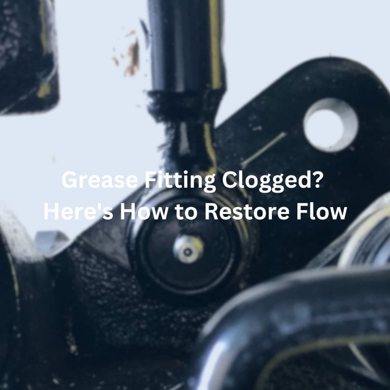
Grease Fitting Clogged? Here's How to Restore Flow

Table of Contents

Introduction

Imagine you’re in the middle of a crucial maintenance task on your heavy machinery, and just as you start to pump grease into a fitting, you hit an impasse—a clogged grease fitting. This common yet vexing problem can lead to increased wear and tear on your equipment, reducing its efficiency and lifespan.  In this post, we will delve into the causes of clogged grease fittings, how to diagnose and fix them, and essential preventative maintenance tips to keep your machinery in top condition.

Understanding Grease Fittings

Definition and Purpose

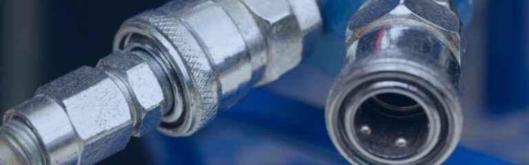
Grease fittings, also known as grease nipples or Zerks, are small mechanical devices designed to allow lubrication to be applied to moving parts of machinery and equipment. These fittings are strategically placed on machinery to ensure that grease can be injected directly into bearing surfaces and other friction points. The primary purpose of grease fittings is to maintain the optimal performance and longevity of machinery by reducing friction and wear, thereby preventing the breakdown of components due to lack of lubrication.

Types of Grease Fittings

NPT grease fitting supplier

There are several types of grease fittings, each designed for specific applications and environments:

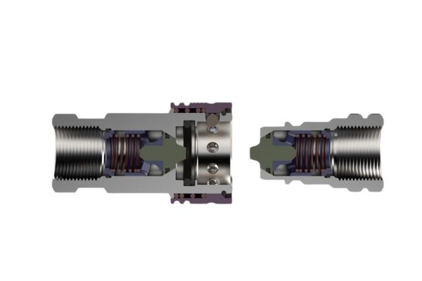
Standard Grease Fittings: The most common type, featuring a ball check valve to prevent dirt from entering and grease from leaking out.

Flush Type Grease Fittings: These sit flush with the surface, making them ideal for applications where protruding fittings might be damaged or obstruct operations.

Button-Head Grease Fittings: Characterized by a larger head, they are used in high-volume applications and are less prone to damage from contaminants.

Angle Grease Fittings: Available in various angles (e.g., 45-degree, 90-degree), these are used in hard-to-reach places where a straight fitting would be impractical.

Common Applications

Grease fittings are ubiquitous across various industries due to their crucial role in maintaining machinery. They are commonly found in:

Automotive Industry: Used in vehicles for lubricating chassis, steering systems, and suspension components.

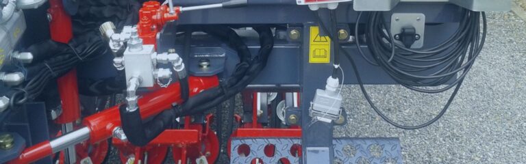
Agriculture: Essential tractors, harvesters, and other farming equipment to keep moving parts well-lubricated.

Manufacturing: Found in a wide range of machinery, including conveyor belts, assembly lines, and robotic arms.

Construction: Used in heavy machinery such as excavators, bulldozers, and cranes to ensure reliable operation under harsh conditions.

Causes of Clogged Grease Fittings

Contamination

One of the primary causes of clogged grease fittings is contamination from dirt, debris, and other foreign particles. When machinery operates in dirty or dusty environments, these contaminants can easily find their way into the grease fitting. The ball check valve, which is designed to keep out dirt, can sometimes fail if not properly maintained, allowing particles to enter the fitting. Once inside, these contaminants mix with the grease and create blockages that impede the flow of lubrication. This contamination not only clogs the fittings but can also cause abrasive wear to the internal components of the machinery, leading to more significant mechanical issues over time. Regular cleaning of the fitting areas and ensuring the grease gun and nozzles are clean can help prevent contamination-related clogs.

Hardened Grease

Another common cause of clogged grease fittings is the hardening of old grease. Over time, grease can degrade, especially if exposed to high temperatures, excessive moisture, or air. This degradation causes the grease to lose its lubricating properties and harden into a solid, wax-like substance that can block the fitting. Hardened grease can be particularly challenging to remove because it creates a solid plug within the fitting, preventing new grease from entering. This is often exacerbated in machinery that is not used regularly, as the grease sits idle for extended periods. To prevent this, it is crucial to use the appropriate type of grease for the operating conditions and to adhere to a regular lubrication schedule that keeps the grease fresh and functional.

grease fitting leaking Topa

Improper Grease Type

Using the wrong type of grease can also lead to clogged fittings. Different types of machinery and operating conditions require specific types of grease, each formulated with unique properties to suit particular applications. For example, high-temperature environments require a grease that can withstand heat without breaking down, while high-load applications need a grease with excellent pressure resistance. Using a grease that is not compatible with the machinery or its operating environment can cause it to break down prematurely, harden, or become too thick to flow through the fittings. Additionally, mixing different types of grease can cause them to react chemically, leading to the formation of clogs. It is essential to consult the machinery’s maintenance manual or a lubrication specialist to select the right grease for each application.

Lack of Maintenance


Irregular maintenance is a significant factor in the clogging of grease fittings. When machinery is not lubricated on a regular schedule, grease can dry out, harden, and block the fittings. Additionally, irregular maintenance means that small issues, such as minor contamination or the beginning stages of grease hardening, go unnoticed and unaddressed, eventually leading to full blockages. Consistent maintenance schedules are crucial to ensuring that grease fittings remain free-flowing and effective. This includes regular inspections, cleaning of fittings, and timely lubrication. Adhering to a maintenance routine helps identify potential problems before they become severe and ensures that all components receive adequate lubrication, thereby extending the life of the machinery.

Diagnosing a Clogged Grease Fitting

Visual Inspection

The first step in diagnosing a clogged grease fitting is a thorough visual inspection. Begin by cleaning the area around the grease fitting with a rag or brush to remove any dirt or debris. This ensures that you can clearly see the fitting and its immediate surroundings. Look for signs of hardened grease around the fitting, which can indicate a blockage. Also, check for any visible cracks or damage to the fitting itself. If the fitting is damaged, it may need to be replaced. Pay attention to any accumulated dirt or debris that could be obstructing the fitting. Ensuring the fitting is clean and intact is a crucial first step in diagnosing a clog.

Grease Gun Resistance

A practical method to detect a clogged grease fitting is by using a grease gun. Attach the grease gun to the fitting and begin to pump grease. Normally, you should feel a consistent resistance as the grease flows into the fitting and lubricates the component. However, if the fitting is clogged, you will notice an unusual amount of resistance or even complete blockage, preventing the grease from flowing. In some cases, the grease gun might also leak around the connection to the fitting, indicating that the grease is not entering the fitting as it should. This resistance is a clear sign that the fitting is clogged and needs attention.

Checking Grease Flow

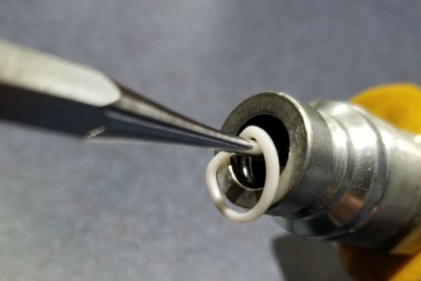
After suspecting a clog based on visual inspection and grease gun resistance, the next step is to check the grease flow through the fitting. To do this, you can use a small wire or a fitting cleaning tool to clear any obvious blockages. Insert the wire into the fitting to see if it encounters any resistance or blockage. If the wire does not pass through easily, this confirms the presence of a clog. Alternatively, if you have a grease fitting cleaner, you can attach it to the fitting and attempt to force a small amount of lubricant through it. Observe if the grease exits the fitting from the other side, indicating a clear passage. If the grease does not flow, the fitting is still blocked and may require further cleaning or even replacement.

Step-by-Step Guide to Unclogging a Grease Fitting

Preparation

Before you start unclogging a grease fitting, it’s essential to prepare both the area and the necessary tools. Begin by gathering the tools and materials you’ll need: a grease gun, grease fitting cleaner, wire brush, cleaning solvent, a small wire or pin, safety gloves, and safety glasses. Ensure the machinery is turned off and cooled down to prevent accidents. Clean the area around the grease fitting with a cloth to remove surface dirt and debris. This step is crucial to avoid introducing new contaminants into the fitting. Lay down a protective sheet or container to catch any grease or debris that might be expelled during the cleaning process. Having everything ready and organized will make the process smoother and more efficient.

Cleaning the Fitting

Once the area is prepared, focus on cleaning the exterior of the grease fitting. Use a wire brush to scrub away any hardened grease, dirt, or debris from around the fitting. This step ensures that when you begin the unclogging process, you don’t inadvertently push external contaminants further into the fitting. After brushing, apply a cleaning solvent to dissolve any remaining grease or grime. Wipe the fitting with a clean rag to remove the solvent and any loosened debris. At this point, the exterior of the fitting should be free of dirt and ready for the next steps.

Using a Grease Fitting Cleaner

A grease fitting cleaner is a specialized tool designed to clear blockages from grease fittings. To use it, first, ensure that the cleaner is filled with a compatible solvent or light oil. Attach the cleaner’s nozzle to the grease fitting, ensuring a secure and tight fit. Once attached, press the cleaner’s handle or plunger to inject the solvent into the fitting. This action should force the solvent through the fitting, breaking up and dissolving the clog. Repeat this process several times, if necessary, to ensure the blockage is thoroughly cleared. Be patient and persistent, as stubborn clogs might take a few attempts to break up completely.

Grease Fitting Clogged fix

Flushing the Fitting

After using the grease fitting cleaner, the next step is to flush out any remaining old grease and contaminants. Attach a grease gun filled with the appropriate type of grease to the fitting. Begin pumping grease into the fitting slowly. Initially, you might see some old, contaminated grease being expelled from the fitting. Continue pumping until you see clean, new grease coming out. This process ensures that all the old grease and any dissolved contaminants are pushed out, leaving only fresh grease inside the fitting. If the grease still does not flow, repeat the cleaning process or consider using a small wire to manually dislodge any remaining blockage.

Testing the Fitting

Once you believe the clog has been cleared and fresh grease is flowing, it’s crucial to test the fitting to ensure it’s fully functional. Start by detaching the grease gun and cleaning any expelled grease from around the fitting. Reattach the grease gun and pump a small amount of grease into the fitting. Observe whether the grease flows smoothly into the fitting and reaches the intended lubrication point. Check the machinery’s components to confirm that the grease is properly lubricating the moving parts. If the grease flows without resistance and reaches the necessary areas, the fitting is successfully unclogged. If there’s still resistance or the grease doesn’t flow correctly, repeat the previous steps or consider replacing the fitting if it appears damaged.

Unclogging a grease fitting requires careful preparation, thorough cleaning, and proper use of tools like grease fitting cleaners and grease guns. By following these steps, you can effectively clear blockages and ensure that your machinery remains well-lubricated and operates smoothly. Regular maintenance and proper lubrication are key to preventing clogs and extending the life of your equipment.

Preventative Maintenance Tips  

Regular Inspection

Regular inspections are crucial for maintaining the functionality of grease fittings and preventing clogs. During inspections, check each grease fitting for signs of dirt, debris, or hardened grease around the nozzle. Look for any visible damage to the fittings, such as cracks or wear, which can lead to leaks and contamination. Also, observe the condition of the grease itself; if it appears discolored or contaminated, it might indicate a problem. Regular inspections help identify potential issues early, allowing you to address them before they cause significant damage.

Proper Grease Selection

Choosing the right type of grease for your machinery is essential to prevent clogs and ensure effective lubrication. Different types of machinery and operating conditions require specific greases with unique properties. Consider factors such as temperature, load, speed, and environmental conditions when selecting grease. High-temperature environments, for instance, require grease with high thermal stability, while high-load applications need grease with superior pressure resistance. Consult your machinery’s maintenance manual or a lubrication specialist to determine the appropriate grease type. Using the correct grease not only enhances lubrication efficiency but also reduces the risk of grease hardening and clogging the fittings.

Routine Cleaning

Incorporating routine cleaning into your maintenance schedule is vital to keep grease fittings free from dirt and debris. Clean the fittings regularly using a wire brush and cleaning solvent to remove any accumulated grease and contaminants. Pay special attention to fittings in dirty or dusty environments, as they are more prone to clogging. After cleaning, inspect the fittings for any signs of wear or damage. Routine cleaning helps maintain the integrity of the fittings and ensures that the grease flows smoothly. Additionally, keeping the grease gun and nozzles clean prevents the introduction of new contaminants during lubrication.

Conclusion

In conclusion, maintaining free-flowing grease fittings is crucial for the optimal performance and longevity of your machinery. We’ve covered the importance of regular inspections, choosing the right grease, routine cleaning, and setting up a scheduled lubrication plan. By following these preventative maintenance tips, you can prevent clogs, reduce downtime, and ensure your equipment operates smoothly. Implement these practices in your maintenance routine and share your experiences to help others in the industry. For further assistance and detailed guides, visit our additional resources or contact our support team for professional advice.

FAQ

Grease fittings can clog due to contamination from dirt and debris, hardened grease, using the wrong type of grease, or lack of regular maintenance.

It’s recommended to inspect grease fittings during each routine maintenance session or at least once a month, depending on the operating conditions of your machinery.

The type of grease you should use depends on your machinery’s operating conditions, such as temperature, load, and speed. Consult your machinery’s maintenance manual or a lubrication specialist for the best choice.

Signs of a clogged grease fitting include excessive resistance when using a grease gun, no grease flow, and visible contamination or hardened grease around the fitting.

You’ll need a grease gun, grease fitting cleaner, wire brush, cleaning solvent, a small wire or pin, and safety equipment like gloves and safety glasses.

Prevent clogging by conducting regular inspections, using the correct grease, performing routine cleaning, and maintaining a scheduled lubrication plan.

Hydraulic Quick Coupler Won't Connect Here’s What to Do

Hydraulic Quick Coupler Won’t Connect? Here’s What to Do

Hydraulic Quick Coupler Won't Connect? Here’s What to Do

Table of Contents

Introduction

Imagine you’re in the middle of a critical operation on a construction site, a farm, or a manufacturing plant, and suddenly, your hydraulic quick coupler refuses to connect. Every minute of downtime translates to lost productivity and increased costs. In this post, we will delve into the common reasons why hydraulic quick couplers might fail to connect, provide a step-by-step troubleshooting guide, and offer preventive measures to avoid future issues.

Understanding Hydraulic Quick Couplers

Definition and Function

Hydraulic quick couplers are specialized connectors designed to quickly and easily join or separate hydraulic lines without the need for tools. These couplers are crucial in hydraulic systems, allowing for the swift connection and disconnection of hoses, which facilitates maintenance, equipment swaps, and emergency repairs. They are engineered to withstand high pressures and provide a secure, leak-free connection that maintains the integrity and efficiency of the hydraulic system.

Types of Hydraulic Quick Couplers

Hydraulic quick couplers come in various types, each suited to different applications and standards:

ISO A Couplers: These are the most common type, featuring a poppet valve design that is widely used in agricultural and industrial applications. They are known for their versatility and reliability in medium-pressure applications.

ISO B Couplers: Featuring a ball valve design, these couplers are commonly used in applications where resistance to dirt and debris is essential. They are ideal for high-pressure systems and are often found in construction and industrial machinery.

Flush Face Couplers: Designed to minimize fluid loss and prevent the ingress of air and contaminants, these couplers are popular in sensitive environments such as food processing and medical equipment. Their smooth face design makes cleaning easy and ensures a clean connection.

Flat Face Couplers: Similar to flush face couplers, these are used in environments where preventing spillage is critical. They are typically used in applications such as skid steer loaders and other heavy equipment.

Flat quick release hydraulic fitting

Applications

Hydraulic quick couplers are integral to various industries, providing efficiency and safety in their operations:

Construction: Quick couplers are used to connect hydraulic attachments like hammers, drills, and buckets, allowing for rapid changes and increased productivity on-site.

Agriculture: In farming equipment, quick couplers facilitate the easy swapping of implements such as plows, harrows, and sprayers, enhancing the versatility and efficiency of agricultural machinery.

Manufacturing: In industrial settings, hydraulic quick couplers are essential for maintaining and modifying production lines, ensuring minimal downtime, and maximizing operational efficiency.

Why Hydraulic Quick Couplers Won't Connect

Contamination and Debris

One of the most common reasons hydraulic quick couplers fail to connect is contamination from dirt, dust, and debris. When contaminants infiltrate the coupler, they can obstruct the internal mechanisms, preventing a secure connection. These particles can accumulate over time, especially in harsh environments like construction sites or farms, where equipment is frequently exposed to the elements. To mitigate this issue, regular cleaning and the use of protective caps when couplers are not in use are essential practices.

Wear and Tear

Hydraulic quick couplers are subject to significant mechanical stress and pressure, leading to natural wear and tear over time. The seals, valves, and connecting surfaces can degrade, resulting in poor alignment and an inability to form a proper seal. When parts become excessively worn, the coupler may not lock correctly, causing fluid leaks or complete disconnection. Regular inspection and timely replacement of worn components are crucial to maintaining the reliability of the hydraulic system.

leaky quick coupling

Misalignment

Proper alignment is critical for the effective connection of hydraulic quick couplers. Misalignment can occur if the hoses or equipment are not properly positioned, leading to an imperfect connection that can result in fluid leaks or system inefficiencies. Ensuring that both coupler ends are aligned correctly and applying even pressure during connection can prevent alignment issues. Additionally, checking for any obstructions or bends in the hoses can help maintain proper alignment.

Pressure Issues

Hydraulic systems operate under high pressure, and unequal or excessive pressure can hinder the connection of quick couplers. If the pressure is not adequately relieved before attempting to connect, the force can prevent the couplers from locking together. This is particularly common in systems with residual pressure trapped in the lines. To address this, it’s important to relieve system pressure by shutting off the hydraulic system and actuating the control valve to release any trapped pressure before connecting or disconnecting the couplers.

Damaged Components

Physical damage to the couplers or hoses is another prevalent issue that can prevent connection. Damage can occur due to rough handling, accidental impacts, or exposure to harsh conditions. Common damages include cracks, bends, or deformations in the quick coupler body and hoses and damaged seals or locking mechanisms. Regular inspection for signs of damage and prompt repair or replacement of affected components can prevent connection problems and ensure the safe operation of the hydraulic system.

Detailed Troubleshooting Guide

Initial Checks

Visual Inspection

Steps to Visually Inspect the Couplers for Obvious Issues:

Disconnect the System: Ensure the hydraulic system is turned off and depressurized.

Examine Coupler Surfaces: Look for cracks, dents, or deformities on the coupler surfaces.

Check for Debris: Inspect the interior and exterior of the couplers for any dirt, dust, or debris.

Inspect Seals and O-rings: Look for signs of wear, cracks, or damage on the seals and O-rings.

Test Movement: Ensure that the coupler’s moving parts (such as sleeves or valves) move smoothly without sticking.

Cleanliness

Methods to Clean Couplers and Remove Debris:

Use Compressed Air: Blow out any loose debris from the coupler using compressed air.

Clean with Solvent: Use a clean cloth and a mild solvent to wipe down the coupler parts, removing any grease or stubborn dirt.

Brush for Tough Debris: For more stubborn contaminants, use a soft-bristle brush to clean crevices and internal components.

Dry Thoroughly: Ensure the coupler is completely dry before attempting to reconnect it.

Hydraulic Quick Coupler clean

Compatibility Check

Ensuring Couplers are Compatible with Each Other:

Check Manufacturer Specifications: Verify that both couplers are designed to work together by checking the manufacturer’s specifications.

Match Types and Sizes: Ensure that the couplers are of the same type (ISO A, ISO B, etc.) and size.

Verify Pressure Ratings: Make sure the pressure ratings of both couplers are compatible to avoid mismatched performance.

Addressing Pressure Problems

Relieving Pressure

Techniques to Relieve Hydraulic Pressure Before Attempting Connection:

Turn Off Equipment: Shut down the hydraulic system completely.

Actuate Control Valves: Move the control valves through all positions to release any trapped pressure in the lines.

Use Pressure Relief Valves: Engage the system’s pressure relief valves to ensure all residual pressure is released.

Check Pressure Gauges: Confirm that the pressure gauges read zero before attempting to connect the couplers.

Checking System Pressure

How to Measure and Adjust System Pressure:

Use a Pressure Gauge: Attach a pressure gauge to the system to get an accurate reading of the current pressure.

Adjust Pressure Settings: If the pressure is too high, use the system’s controls to lower it to the recommended level.

Monitor Pressure Fluctuations: Ensure that the pressure remains stable during operation and does not exceed the coupler’s specifications.

Replacing O-Rings and Seals

Gather Tools and Parts

Ensure You Have the Correct Replacement O-Rings and Seals, Along with Necessary Tools: Before starting the replacement process, gather all required tools and parts. This typically includes a pick or seal removal tool, a set of new O-rings and seals that match the specifications of your coupler, hydraulic oil for lubrication, and cleaning supplies. Refer to the manufacturer’s manual to confirm the exact size and type of seals needed.

Remove Old Seals

Carefully Remove the Old Seals and O-rings Using a Pick or Similar Tool: Use a Pick or Seal removal tool to gently pry out the old seals and O-rings. Take care not to scratch or damage the grooves where the seals sit, as this can affect the performance of the new seals.

quick coupler O-ring seal fix

Clean Seal Grooves

Clean the Grooves Where the Seals Sit to Remove Any Residue or Debris: Once the old seals are removed, thoroughly clean the seal grooves. Use a clean cloth and an appropriate solvent to remove any residue, dirt, or old seal material. Ensuring the grooves are clean is essential for the new seals to sit correctly and function effectively.

Install New Seals

Carefully Place the New Seals and O-Rings into Their Respective Grooves, Ensuring They Sit Correctly: Gently press the new seals and O-rings into their grooves, making sure they fit snugly and sit correctly without any twists or kinks. Proper installation is crucial to prevent leaks and ensure the longevity of the seals.

Inspecting Hoses and Fittings

Visual Inspection

Look for Any Signs of Abrasion, Cracks, or Leaks Along the Length of the Hose: During visual inspections, carefully examine the entire length of each hose for signs of wear and damage. Abrasion marks, cracks, or leaks can indicate that the hose is compromised and may fail under pressure. Pay special attention to areas near fittings and bends where damage is more likely to occur.

Check Fittings

Ensure That Fittings Are Not Damaged and Are Securely Attached to the Hoses: Inspect the fittings at the ends of the hoses to ensure they are not damaged, corroded, or loose. Damaged fittings can cause leaks and affect the performance of the hydraulic system. Tighten any loose fittings according to the manufacturer’s specifications, but be careful not to overtighten, as this can cause damage.

Flex Test

Gently Flex the Hoses to Check for Any Stiffness or Brittleness, Which Can Indicate Internal Damage: Gently flex the hoses along their length to feel for any stiffness or brittleness, which can be signs of internal damage or aging. Flexible hoses should bend smoothly without any resistance or cracking sounds. Stiff or brittle hoses are at a higher risk of failure and should be replaced immediately.

Replace Damaged Hoses

If Any Damage Is Found, Replace the Hoses and Fittings Immediately to Maintain System Integrity: If any signs of damage are detected during inspections, replace the affected hoses and fittings immediately. Using damaged components can lead to system failure, safety hazards, and costly downtime.

Preventive Measures

Regular Maintenance

Importance of Scheduled Maintenance to Prevent Issues: Establish a regular maintenance schedule to inspect, clean, and service all hydraulic components. Regular maintenance helps to identify and address potential problems before they lead to significant issues, ensuring the reliability and longevity of your hydraulic system.

Proper Storage

Best Practices for Storing Hydraulic Components to Avoid Damage: Proper storage of hydraulic components is crucial to prevent damage and extend their lifespan. Store couplers, hoses, and other components in a clean, dry environment away from direct sunlight and extreme temperatures. Use protective caps and covers to keep contaminants out and organize components to avoid unnecessary stress or deformation. Following these best practices can help maintain the performance and reliability of your hydraulic system.

Conclusion

In summary, effectively troubleshooting and maintaining hydraulic quick couplers involves regular inspections, proper cleaning, and ensuring compatibility and alignment. Addressing pressure issues and promptly replacing worn or damaged parts are crucial steps in preventing connection problems. Emphasizing the importance of routine maintenance and storage best practices can significantly enhance the reliability and longevity of your hydraulic systems.

FAQ

Start by checking for contamination, wear and tear, and ensuring proper alignment. Relieve any residual pressure in the system and inspect for damaged components.

Regular inspections should be scheduled based on the usage frequency and operating conditions, typically ranging from daily to monthly.

Common types include ISO A, ISO B, flush face, and flat face couplers, each designed for specific applications and standards.

Use protective caps when couplers are not in use, regularly clean them, and ensure the working environment is as clean as possible.

Look for cracks, deformities, worn seals, and O-rings, as well as any stiffness or brittleness in hoses.

Turn off the hydraulic system, actuate control valves to release trapped pressure, and ensure pressure gauges read zero before attempting to connect the couplers.

How to Install Quick Coupler on Excavator

How to Install Quick Coupler on Excavator

How to Install Quick Coupler on Excavator

Introduction

Quick couplers have revolutionized the construction and excavation industries by significantly enhancing the efficiency and versatility of excavators. These devices allow operators to quickly and easily change attachments, such as buckets, breakers, and grapples, without the need for manual intervention or additional tools. This not only saves valuable time but also reduces labor costs and minimizes downtime, allowing projects to be completed more swiftly and effectively. The primary aim of this post is to provide a comprehensive, step-by-step guide for installing a quick coupler on an excavator.

Preparation for Installation

Safety Precautions

Ensuring safety during the installation of a quick coupler on an excavator is paramount. Taking the right precautions can prevent accidents and injuries, creating a secure work environment for everyone involved.

Personal Protective Equipment (PPE) Requirements:

Before beginning the installation, it’s crucial to equip yourself and your team with the appropriate personal protective equipment (PPE). This typically includes:

Hard Hats: Protects the head from potential impacts.

Safety Glasses or Goggles: Shields eyes from debris and hydraulic fluid splashes.

Work Gloves: Provides grip and protection for hands while handling tools and equipment.

Steel-Toed Boots: Offers foot protection against heavy falling objects.

High-Visibility Vests: Ensures that all team members are visible in the work area.

Safety Checks and Environment Setup:

Before starting the installation process, conduct thorough safety checks and ensure the environment is set up appropriately. Key steps include:

Inspect the Work Area: Clear the area of any obstacles, debris, or unnecessary equipment that could pose tripping hazards or obstruct the workflow.

Stabilize the Excavator: Ensure the excavator is on level ground and the parking brake is engaged. Use chocks if necessary to prevent any unintended movement.

Hydraulic System Deactivation: Depressurize the hydraulic system to avoid accidental releases of high-pressure fluid, which can cause serious injuries.

Communication Plan: Establish clear communication protocols with all team members to ensure everyone is aware of their roles and responsibilities during the installation process.

Required Tools and Equipment

Having the right tools and equipment on hand is essential for a smooth and efficient installation of the quick coupler.

List of Tools Needed:

Gather the following tools before starting the installation:

Wrenches: Various sizes to accommodate different bolts and fittings.

Screwdrivers: Both flathead and Phillips for securing components.

Socket Set: For loosening and tightening nuts and bolts.

Torque Wrench: Ensures that bolts are tightened to the manufacturer’s specifications.

Pliers: Useful for gripping and manipulating small parts.

Specific Equipment:

In addition to general tools, certain specialized equipment may be necessary:

Hydraulic Hoses: New hoses may be required to connect the quick coupler to the excavator’s hydraulic system.

Fittings and Adapters: Ensure compatibility between the quick coupler and the excavator’s existing hydraulic setup.

Lubricants: High-quality lubricants to ensure smooth operation and reduce wear on moving parts.

Cleaning Supplies: Clean rags, solvents, and brushes to prepare the attachment points and hydraulic connections.

Understanding the Specific Model and Specifications

Each quick coupler model may have unique features and requirements. Take the time to familiarize yourself with:

Model-Specific Instructions: Differences in installation steps or additional components that need to be considered.

Technical Specifications: Information about hydraulic pressure limits, torque settings for bolts, and recommended attachment weights.

Compatibility Information: Ensure that the quick coupler is compatible with your excavator model and any attachments you plan to use.

Removing the Existing Attachment

Positioning the Excavator

Proper positioning of the excavator is crucial for the safe and efficient removal of the existing attachment. The ideal location and positioning ensure stability and provide ample working space for the installation process.

Ideal Location and Positioning for Safe Removal:

Stable Ground: Position the excavator on firm, level ground to prevent any movement or tipping during the removal process. Avoid soft or uneven terrain.

Clear Area: Ensure the work area is free of obstacles, debris, and other equipment that could interfere with the process or pose tripping hazards.

Parking Brake and Chocks: Engage the parking brake to secure the excavator. Use wheel chocks to provide additional stability, especially if the excavator is positioned on a slight incline.

Boom and Arm Position: Lower the boom and arm to a comfortable working height. The attachment should be close to the ground but not in contact with it, allowing for easy access to the connecting points and hydraulic lines.

Hydraulic Quick Coupler installation

Disconnecting Hydraulic Lines

Safely disconnecting the hydraulic lines is a critical step to prevent accidents and ensure the integrity of the hydraulic system.

Steps to Safely Disconnect Existing Hydraulic Lines:

Depressurize the System: Before disconnecting any hydraulic lines, ensure the hydraulic system is fully depressurized. This can typically be done by turning off the excavator and operating the controls to release any residual pressure.

Locate the Hydraulic Lines: Identify the hydraulic lines connected to the attachment. These are usually color-coded or marked for easy identification.

Prepare for Disconnection: Use clean rags or absorbent pads to catch any residual hydraulic fluid that may spill during disconnection. Position a drip tray under the connection points to collect any fluid.

Loosen the Fittings: Using the appropriate wrenches, carefully loosen the fittings on the hydraulic lines. Start with the smaller lines and move to the larger ones to minimize the risk of fluid spillage.

Disconnect the Lines: Once the fittings are loosened, carefully disconnect the hydraulic lines. Cap the ends of the lines and the ports on the attachment to prevent contamination and fluid loss.

Precautions to Avoid Hydraulic Fluid Spillage:

Use Absorbent Pads: Place absorbent pads or rags around the connection points to catch any escaping fluid.

Work Slowly: Disconnect the lines slowly to give the residual fluid time to drain without splashing.

Cap the Ends: Immediately cap the ends of the hydraulic lines and the attachment ports to prevent further leakage and contamination.

Clean Up Spills: Have a spill kit on hand to quickly clean up any hydraulic fluid that spills onto the ground.

Detaching the Current Attachment

Once the hydraulic lines are safely disconnected, the next step is to detach the current attachment from the excavator.

Procedures for Detaching the Existing Bucket or Attachment:

Inspect the Attachment Points: Identify the pins or bolts securing the attachment to the excavator’s arm. Inspect them for any signs of wear or damage that might complicate the removal process.

Remove the Retaining Pins or Bolts: Using the appropriate tools, remove the retaining pins or bolts. If they are stuck or rusted, apply penetrating oil and allow it to sit for a few minutes before attempting removal.

Support the Attachment: Before fully removing the pins or bolts, ensure the attachment is supported to prevent it from falling suddenly. You can use a lifting device or have a team member hold the attachment steady.

Release the Attachment: Carefully release the attachment from the excavator arm. If the attachment is heavy or unwieldy, use a lifting device like a crane or forklift to lower it to the ground safely.

Handling and Storing the Detached Parts:

Secure the Attachment: Once detached, move the attachment to a designated storage area. Ensure it is placed on a stable surface to prevent tipping or rolling.

Clean the Attachment: Clean any dirt or debris from the attachment, particularly around the connection points, to maintain its condition and prevent contamination of the quick coupler.

Label and Organize: If you plan to reuse the attachment, label it clearly and store it in an organized manner with other compatible parts.

Inspect for Damage: Check the detached attachment for any signs of wear or damage that may need to be addressed before future use.

Installing the Quick Coupler

Mounting the Coupler to the Excavator Arm

Mounting the quick coupler onto the excavator’s arm is a crucial step that requires precision and attention to detail. Ensuring the coupler is properly aligned and securely attached will guarantee its effective operation and longevity.

Aligning the Coupler with the Excavator Arm:

Position the Coupler: Place the quick coupler near the excavator arm’s attachment points. Ensure that the coupler is oriented correctly, with the hydraulic connections easily accessible.

Align the Holes: Carefully align the mounting holes on the quick coupler with those on the excavator’s arm. This alignment is critical for the stability and functionality of the coupler.

Use Guide Pins: If available, use guide pins to help align the holes accurately. This can make it easier to insert the bolts or pins later on.

Securing the Coupler with Bolts and Nuts:

Insert the Bolts: Once the holes are aligned, insert the mounting bolts through the coupler and the excavator arm. Ensure that the bolts are the correct size and grade as specified by the manufacturer.

Hand-Tighten First: Initially, hand-tighten the bolts to hold the coupler in place. This allows for any minor adjustments before fully securing the bolts.

Use a Torque Wrench: Using a torque wrench, tighten the bolts to the specified torque setting provided in the manufacturer’s guidelines. This ensures the bolts are neither too loose nor too tight, preventing potential damage or loosening during operation.

Double-Check Tightness: After securing all bolts, double-check their tightness to ensure the coupler is firmly attached and there are no loose connections.

Install Quick Coupler on Excavator

Connecting Hydraulic Lines

Properly connecting the hydraulic lines is essential for the coupler’s operation. Ensuring leak-free connections will maintain the hydraulic system’s integrity and performance.

Attaching the Hydraulic Lines to the Quick Coupler:

Identify the Connections: Identify the hydraulic ports on the quick coupler. These are usually marked or labeled for easy identification.

Prepare the Lines: Ensure the hydraulic lines are clean and free from any debris. Contaminants can damage the hydraulic system and reduce its efficiency.

Attach the Lines: Connect the hydraulic lines to the appropriate ports on the quick coupler. Hand-tighten the fittings first to ensure they are correctly threaded and aligned.

Secure the Fittings: Using the appropriate wrenches, tighten the hydraulic fittings securely. Avoid overtightening, which can damage the fittings and cause leaks.

Ensuring Proper Connections to Avoid Leaks:

Inspect the Connections: Visually inspect each hydraulic connection to ensure there are no gaps or misalignments.

Use Hydraulic Sealant: If recommended by the manufacturer, apply a hydraulic sealant to the threads of the fittings before connecting them. This can help create a leak-proof seal.

Check for Flexibility: Ensure the hydraulic lines have enough slack to accommodate the movement of the quick coupler and the excavator arm. Avoid overly tight or stretched lines, which can lead to leaks or ruptures.

Testing the Hydraulic System

Before fully utilizing the quick coupler, it’s important to conduct initial tests to ensure everything is functioning correctly and there are no leaks.

Initial Tests to Ensure the Coupler is Functioning Correctly:

Power Up the Excavator: Start the excavator and allow the hydraulic system to pressurize. Monitor the system for any immediate issues or warning signals.

Operate the Coupler: Use the excavator controls to operate the quick coupler. Test its ability to open, close, and lock onto attachments. Ensure smooth and responsive movements.

Monitor Hydraulic Pressure: Check the hydraulic pressure readings to ensure they are within the manufacturer’s specified range for the quick coupler.

Checking for Leaks and Making Necessary Adjustments:

Inspect the Connections: While operating the quick coupler, inspect all hydraulic connections for signs of leaks. Look for drips, wet spots, or hissing sounds that indicate escaping fluid.

Tighten as Needed: If leaks are detected, power down the excavator and depressurize the hydraulic system before tightening any loose fittings. Reapply hydraulic sealant if necessary.

Retest the System: After making adjustments, retest the hydraulic system to confirm that the leaks have been resolved and the coupler is operating correctly.

Repeat Checks: Perform these checks periodically during the initial hours of operation to ensure that the quick coupler remains secure and leak-free.

Attaching New Attachments

Securing Attachments

Properly securing the new attachment to the quick coupler is essential to ensure safe and efficient operation. This process involves locking the attachment into place and verifying its stability.

Steps to Lock New Attachments into the Quick Coupler:

Position the Attachment: Place the attachment in a stable position where it can be easily accessed by the quick coupler. Align the attachment’s connection points with the coupler’s locking mechanism.

Engage the Coupler: Use the excavator controls to move the quick coupler into position over the attachment. Ensure that the coupler’s hooks or pins align with the attachment’s mounting points.

Lock the Attachment: Activate the quick coupler’s locking mechanism to secure the attachment. This may involve hydraulic or manual locking systems. Ensure the locking pins or hooks fully engage with the attachment.

Check Alignment: Visually inspect the connection to ensure the attachment is properly aligned and securely locked into place.

Verifying the Security of the Attachment:

Perform a Visual Inspection: Check that the locking pins or hooks are fully engaged and that there is no visible gap between the coupler and the attachment.

Conduct a Physical Check: If possible, manually move the attachment to ensure it is firmly secured and does not wobble or shift.

Tighten Any Bolts: If the attachment has additional securing bolts, use the appropriate tools to tighten them to the manufacturer’s recommended torque settings.

Double-Check Hydraulic Connections: If the attachment requires hydraulic connections, ensure all fittings are tight and there are no leaks.

Conclusion

To achieve the best results, it’s important to follow this comprehensive guide carefully. Each step has been outlined to provide you with the necessary information to install the quick coupler correctly and safely. Adhering to these guidelines will not only enhance the performance of your excavator but also extend the life of your equipment. We encourage you to share your experiences, feedback, or any questions you might have about the installation process. Your insights and inquiries can help us improve this guide and address any challenges you might face.

FAQ

There are three main types of quick couplers: mechanical, hydraulic, and manual. Mechanical couplers require a wrench to operate, hydraulic couplers use the excavator’s hydraulic system for attachment changes, and manual couplers involve physical engagement and disengagement of attachments.

Not all attachments are compatible with every quick coupler. It’s essential to check the manufacturer’s specifications to ensure the attachment fits the coupler’s size and connection type. Compatibility ensures safe and efficient operation.

Regular maintenance should be performed at least once a month or according to the manufacturer’s recommendations. This includes checking for wear and tear, lubricating moving parts, and inspecting hydraulic connections for leaks.

If you notice hydraulic fluid leaks, stop the operation immediately and depressurize the system. Inspect the hydraulic connections for loose fittings or damaged hoses. Tighten fittings or replace damaged components as necessary before resuming operation.

Ensure that all bolts and nuts are tightened to the manufacturer’s specified torque settings using a torque wrench. Double-check the alignment of the coupler with the excavator arm and visually inspect the connection points for any gaps or misalignments.

Yes, following the manufacturer’s manual is crucial. It provides specific instructions and safety warnings that are tailored to your quick coupler model. Adhering to these guidelines ensures proper installation and avoids voiding any warranties.

How to Identify Hydraulic Quick Coupler

How to Identify Hydraulic Quick Coupler

How to Identify Hydraulic Quick Coupler?

Introduction

Have you ever faced downtime or equipment failure because of an incompatible hydraulic quick coupler? Identifying the right hydraulic quick coupler is crucial for the seamless operation of your hydraulic systems, preventing costly interruptions and ensuring safety. Hydraulic quick couplers are essential components in hydraulic systems, allowing for quick and efficient connections and disconnections of fluid lines. This post aims to provide a comprehensive guide on how to correctly identify hydraulic quick couplers. Accurate identification not only enhances system performance but also ensures compatibility and safety, reducing the risk of leaks, equipment damage, and operational inefficiencies.

Understanding Hydraulic Quick Couplers

Hydraulic quick couplers are specialized connectors used in hydraulic systems to facilitate the quick and easy connection and disconnection of hydraulic lines. These couplers are designed to prevent fluid leakage and contamination during the connection process, ensuring a secure and efficient transfer of hydraulic fluid. Quick couplers are commonly used in a variety of industries, including construction, agriculture, and manufacturing, where they help to enhance operational efficiency by reducing downtime associated with connecting and disconnecting hydraulic equipment.

Types of Hydraulic Quick Couplers

ISO A and B

ISO A and B quick couplers are standardized couplers that adhere to specific international standards set by the International Organization for Standardization (ISO). These couplers are widely used due to their compatibility with equipment from different manufacturers. ISO A couplers feature a ball valve design, which provides a reliable seal and is suitable for general hydraulic applications. ISO B couplers, on the other hand, use a poppet valve design, offering a higher flow capacity and better performance in high-pressure applications.

Flat Face Couplers

Flat face couplers are designed with a flat sealing surface, which minimizes fluid loss and reduces the risk of contamination during connection and disconnection. These couplers are particularly well-suited for applications where cleanliness is critical, such as in construction and agricultural equipment. The flat face design also makes them easier to clean, further enhancing their suitability for environments where maintaining hydraulic fluid purity is essential.

High Flow Couplers

High flow couplers are engineered to provide a higher flow rate compared to standard quick couplers, making them ideal for applications requiring a significant volume of hydraulic fluid transfer. These couplers are commonly used in heavy machinery and equipment that demands high flow capacity to operate efficiently. The design of high flow couplers typically includes larger internal passageways to accommodate increased fluid flow while maintaining a secure and leak-free connection.

10,000 PSI High Pressure Screw To Connect Hydraulic Quick Coupling

Screw-to-Connect Couplers

Screw-to-connect couplers are designed with a threaded connection mechanism, providing a robust and secure connection that can withstand high pressure and severe mechanical stresses. These couplers are ideal for applications involving high vibration or where accidental disconnection could lead to significant operational hazards. The screw-to-connect design ensures that the couplers remain securely fastened, even under challenging conditions, making them suitable for heavy-duty industrial applications.

Components of Hydraulic Quick Couplers

Female and Male Halves

Hydraulic quick couplers consist of two main parts: the female half and the male half. The female half typically includes a locking mechanism that securely holds the male half in place when connected. The male half features a protruding end that fits into the female half, creating a secure and leak-free connection. Both halves are designed to align perfectly, ensuring a tight seal and efficient fluid transfer.

Seals and O-rings

Seals and O-rings are critical components of hydraulic quick couplers, providing a reliable seal that prevents hydraulic fluid from leaking during operation. These components are typically made from high-quality materials such as nitrile, Viton, or polyurethane, chosen for their resistance to hydraulic fluids and their ability to maintain a tight seal under high pressure. Proper maintenance and regular replacement of seals and O-rings are essential to ensure the longevity and performance of the couplers.

Valves

Valves within hydraulic quick couplers control the flow of hydraulic fluid. Different types of valves, such as ball valves and poppet valves, are used depending on the specific application requirements. Ball valves provide a reliable and simple mechanism for fluid control, while poppet valves offer higher flow capacity and better sealing performance under high-pressure conditions. The choice of valve type depends on factors such as flow rate, pressure, and the need for contamination control.

quick Coupling machine drawing

Dust Caps

Dust caps are protective covers used to shield the connection points of hydraulic quick couplers from dirt, debris, and contaminants when the couplers are not in use. These caps are essential for maintaining the cleanliness and integrity of the hydraulic system, preventing foreign particles from entering the fluid lines and causing damage or reduced performance. Dust caps are typically made from durable materials like plastic or rubber and are designed to fit securely over the coupler ends.

Visual Identification

Shape and Design

Hydraulic quick couplers come in various shapes and designs, each tailored to specific applications and performance requirements. Understanding the different shapes and designs is crucial for correct identification and application.

ISO A and B Couplers: These typically have a cylindrical shape with distinct locking mechanisms that are easy to identify by their uniform structure. ISO A couplers usually feature a ball valve, whereas ISO B couplers often have a poppet valve design.

Flat Face Couplers: These are characterized by their flat, smooth sealing surface, which distinguishes them from other couplers. The flat face design minimizes fluid loss and contamination, making them easily recognizable.

High Flow Couplers: Often larger in size to accommodate higher flow rates, these couplers can be identified by their broader internal passageways and robust build.

Screw-to-Connect Couplers: These have a threaded connection mechanism, which is a key visual feature. The presence of external threads on the male half and corresponding internal threads on the female half make them stand out.

Color Coding

Color coding is a practical method for quickly identifying the type and application of hydraulic quick couplers. Manufacturers often use specific colors to denote different series, pressure ratings, or fluid compatibility.

Series Identification: Some manufacturers use distinct colors to differentiate between various series of couplers. For instance, ISO A might be color-coded differently than ISO B.

Pressure Ratings: Different pressure ratings can be indicated by color. For example, low-pressure couplers might be blue, while high-pressure ones could be red.

Fluid Compatibility: Colors can also signify compatibility with specific hydraulic fluids. Green might indicate compatibility with bio-degradable fluids, while yellow could denote compatibility with standard hydraulic oils.

Markings and Labels

Markings and labels on hydraulic quick couplers provide essential information about their specifications and compatibility. Understanding these markings can aid in proper identification and application.

Manufacturer Logos

Most hydraulic quick couplers will have the manufacturer’s logo etched or stamped on the body. This logo not only identifies the brand but often provides a reference for quality and compatibility with other components from the same manufacturer.

Size and Pressure Ratings

Size Markings: Couplers typically have size markings that indicate the diameter of the connection points. These markings are crucial for ensuring that the coupler fits the corresponding hydraulic lines or ports.

Pressure Ratings: Pressure ratings are usually marked on the coupler to denote the maximum operating pressure. This information is vital to prevent overloading the coupler, which could lead to failure or safety hazards. The ratings are often indicated in PSI (pounds per square inch) or bar.

Technical Specifications

Size and Dimensions

Diameter

The diameter of a hydraulic quick coupler is one of the primary specifications used to ensure compatibility with hydraulic systems. It is measured across the coupling’s mating end and is crucial for matching the coupler to the hydraulic hoses and ports. Common diameters include 1/4″, 3/8″, 1/2″, and 3/4″, but many other sizes are available to suit specific applications.

Length

The overall length of a hydraulic quick coupler affects how it fits within a hydraulic system, especially in confined spaces. This dimension is measured from the end of the male half to the end of the female half when connected. The length can vary significantly between different types of couplers and should be considered when designing or modifying hydraulic systems.

Material Composition

Steel

Steel is a common material for hydraulic quick couplers due to its strength and durability. It is suitable for high-pressure applications and environments where mechanical strength is crucial. Steel couplers are often plated with zinc or other coatings to enhance corrosion resistance.

Brass

Brass is used for its excellent corrosion resistance and moderate strength. It is ideal for lower-pressure applications and environments where exposure to water or corrosive fluids is a concern. Brass couplers are commonly found in agricultural and industrial settings.

Stainless Steel

Stainless steel offers superior corrosion resistance and strength, making it suitable for high-pressure and high-corrosion environments, such as marine and chemical processing industries. Stainless steel couplers are also preferred in applications where hygiene is essential, like in food processing.

Pressure Ratings

Maximum Operating Pressure

The maximum operating pressure indicates the highest pressure at which the coupler can safely function during regular use. This specification ensures that the coupler can handle the pressures exerted by the hydraulic system without risk of failure. It is typically measured in PSI (pounds per square inch) or bar. For example, a standard hydraulic quick coupler might have a maximum operating pressure of 5,000 PSI (345 bar).

Burst Pressure

Burst pressure is the pressure at which the coupler will fail catastrophically. This rating is significantly higher than the maximum operating pressure and provides a safety margin to prevent failure under extreme conditions. Burst pressure is a critical specification for ensuring the overall safety and reliability of hydraulic systems. For example, a coupler with a maximum operating pressure of 5,000 PSI might have a burst pressure of 20,000 PSI (1,380 bar).

Functional Identification

Coupling Mechanism

Push-to-Connect Mechanism

Description: Push-to-connect couplers are designed for quick and easy connections. Simply pushing the male half into the female half engages the coupler, which is secured by internal locking mechanisms.

Advantages: Fast connection and disconnection without the need for tools, ideal for applications requiring frequent coupling and uncoupling.

Applications: Commonly used in agricultural, construction, and industrial equipment where speed and ease of use are critical.

Screw-to-Connect Mechanism

Description: Screw-to-connect couplers require the male half to be screwed into the female half, creating a robust and secure connection. The threaded mechanism ensures a tight seal even under high pressure and vibration.

Advantages: Provides a more secure and reliable connection, suitable for high-pressure applications and environments with significant vibration or mechanical stress.

Applications: Ideal for heavy-duty industrial applications, including construction machinery, mining equipment, and hydraulic presses.

high-pressure quick release hydraulic fitting Topa

Valve Types

Ball Valve

Description: Ball valves use a spherical ball with a hole through the center that controls fluid flow. When the valve is open, the hole aligns with the flow path; when closed, the ball rotates to block the flow.

Advantages: Simple and reliable, offering quick operation and good sealing properties.

Applications: Suitable for a wide range of hydraulic systems, including those requiring frequent operation and minimal fluid leakage.

Poppet Valve

Description: Poppet valves use a poppet (a movable seal) that moves perpendicularly to the flow direction to open and close the flow path. The poppet is spring-loaded to ensure a tight seal when closed.

Advantages: Provides a higher flow rate and better sealing under high-pressure conditions compared to ball valves.

Applications: Commonly used in high-pressure applications and where minimal fluid loss and contamination are critical.

Flat Valve

Description: Flat valves, often found in flat-face couplers, have a flat sealing surface that minimizes fluid loss and contamination. The flat design makes them easy to clean and reduces the chance of dirt entering the hydraulic system.

Advantages: Excellent contamination control and minimal fluid loss during connection and disconnection.

Applications: Ideal for applications in construction, agriculture, and environments where cleanliness is paramount.

Flow Rate

How to Identify Based on Flow Rate Specifications

Description: Flow rate is the volume of fluid that passes through the coupler per unit of time, typically measured in gallons per minute (GPM) or liters per minute (LPM).

Identification: Manufacturers provide flow rate specifications for their couplers, which can be found in product datasheets or markings on the coupler itself. These specifications ensure that the coupler can handle the required flow rate without causing significant pressure drops or system inefficiencies.

Importance: Selecting a coupler with the appropriate flow rate is crucial to maintaining system performance and preventing issues such as cavitation or excessive pressure loss.

Interchange Standards

ISO Standards

Description: The International Organization for Standardization (ISO) sets global standards for hydraulic quick couplers, ensuring compatibility and interchangeability between different manufacturers and systems. Common ISO standards include ISO 7241-1 series A and B.

Advantages: Ensures that couplers from different manufacturers can be used interchangeably, providing flexibility and convenience in sourcing and replacing components.

SAE Standards

Description: The Society of Automotive Engineers (SAE) sets standards for hydraulic couplers, particularly in the automotive and aerospace industries. SAE standards ensure that couplers meet specific performance and safety criteria.

Advantages: Assures quality and performance, particularly in high-stress and high-reliability applications.

Conclusion

In this post, we explored the intricacies of identifying hydraulic quick couplers, covering their types, components, technical specifications, and functional identification methods. Proper identification is crucial for ensuring system compatibility, performance, and safety. By applying the tips and best practices outlined, you can enhance the efficiency and reliability of your hydraulic systems. We encourage you to share this valuable information with colleagues who may benefit, helping to spread knowledge and improve operational practices across the industry.

FAQ

Hydraulic quick couplers are connectors used in hydraulic systems to allow for the quick and easy connection and disconnection of hydraulic lines. They are important because they prevent fluid leakage and contamination, ensuring efficient and safe operation of hydraulic systems.

To determine the correct type, consider the specific requirements of your application, such as the operating pressure, flow rate, and the type of hydraulic fluid used. Additionally, check the compatibility with your existing hydraulic system and refer to manufacturer datasheets and standards like ISO and SAE.

Push-to-connect couplers allow for quick and tool-free connection and disconnection by simply pushing the male half into the female half. Screw-to-connect couplers require the male half to be screwed into the female half, providing a more secure and robust connection suitable for high-pressure and high-vibration environments.

Color coding is used to quickly identify the type and specifications of hydraulic quick couplers, such as series, pressure ratings, or fluid compatibility. This helps in selecting the right coupler and avoiding potential mismatches and operational issues.

The pressure rating of a hydraulic quick coupler is usually marked on the body of the coupler. It can also be found in the product datasheet provided by the manufacturer. The rating is typically indicated in PSI (pounds per square inch) or bar, showing the maximum operating pressure and burst pressure.

Common materials include steel, brass, stainless steel, and aluminum. Choose the material based on your application needs: steel for high strength and durability, brass for corrosion resistance in moderate pressure environments, stainless steel for high corrosion resistance and strength, and aluminum for lightweight applications.

Quick Disconnect Fittings Definition What you Need to Know

Quick Disconnect Fittings Definition: What You Need to Know

Quick Disconnect Fittings Definition: What You Need to Know

Table of Contents

Introduction

Quick disconnect fittings, also known as quick-release couplings, are specialized connectors designed to facilitate fast and easy connections and disconnections of fluid or gas lines without the need for tools. These fittings are engineered to provide a secure, leak-free connection that can be quickly engaged or disengaged, making them essential in applications requiring frequent changes or maintenance. This article provides a comprehensive guide on quick disconnect fittings, exploring their definitions, types, benefits, selection criteria, installation and maintenance guidelines, troubleshooting tips, and the latest innovations in the field.

Understanding Quick Disconnect Fittings

Basic Concept and Functionality

Quick disconnect fittings, known as quick-release couplings, are connectors designed to swiftly and effortlessly join or separate fluid or gas lines. These fittings allow for a secure, leak-proof connection that can be made or broken without requiring specialized tools, thereby streamlining maintenance and operational processes.

How Do They Work?

Quick disconnect fittings typically consist of two main components: a male end (often referred to as a plug or nipple) and a female end (commonly called a socket or coupler). When connected, these components create a tight seal that prevents leaks. To disconnect, a simple action such as pressing a button, turning a collar, or twisting a lever disengages the connection, allowing the lines to be separated quickly and safely.

Flat quick release hydraulic fitting

Types of Quick Disconnect Fittings

Push-to-Connect

Push-to-connect fittings operate by simply pushing the tube or hose into the fitting until it locks into place, providing a secure connection without the need for additional tools. These are ideal for applications requiring frequent connections and disconnections.

Threaded

Threaded quick disconnect fittings use screw threads to secure the connection. While they may take slightly longer to connect and disconnect compared to other types, they offer a strong and reliable seal, making them suitable for high-pressure applications.

Cam-Lock

Cam-lock fittings use cam arms to lock the fitting into place. By simply lifting the arms, the connection is made or broken, providing a secure and quick method for joining or separating hoses.

Bayonet

Bayonet fittings use a twist-and-lock mechanism, where the male and female ends are aligned and twisted to lock into place. This type is commonly used in applications where a secure and vibration-resistant connection is needed.

Materials Used in Manufacturing

Metals 

Metal quick disconnect fittings, made from materials such as brass, stainless steel, and aluminum, offer high durability, strength, and corrosion resistance. They are often used in demanding environments where robustness is critical.

Plastics 

Plastic quick disconnect fittings, including those made from nylon and polypropylene, are lightweight, corrosion-resistant, and suitable for less demanding applications. They are often used in industries where chemical resistance is important.

Composite Materials

Composite quick disconnect fittings combine the benefits of both metal and plastic, providing a balance of strength, durability, and lightweight properties. These are used in specialized applications where both performance and weight reduction are important.

Benefits of Using Quick Disconnect Fittings

Speed and Efficiency

Quick disconnect fittings allow for rapid and easy connections and disconnections, significantly reducing downtime during maintenance or system changes. This efficiency translates to increased productivity and cost savings.

Enhanced Safety

These fittings provide a secure and leak-proof connection, minimizing the risk of spills, leaks, and accidents. The quick disconnect feature also reduces the risk of injury by eliminating the need for tools and reducing handling time.

Versatility and Flexibility

Quick disconnect fittings are versatile and can be used in a wide range of applications, from industrial machinery to medical devices. Their ability to accommodate various types of fluids and gases makes them a flexible solution for many industries.

Key Applications of Quick Disconnect Fittings

Hydraulic Systems

In hydraulic systems, quick disconnect fittings enable fast and efficient connection of hoses and components, allowing for easy maintenance and system reconfiguration without extensive downtime.

Pneumatic Systems

Quick disconnect fittings are essential in pneumatic systems, where they facilitate the rapid connection and disconnection of airlines, ensuring smooth and uninterrupted operation of pneumatic tools and equipment.

Fluid Transfer Systems

In fluid transfer systems, these fittings provide a secure and efficient means of connecting hoses and pipes, ensuring leak-free transfer of liquids in industries such as chemical processing and food and beverage.

Medical Devices

Quick disconnect fittings are used in medical devices to allow for easy and safe connection of tubes and lines, ensuring the reliable and hygienic transfer of fluids and gases in critical healthcare applications.

Agricultural Equipment

In agriculture, quick disconnect fittings are used to connect hoses and implements, allowing for quick changes and repairs in the field, thereby enhancing the efficiency and productivity of farming operations.

Selection Criteria for Quick Disconnect Fittings

Selecting the right quick disconnect fittings for your application is crucial to ensure optimal performance, safety, and longevity of your system. Here are the key factors to consider:

Compatibility with System Requirements

The first step in selecting quick disconnect fittings is to ensure they are compatible with the specific requirements of your system. This includes understanding the type of fluid or gas being transferred, the size of the fittings needed, and the type of connections required. The fittings must match the system’s design to prevent leaks and ensure efficient operation. Compatibility also involves considering the system’s operating environment, such as exposure to chemicals, UV light, or harsh weather conditions, which may affect the performance and durability of the fittings.

Pressure and Temperature Ratings

Quick disconnect fittings must be able to withstand the pressure and temperature conditions of the system they are used in. It is essential to check the pressure rating of the fittings to ensure they can handle the maximum operating pressure of the system without failure. Similarly, the temperature rating is critical to ensure the fittings can perform reliably at the operating temperatures, whether in extremely cold or hot environments. Using fittings that are not rated for the system’s pressure and temperature can lead to failures, leaks, and potential safety hazards.

Material Compatibility

The material of the quick disconnect fittings should be compatible with the fluid or gas being transferred and the environment in which they will be used. Common materials include metals such as brass, stainless steel, and aluminum, as well as plastics like nylon and polypropylene. Each material has its advantages and limitations. For instance, stainless steel offers excellent corrosion resistance and strength, making it suitable for harsh environments, while plastic fittings are lightweight and resistant to certain chemicals. Selecting the right material ensures the longevity and reliability of the fittings and prevents issues such as corrosion, chemical degradation, or mechanical wear.

Ease of Installation and Maintenance

Quick disconnect fittings should be easy to install and maintain to minimize downtime and operational costs. Consider fittings that require minimal tools and effort for installation, allowing for quick and secure connections. Additionally, fittings that are easy to disconnect and reconnect without special tools can simplify maintenance procedures, making it easier to inspect, clean, or replace components. Fittings with self-sealing mechanisms or integrated shut-off valves can further enhance ease of use by preventing fluid loss during disconnection.

Improper Thread Sealant Application

rust quick coupler

Too Much Thread Sealant

Applying too much thread sealant, whether Teflon tape or pipe dope, can interfere with the threading process. Excessive sealant can prevent the threads from fully engaging, leading to leaks or weakened connections.

Solution: Apply Teflon tape by wrapping it around the male threads two to three times, ensuring even coverage without overwrapping. For pipe dope, use a small brush or applicator to spread an even layer on the threads, avoiding clumps or excess.

Too Little Thread Sealant

Applying too little thread sealant can leave gaps in the threads, allowing fluids or gases to escape. Inadequate coverage fails to create a proper seal, making leaks more likely.

Solution: Ensure that the sealant covers all the threads evenly. For Teflon tape, wrap it tightly and ensure it adheres smoothly to the threads. For pipe dope, spread it uniformly with no gaps or missed spots.

Incorrect Pipe Alignment

Misaligned pipes can place undue stress on the fittings, leading to leaks and potential damage. Pipes that are not properly aligned can cause fittings to warp or fail, compromising the entire system.

Solution: Before tightening, ensure the pipes are correctly aligned. Hand-tighten the fittings to check for alignment, making any necessary adjustments before using a wrench. Proper alignment reduces stress on the fittings and ensures a secure connection.

Installation and Maintenance Guidelines

Proper Installation Procedures

Preparing the Connection Points

Before installing quick disconnect fittings, it’s essential to prepare the connection points to ensure a secure and leak-free connection. Start by cleaning the ends of the hoses or pipes to remove any dirt, debris, or contaminants that could compromise the seal. Inspect the connection points for any damage or irregularities, and repair or replace them if necessary. Ensuring that the surfaces are smooth and free of obstructions will help achieve a proper seal and prevent leaks.

Ensuring Correct Alignment

Correct alignment is crucial for the proper functioning of quick disconnect fittings. Align the male and female ends of the fittings accurately before attempting to connect them. Misalignment can lead to cross-threading, improper sealing, or damage to the fittings. For push-to-connect and cam-lock fittings, ensure that the connection is straight and that the fittings are fully engaged. For threaded fittings, carefully align the threads and turn the fitting gently to engage the threads correctly. Avoid using excessive force, which can cause damage and affect the integrity of the connection.

Securing the Fittings

Once the fittings are properly aligned, secure them according to the manufacturer’s instructions. For push-to-connect fittings, push the hose or pipe into the fitting until it locks into place. Listen for a click or feel for a positive engagement to ensure the connection is secure. For threaded fittings, hand-tighten the fitting, and then use a wrench to apply the recommended torque, avoiding overtightening, which can damage the threads. For cam-lock fittings, lower the cam arms to lock the fitting into place securely. Verify that all connections are tight and leak-free before putting the system into operation.

Quick Disconnect Fittings Definition

Maintenance Best Practices

Regular Inspections

Regular inspections are essential to ensure the ongoing reliability and safety of quick disconnect fittings. Periodically check the fittings for signs of wear, damage, or corrosion. Look for leaks, cracks, or deformations that could indicate a compromised connection. Pay special attention to high-stress areas and fittings exposed to harsh environments. Document the inspection results and take corrective actions as needed to address any issues promptly.

Cleaning and Lubrication

Proper cleaning and lubrication can extend the life of quick disconnect fittings and maintain their performance. Clean the fittings regularly to remove dirt, debris, and residues that can cause wear or affect the seal. Use appropriate cleaning agents that are compatible with the fitting materials and the fluids being transferred. Lubricate the fittings according to the manufacturer’s recommendations, using compatible lubricants to ensure smooth operation and prevent corrosion. Avoid over-lubrication, which can attract dirt and cause clogging.

Replacing Worn or Damaged Parts

Timely replacement of worn or damaged parts is crucial to prevent failures and maintain system integrity. During inspections, identify any components that show signs of wear, damage, or corrosion, and replace them immediately. Keep spare parts on hand to minimize downtime and ensure quick repairs. Follow the manufacturer’s guidelines for replacing parts, and use only genuine or compatible replacement components to maintain the fittings’ performance and reliability.

By following these installation and maintenance guidelines, you can ensure that your quick disconnect fittings operate efficiently, safely, and reliably, minimizing downtime and extending the life of your fluid or gas transfer system. Proper installation procedures and regular maintenance practices are key to achieving optimal performance and preventing potential issues.

Common Issues and Troubleshooting

Identifying and Fixing Leaks

Broken hydraulic fitting Topa

Identifying Leaks

Leaks in quick disconnect fittings can cause significant issues, including system inefficiencies, environmental hazards, and safety risks. To identify leaks:

Visual Inspection: Look for visible signs of fluid or gas escaping from the connection points.

Pressure Testing: Conduct pressure tests to detect leaks that may not be immediately visible. Monitor pressure gauges for any unexpected drops.

Use of Leak Detection Solutions: Apply a leak detection solution or soapy water around the fittings. Bubbles forming indicate a leak.

Fixing Leaks

Once a leak is identified, take the following steps to fix it:

Tightening the Connection: Ensure the fittings are properly tightened according to the manufacturer’s specifications. Avoid over-tightening, which can damage the fittings.

Replacing Seals or O-rings: If the leak is due to a damaged or worn seal or O-ring, replace it with a new one that is compatible with the fitting and the fluid or gas being transferred.

Reconnecting the Fittings: If the leak persists, disconnect and reconnect the fittings, ensuring correct alignment and secure engagement.

Inspecting for Damage: Check for any damage to the fittings themselves. If the fittings are cracked or deformed, replace them immediately.

Addressing Connection Failures

Causes of Connection Failures

Connection failures in quick disconnect fittings can occur due to various reasons, including:

Improper Installation: Incorrect alignment or insufficient tightening during installation can lead to connection failures.

Wear and Tear: Regular use can cause wear and tear on the fittings, leading to failures over time.

Material Incompatibility: Using fittings made from materials that are incompatible with the fluid or gas being transferred can cause degradation and failure.

Fixing Connection Failures

Reinstalling the Fittings: Ensure proper alignment and secure tightening during reinstallation. Follow the manufacturer’s guidelines for torque specifications.

Replacing Worn Components: Regularly inspect and replace components that show signs of wear and tear, such as seals, O-rings, and gaskets.

Using Compatible Materials: Ensure that the fittings and all components are made from materials compatible with the system’s fluids or gases and operating conditions.

Preventing and Managing Corrosion

Causes of Corrosion

Corrosion can significantly affect the performance and lifespan of quick disconnect fittings. It can be caused by:

Environmental Factors: Exposure to moisture, chemicals, and extreme temperatures can lead to corrosion.

Material Choice: Using materials that are not resistant to the operating environment can increase the risk of corrosion.

Preventing Corrosion

Selecting the Right Materials: Choose fittings made from corrosion-resistant materials such as stainless steel or high-grade plastics.

Applying Protective Coatings: Use protective coatings or treatments on fittings to provide an additional barrier against corrosive elements.

Regular Maintenance: Implement regular maintenance routines to clean and inspect fittings, removing any contaminants that could cause corrosion.

Managing Corrosion

Cleaning the Affected Areas: Remove any visible corrosion using appropriate cleaning agents that do not further damage the fittings.

Replacing Corroded Components: Replace any components that have been significantly corroded to prevent system failures.

Implementing Environmental Controls: If possible, control the environmental conditions to reduce exposure to corrosive elements, such as using dehumidifiers or protective enclosures.

Conclusion

Quick disconnect fittings are essential components in modern fluid and gas transfer systems, providing speed, efficiency, and enhanced safety across various industries. These fittings are crucial for improving operational efficiency, reducing downtime, and ensuring reliable connections in systems ranging from hydraulics and pneumatics to medical devices and agricultural equipment. By choosing the right fittings and adhering to proper installation and maintenance practices, you can maximize the performance and longevity of your systems.

FAQ

Quick disconnect fittings are connectors designed to quickly and easily join or separate fluid or gas lines without the need for tools.

The main types include push-to-connect, threaded, cam-lock, and bayonet fittings.

They are typically made from metals (such as brass, stainless steel, and aluminum), plastics (like nylon and polypropylene), and composite materials.

Benefits include speed and efficiency in connections, enhanced safety, versatility, flexibility, and cost-effectiveness.

Installation involves preparing the connection points, ensuring correct alignment, and securing the fittings according to the manufacturer’s guidelines.

Regular inspections, cleaning, lubrication, and timely replacement of worn or damaged parts are essential for maintaining quick disconnect fittings.

Contact Topa

Have a question or suggestion? Fill out the form below to get in touch with one of our experts.

Contact Topa

Save 30% on maintenance costs with our easy-install hydraulic fittings. Contact Now!