
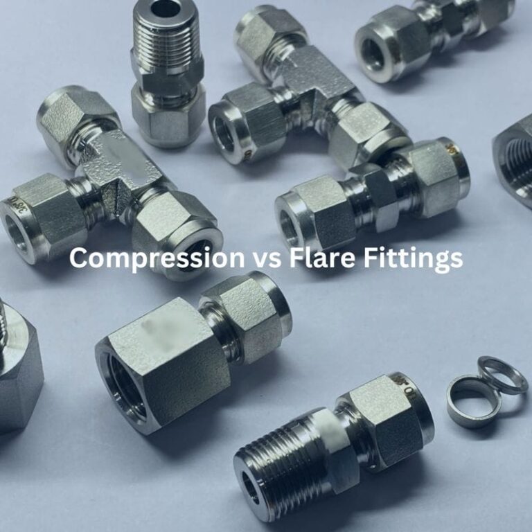
Compression vs Flare Fittings: Choosing the Right One
Table of Contents
Introduction
Making the wrong choice could lead to leaks, system failures, or costly repairs. In this post, we’ll delve into the world of compression and flare fittings, two popular options each with their own set of benefits and applications. Compression fittings offer ease of installation and versatility, while flare fittings excel in high-pressure and vibration-prone environments. Understanding these options and their respective advantages will empower you to make an informed decision, ultimately leading to a more efficient and reliable system.
Understanding Compression Fittings
Compression fittings are a type of fitting used to connect two pipes or a pipe to a fixture or valve. These fittings are commonly used in plumbing and other applications requiring a secure and leak-proof connection. They are especially useful for situations where the pipe cannot be easily welded or soldered.
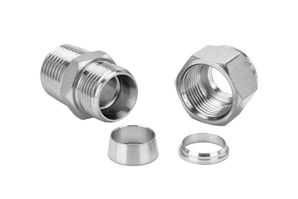
Description of Components
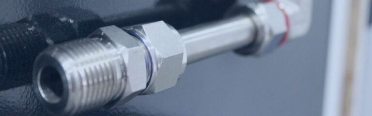
Nut: The nut is the external component that threads onto the fitting body. When tightened, it compresses the ferrule against the pipe and fitting body, creating a secure connection.
Ferrule: The ferrule, often made of brass or plastic, is a small ring that is compressed between the nut and fitting body. It forms a tight seal by deforming and clamping around the pipe as the nut is tightened.
Fitting Body: The fitting body is the main part of the compression fitting that connects to the pipe. It has a seat where the ferrule is compressed, ensuring a leak-proof seal.

How Compression Fittings Create a Seal
When the nut is tightened, it forces the ferrule to deform and compress against the pipe and the internal surface of the fitting body. This deformation creates a tight seal that prevents fluid from leaking out, ensuring a secure connection. The process of compression does not rely on threading into the pipe, making it ideal for softer materials that cannot be threaded.
Materials and Types
Common Materials Used in Compression Fittings
Brass: Brass is widely used due to its durability, resistance to corrosion, and suitability for a wide range of temperatures and pressures.
Copper: Copper compression fittings are commonly used in plumbing for their excellent corrosion resistance and compatibility with copper piping.
Plastic: Plastic fittings, typically made from materials like PVC or PEX, are used for lower-pressure applications and where chemical resistance is necessary.
Different Types of Compression Fittings
Standard Compression Fittings: These are the most common type, used in general plumbing applications for water and gas lines.
High-Pressure Compression Fittings: Designed for applications that require higher pressure tolerance, such as in industrial settings or hydraulic systems. These fittings often have reinforced components to handle the increased stress.
Understanding Flare Fittings
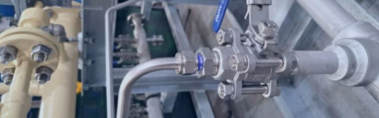
Flare fittings are a type of compression fitting used for high-pressure applications and environments where reliable, leak-proof connections are critical. These fittings are widely used in industries such as automotive, aerospace, refrigeration, and gas lines due to their robustness and ability to handle high stress and vibration.
Description of Components
Flare Nut: The flare nut is a threaded component that is screwed onto the fitting body. It holds the flared end of the tubing in place and compresses it against the fitting body to create a tight seal.
Flared Tubing: The tubing end is flared, or spread outward, at a 45-degree or 37-degree angle to fit snugly against the fitting body. This flaring process is done using a special tool called a flaring tool.
Fitting Body: The fitting body is the main part of the flare fitting that connects to the flared tubing. It has a conical seat where the flared end of the tubing rests, ensuring a secure and leak-proof connection when the flare nut is tightened.
How Flare Fittings Work
When the flare nut is tightened onto the fitting body, it presses the flared end of the tubing against the conical seat inside the fitting body. This action creates a strong, mechanical seal that prevents fluid or gas from leaking. The flared end of the tubing conforms to the shape of the conical seat, providing a large contact area that enhances the sealing capability. This method of sealing is highly effective in high-pressure applications and environments with significant vibration or thermal expansion.
Materials and Types

Common Materials Used in Flare Fittings
Steel: Steel flare fittings are commonly used in applications where strength and durability are paramount. They are well-suited for high-pressure and high-temperature environments.
Brass: Brass is a popular material for flare fittings due to its excellent corrosion resistance and workability. Brass fittings are often used in plumbing, refrigeration, and automotive applications.
Copper: Copper flare fittings are used primarily in refrigeration and air conditioning systems due to copper’s excellent thermal conductivity and corrosion resistance.
Different Types of Flare Fittings
45-Degree Flare Fittings: These fittings are commonly used in refrigeration and air conditioning systems. The 45-degree angle provides a reliable seal for low to moderate-pressure applications.
37-Degree Flare Fittings: Also known as JIC fittings, these are used in hydraulic and high-pressure applications. The 37-degree angle provides a robust seal suitable for high-stress environments.
SAE Flare Fittings: SAE fittings follow specific standards for automotive and hydraulic applications. They typically use a 45-degree flare and are designed to meet stringent performance criteria.
JIC Fittings: JIC fittings use a 37-degree flare and are widely used in the fluid power industry for their reliable sealing and compatibility with high-pressure systems.
Applications of Compression and Flare Fittings
Common Uses of Compression Fittings
Residential Plumbing
Compression fittings are widely used in residential plumbing due to their ease of installation and reliability. They are commonly used for connecting water supply lines to faucets, toilets, and other fixtures. Homeowners and plumbers alike appreciate compression fittings for their ability to create secure connections without the need for soldering or specialized tools.
HVAC Systems
In HVAC (Heating, Ventilation, and Air Conditioning) systems, compression fittings are employed to connect various components, such as copper tubing for refrigerant lines. Their ability to handle moderate pressures and temperatures makes them suitable for these applications. Additionally, the ease of disassembly allows for straightforward maintenance and repairs.
Low to Medium-Pressure Fluid Systems
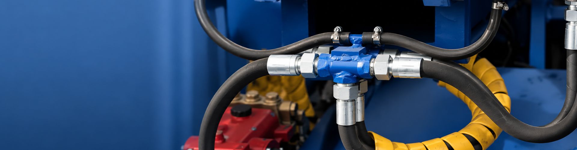
Compression fittings are also used in various industrial applications involving low to medium-pressure fluid systems. This includes chemical processing, water treatment, and hydraulic systems where ease of installation and the ability to quickly disconnect and reconnect lines are essential.
Common Uses of Flare Fittings
High-Pressure Gas and Liquid Systems
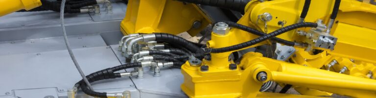
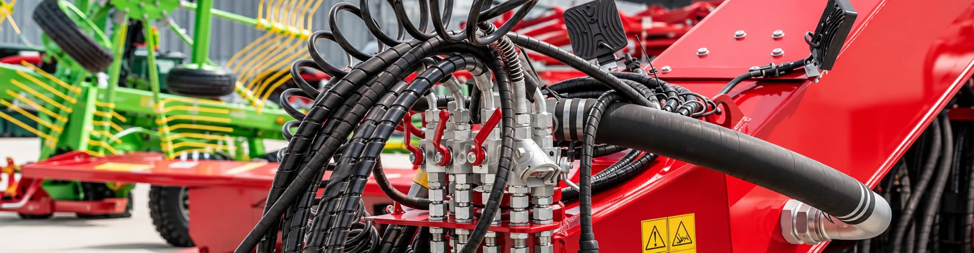
Flare fittings are preferred in high-pressure gas and liquid systems because of their robust sealing capabilities. They are commonly used in natural gas distribution, fuel lines, and hydraulic systems where maintaining a secure, leak-proof connection under high pressure is critical. The mechanical seal created by the flared tubing ensures reliability even under extreme conditions.
Aerospace and Automotive Industries
In the aerospace and automotive industries, flare fittings are crucial for connecting various fluid and gas lines. Their ability to withstand high pressures and resist vibration makes them ideal for applications such as brake lines, fuel systems, and hydraulic lines in aircraft and vehicles. The 37-degree JIC flare fittings, in particular, are standard in these industries due to their compatibility with high-pressure systems.
Refrigeration and Air Conditioning Systems
Flare fittings are extensively used in refrigeration and air conditioning systems. The reliable seal provided by flare fittings ensures that refrigerants do not leak, maintaining system efficiency and performance. Both 45-degree and 37-degree flare fittings are used, depending on the specific requirements of the system.
Industry-Specific Applications
Chemical Processing Industry: In the chemical processing industry, compression fittings are often used for connecting instrumentation and control lines. Their ability to provide leak-proof connections without welding or threading makes them ideal for handling various chemicals safely.
Automotive Industry: The automotive industry relies heavily on flare fittings for fuel and brake lines. The high-pressure requirements and need for vibration resistance make flare fittings the preferred choice. For instance, JIC fittings are standard in many hydraulic systems within vehicles.
HVAC Industry: In HVAC applications, both compression and flare fittings are used. Compression fittings are commonly found in residential installations, while flare fittings are used in commercial and industrial HVAC systems where higher pressures and more rigorous performance standards are needed.
Choosing the Right Fitting for Your Application
Pressure and Temperature Requirements
When selecting between compression and flare fittings, it is crucial to consider the pressure and temperature conditions of your application. Compression fittings are generally suitable for low to medium-pressure systems, making them ideal for residential plumbing and HVAC applications. On the other hand, flare fittings are designed to handle high-pressure environments, such as hydraulic systems, fuel lines, and refrigeration units. Additionally, flare fittings provide excellent performance in both high and low-temperature applications, ensuring a secure connection even under thermal stress.
Environmental Conditions (Vibration, Movement)
The environmental conditions in which the fittings will be used are also a critical factor. Compression fittings are suitable for applications with minimal vibration and movement, as excessive motion can compromise the seal. In contrast, flare fittings are designed to withstand high levels of vibration and movement, making them ideal for automotive, aerospace, and industrial applications where such conditions are common. The robust mechanical seal of flare fittings ensures reliability and longevity in dynamic environments.
Material Compatibility
Material compatibility between the fittings and the pipes or tubing is essential for preventing corrosion and ensuring a long-lasting connection. Compression fittings are available in various materials, including brass, copper, and plastic, each suitable for different applications. For example, brass compression fittings are commonly used in plumbing for their corrosion resistance, while plastic fittings are suitable for low-pressure applications. Flare fittings are typically made from steel, brass, or copper, with each material offering specific advantages. Steel flare fittings provide strength and durability for high-pressure applications, while brass and copper fittings offer excellent corrosion resistance and thermal conductivity for refrigeration and air conditioning systems.
Step-by-Step Guide to Installing Flare Fittings
Tools and Materials Needed
Flaring tool
Tube cutter
Wrenches (appropriate sizes for the flare nut and fitting body)
Deburring tool (optional but recommended)
Flare nut
Tubing (copper, brass, or steel)
Fitting body
Cut the Tubing
Measure and Mark: Measure the length of tubing you need and mark the cutting point.
Cut the Tubing: Use a tube cutter to cut the tubing at the marked point. Ensure the cut is straight and clean.
Deburr the Cut Edge: Use a deburring tool to remove any burrs or rough edges from the cut end of the tubing. This ensures a smooth and clean flare.
Slide the Flare Nut onto the Tubing
Place the Flare Nut: Slide the flare nut onto the tubing, ensuring the threaded end faces the cut end of the tubing. Do this before flaring the tubing to avoid redoing the flare.
Flare the Tubing
Insert the Tubing into the Flaring Tool: Open the flaring tool and insert the cut end of the tubing into the appropriate-sized hole. Ensure the tubing extends slightly beyond the clamp to allow for the flare.
Clamp the Tubing: Tighten the flaring tool clamp to secure the tubing in place. The tubing should be level with the top of the clamp, matching the tool’s guide.
Align the Flaring Cone: Align the flaring cone with the tubing and start turning the flaring tool handle. Apply steady pressure to the handle to form the flare.
Form the Flare: Continue turning the handle until the flare is complete. The tubing should now have a 45-degree or 37-degree flare, depending on the tool and fitting specifications.
Inspect the Flare: Remove the tubing from the flaring tool and inspect the flare for smoothness and evenness. The flare should be uniform and free of cracks or imperfections.
Connect the Tubing to the Fitting Body
Insert the Flared Tubing: Insert the flared end of the tubing into the fitting body. The flared end should sit snugly against the conical seat inside the fitting body.
Thread the Flare Nut: Slide the flare nut up to the fitting body and start threading it onto the fitting by hand. Ensure it threads smoothly to avoid cross-threading.
Tighten the Flare Nut
Tighten by Hand: Initially tighten the flare nut by hand to ensure it is correctly aligned.
Use Wrenches for Final Tightening: Hold the fitting body with one wrench to keep it steady. Use another wrench to tighten the flare nut securely. Do not overtighten, as this could damage the flare or fitting.
Check the Connection: After tightening, inspect the connection to ensure the flare nut is securely fastened and the tubing is properly seated against the fitting body.
Test for Leaks
Pressurize the System: Apply pressure to the system according to the operational specifications.
Check for Leaks: Inspect the flare fitting connection for any signs of leaks. If a leak is detected, depressurize the system and tighten the flare nut further. Repeat the leak test until the connection is leak-free.
Step-by-Step Guide to Installing Compression Fittings
Cut the Tubing
Measure and Mark: Measure the length of tubing needed and mark the cutting point.
Cut the Tubing: Use a pipe cutter to cut the tubing at the marked point. Ensure the cut is straight and clean.
Deburr the Cut Edge: Use a deburring tool to remove any burrs or rough edges from the cut end of the tubing. This ensures a smooth and clean surface for the ferrule to seal against.
Slide the Compression Nut and Ferrule onto the Tubing

Place the Compression Nut: Slide the compression nut onto the tubing with the threaded end facing the cut end.
Add the Ferrule: Slide the Ferrule onto the tubing, placing it between the compression nut and the cut end of the tubing.
Insert the Tubing into the Fitting Body
Insert the Tubing: Push the tubing into the fitting body until it seats firmly against the internal stop inside the fitting body.
Thread the Compression Nut
Hand-Tighten the Nut: Begin threading the compression nut onto the fitting body by hand. Ensure it threads smoothly to avoid cross-threading.
Tighten the Compression Nut
Initial Tightening: Using a wrench, hold the fitting body steady. Use another wrench to tighten the compression nut. Initially, tighten until resistance is felt.
Final Tightening: Tighten the compression nut further, typically one additional full turn past the initial resistance. This compresses the ferrule between the nut and the fitting body, creating a tight seal. Be careful not to overtighten, as this can damage the ferrule or tubing.
Inspect the Connection
Check the Fitting: Inspect the connection to ensure the compression nut is securely fastened and the tubing is properly seated against the fitting body.
Test for Leaks
Pressurize the System: Apply pressure to the system according to the operational specifications.
Check for Leaks: Inspect the compression fitting connection for any signs of leaks. If a leak is detected, depressurize the system and tighten the compression nut slightly further. Repeat the leak test until the connection is leak-free.
Conclusion
In summary, compression and flare fittings each offer distinct advantages and are suitable for different applications. When choosing the right fitting for your application, consider factors such as pressure and temperature requirements, environmental conditions, and material compatibility. We encourage you to carefully assess your specific needs and application requirements before making a decision. By doing so, you can ensure a reliable and efficient fluid or gas system tailored to your needs.
FAQ
Compression fittings are easier to install and are suitable for low to medium-pressure systems. Flare fittings provide a stronger seal for high-pressure and high-vibration environments.
Flare fittings are better suited for high-pressure applications due to their robust sealing capabilities and resistance to vibration.
Yes, compression fittings can be used for gas lines, especially in residential applications. However, ensure they are properly installed and suitable for the specific type of gas.
Yes, flare fittings require a flaring tool to create the flared end of the tubing, ensuring a proper seal with the fitting body.
Compression fittings can be reused, but it is recommended to replace the ferrule each time to ensure a secure seal and prevent leaks.
Compression fittings are typically made from brass, copper, or plastic. Flare fittings are commonly made from steel, brass, or copper, depending on the application’s requirements.


