Proper Assembly of Parallel Thread Adjustable Fittings

Proper Assembly of Parallel Thread Adjustable Fittings

Proper Assembly of Parallel Thread Adjustable Fittings

Table of Contents

Introduction

Parallel thread fittings are essential components in various industrial applications, providing secure connections between hydraulic systems, pipelines, and machinery. These fittings feature parallel threads, which differ from tapered threads by maintaining a consistent diameter along their length, ensuring a tight seal with the help of a sealing washer or O-ring. This guide aims to provide a comprehensive overview of the correct assembly procedures for parallel thread fittings.

Understanding Parallel Thread Fittings

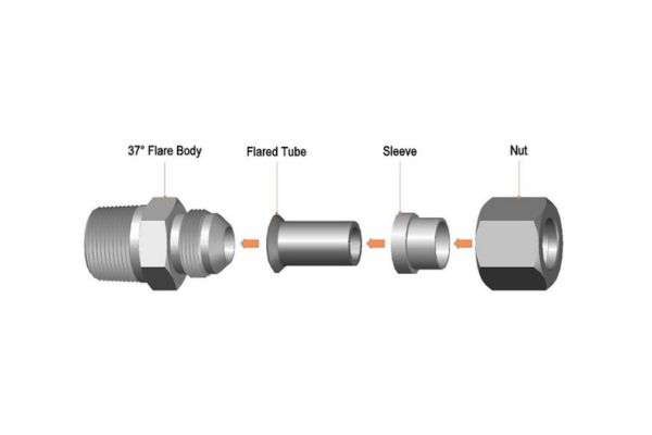
Components and Their Functions

Body:

The body of a parallel thread adjustable fitting is the primary component that connects with other parts of the system. It serves as the structural foundation, housing the threads and adjustment mechanism. The body ensures that the fitting maintains its integrity and provides a stable connection point for the other elements of the system.

Adjustment Mechanism:

The adjustment mechanism within these fittings is crucial for achieving precise alignment and secure connections. This mechanism typically includes a locknut or a similar device, which helps maintain the set position once the fitting is adjusted. The adjustment mechanism allows for fine-tuning, ensuring that the fitting can be positioned accurately within the system.

Threads:

The threads on these fittings are parallel, meaning they maintain a consistent diameter along their length. Unlike tapered threads, parallel threads do not taper but instead rely on a sealing washer or O-ring to achieve a leak-free connection. Key specifications of threads include the thread size, pitch, and profile, which must be compatible with corresponding components to ensure a proper fit and seal.

parallel thread adjustable Fitting

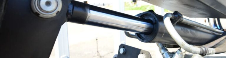
Applications and Benefits

Parallel thread fittings are utilized across a broad spectrum of industries due to their versatility and reliability. Common applications include manufacturing, automotive, aerospace, and various hydraulic and pneumatic systems. These fittings are chosen for their ability to provide secure, leak-free connections, even in high-pressure environments.

Easy Adjustability:

One of the primary benefits of parallel thread fittings is their easy adjustability. The adjustment mechanism allows for precise alignment, making installation and maintenance straightforward. This feature is particularly valuable in complex systems where exact positioning is essential for optimal performance.

Reliable Sealing:

The design of parallel thread fittings ensures a reliable seal, reducing the risk of leaks. This is achieved through the use of sealing washers or O-rings, which compensate for the lack of taper in the threads. The result is a robust, leak-free connection that can withstand varying operational conditions.

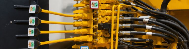
Compatibility with High-Pressure Systems:

These fittings are engineered to perform under high-pressure conditions, making them suitable for demanding applications. Their robust construction and reliable sealing capabilities ensure that they can handle the stresses associated with high-pressure environments without compromising performance.

Types of Parallel Threads

BSPP (British Standard Pipe Parallel)

BSPP threads are one of the most common types of parallel threads used globally, especially in Europe. These threads are characterized by a uniform diameter along their length and a 55-degree thread angle. BSPP threads rely on a bonded seal or an O-ring in a groove to create a leak-tight connection, making them suitable for applications where reliable sealing is crucial, such as hydraulic and pneumatic systems.

UNF (Unified National Fine)

UNF threads are widely used in North America and are part of the Unified Thread Standard. They have a finer pitch compared to UNC (Unified National Coarse) threads, allowing for a greater number of threads per inch. This fine threading provides a stronger and more secure connection, ideal for applications requiring high precision and where space constraints demand a tighter thread fit, such as in automotive and aerospace industries.

ISO Parallel Threads (Metric)

ISO parallel threads, also known as ISO 228-1 or G threads, follow the metric standard and are commonly used worldwide. These threads have a 60-degree thread angle and a consistent diameter, which makes them suitable for a wide range of applications. ISO parallel threads are often found in European and Asian machinery and are preferred for their international standardization, ensuring compatibility across different equipment and components.

Metric standard threads fitting Chart Topa

NPS (National Pipe Straight)

NPS threads are used primarily in the United States and Canada and are similar in design to NPT (National Pipe Tapered) threads but maintain a constant diameter along their length. They are often used in low-pressure applications where the primary sealing method is a gasket or an O-ring rather than the threads themselves. NPS threads are common in plumbing and piping systems where precise alignment is required without the need for thread interference.

SAE Straight Thread

SAE straight threads are designed to provide a reliable, reusable connection in hydraulic and other fluid power systems. These threads are specified by the Society of Automotive Engineers (SAE) and are often used in conjunction with O-rings or other seals to ensure a leak-free connection. The threads themselves provide the mechanical hold, while the seal ensures the system’s integrity under high pressure. This combination is widely used in automotive and industrial applications for its robustness and reliability.

Step-by-Step Assembly Process

Inspection of Components

Checking for Cleanliness:

Before beginning the assembly process, it is crucial to ensure all components are free from dirt, debris, and contaminants. Contaminants can compromise the seal and connection, leading to potential leaks and system failures. Use a clean, lint-free cloth to wipe down each part. For more stubborn debris, consider using a mild solvent that is compatible with the materials of the fittings. Ensuring cleanliness helps maintain the integrity of the assembly and prevents premature wear.

Inspecting Threads for Damage or Wear:

Carefully examine the threads on all components for any signs of wear, deformation, or damage. Even minor imperfections can hinder proper assembly and lead to issues such as cross-threading or inadequate sealing. Use a magnifying glass if necessary to get a detailed view of the thread condition. If you find any damage, replace the affected parts to ensure the assembly process proceeds smoothly and securely.

Aligning the Threads

Importance of Alignment:

Proper thread alignment is essential to prevent cross-threading, which can damage the threads and compromise the seal. Cross-threading occurs when threads are misaligned, causing them to cut across each other rather than mesh smoothly. This not only damages the threads but also affects the fitting’s ability to seal properly.

Techniques for Preventing Cross-threading:

Start threading by hand: Begin the threading process manually to ensure the threads engage smoothly. Hand-threading allows you to feel for any resistance, which could indicate misalignment.

Use light pressure: Apply gentle pressure to guide the threads into place. If you encounter resistance, stop and realign the threads before continuing.

install ferrule fitting

Tightening Components

Recommended Torque Specifications:

Refer to the manufacturer’s guidelines for specific torque values for your fittings. Using the correct torque ensures a secure fit without over-tightening, which can strip the threads or damage the fitting.

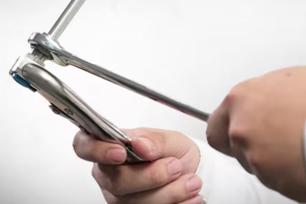
Techniques for Even Tightening:

Apply torque evenly: Distribute the torque evenly across the fitting, using a crisscross pattern if applicable. This helps to prevent uneven stress on the fitting and ensures a secure connection.

Avoid sudden or excessive force: Gradual and steady pressure should be used when tightening. Sudden force can lead to over-tightening or damage to the threads.

Ensuring Proper Sealing

Use of Thread Sealants:

Applying a thread sealant, such as PTFE tape or liquid sealant, is essential for ensuring a leak-free connection. Wrap PTFE tape around the male threads, ensuring even coverage without excess. For liquid sealants, apply a thin, uniform layer to the threads. Sealants fill the gaps between threads, enhancing the seal and preventing leaks.

Checking for Leaks and Verifying the Seal:

Pressurize the system: After assembly, gradually pressurize the system to its operating pressure.

Inspect for leaks: Use soapy water or a leak detection fluid on the connections and watch for bubbles, which indicate leaks. Address any leaks by disassembling and reassembling the fitting with additional sealant if necessary.

Verification and Final Checks

Steps to Ensure the Assembly Is Complete and Correct:

Double-check all connections and fittings: Ensure all parts are properly tightened and aligned.

Confirm proper torque and alignment: Verify that all connections meet the recommended torque specifications and that the threads are correctly aligned.

Tips for Testing the Assembled Fitting:

Conduct a pressure test: Perform a pressure test to ensure the integrity of the seal. This involves pressurizing the system and monitoring for any signs of leakage.

Monitor for signs of leakage or pressure drop: Keep an eye on the system over time to detect any gradual leaks or pressure drops, which could indicate an issue with the assembly.

Common Issues and Troubleshooting

Cross-threading

Cross-threading occurs when the threads on the fittings are misaligned during assembly. This misalignment causes the threads to cut across each other rather than engage smoothly, leading to damage to both the male and female threads. Cross-threading not only makes it difficult to achieve a secure connection but can also result in leaks and compromised system integrity. This issue often arises when excessive force is applied during the initial threading, or when the threads are not started correctly by hand.

Inadequate Sealing

Inadequate sealing is another common problem in the assembly of parallel thread fittings. This issue often stems from insufficient application of thread sealant, incorrect torque application, or using the wrong type of sealant for the specific threads and operating conditions. Inadequate sealing can lead to leaks, which compromise the efficiency and safety of the system. It’s crucial to ensure that the sealant is applied correctly and that the fittings are tightened to the manufacturer’s specified torque values to achieve a proper seal.

Troubleshooting Tips

Identifying and Addressing Common Issues

For Cross-threading:

Disassemble and Inspect Threads: If cross-threading is suspected, immediately stop the assembly process and disassemble the connection. Carefully inspect both the male and female threads for any signs of damage or wear.

Realign Carefully: Clean the threads and realign them carefully. Start the threading process by hand to ensure the threads engage smoothly. If the threads are significantly damaged, consider replacing the affected components to avoid future issues.

For Sealing Issues:

Reapply Thread Sealant: If you encounter sealing issues, disassemble the fitting and remove any old sealant. Clean the threads thoroughly and reapply the appropriate thread sealant. Ensure an even and sufficient application, covering all thread surfaces that will engage.

Ensure Proper Torque: Use a torque wrench to tighten the fittings to the manufacturer’s specified torque values. This ensures a secure fit and proper sealing without over-tightening, which could damage the threads or the seal.

Solutions for Common Problems

Use Thread Gauges to Verify Thread Integrity:

Thread Gauges: Thread gauges are essential tools for verifying the integrity and compatibility of threads. Use them to check the pitch, diameter, and profile of the threads before assembly. This helps ensure that the threads are in good condition and compatible, preventing cross-threading and sealing issues.

Routine Inspections: Regularly inspect and verify thread integrity using thread gauges, especially if fittings are reused or have been stored for an extended period.

Replace Damaged Components as Necessary:

Identifying Damage: If you identify any damage to the threads or fittings during inspection, replace the damaged components immediately. Using compromised parts can lead to repeated assembly issues and potential system failures.

Quality Assurance: Ensure that replacement components meet the required specifications and quality standards. Using high-quality parts reduces the risk of future problems and enhances the overall reliability of the system.

By addressing common issues such as cross-threading and inadequate sealing through careful inspection, proper technique, and the use of appropriate tools and sealants, you can ensure reliable, leak-free connections in your parallel thread adjustable fittings. Consistent attention to detail and adherence to best practices will help maintain the integrity and efficiency of your hydraulic or pneumatic systems.

Conclusion

Proper assembly of parallel thread fittings is critical for system performance and longevity. Key steps include thorough inspection, correct alignment, proper tightening, and effective sealing. By following the outlined procedures and maintaining regular inspections, you can ensure the reliability and efficiency of your fittings, preventing costly downtime and repairs. Follow this guide to achieve optimal results with your parallel thread fittings. Share this post with your peers and explore additional resources or contact us for further assistance.

FAQ

Parallel thread fittings are connectors used in hydraulic and pneumatic systems to join different components. They feature parallel threads, which maintain a consistent diameter and typically use a sealing washer or O-ring to ensure a leak-proof connection.

To prevent cross-threading, always start threading the components by hand to ensure smooth engagement. Use light pressure to guide the threads into place and avoid using excessive force, which can cause misalignment and damage.

The choice of thread sealant depends on the specific application and the type of fluid being used in the system. PTFE tape and liquid thread sealants are common options. Ensure you use a sealant that is compatible with your system’s materials and operating conditions.

After assembly, pressurize the system to its operating pressure and inspect the connections using soapy water or a leak detection fluid. Look for bubbles forming around the fittings, which indicate leaks. Address any leaks by reassembling the fittings with additional sealant if necessary.

Common tools needed for assembly include adjustable wrenches, thread sealant (PTFE tape or liquid), a torque wrench for precise tightening, and inspection tools such as a magnifying glass and thread gauges to check for thread integrity.

Replace your fittings if you notice signs of wear, damage, or deformation during routine inspections. Regularly check for leaks, corrosion, and thread wear. If the fittings are damaged or no longer provide a reliable seal, replace them with new, compatible components to maintain system integrity.

How to Prevent ORFS Braze Sleeve Leaks Top Recommendations

How to Prevent ORFS Braze Sleeve Leaks: Top Recommendations

How to Prevent ORFS Braze Sleeve Leaks: Top Recommendations

Introduction

O-ring face seal braze sleeves are integral components in hydraulic systems, designed to ensure leak-free connections in high-pressure environments. These fittings are widely used across various industries, including construction, agriculture, and manufacturing, due to their superior sealing capabilities and robustness. Leaks in hydraulic systems can lead to significant operational inefficiencies, increased maintenance costs, and potential safety hazards. Therefore, preventing leaks is not only crucial for maintaining system efficiency but also for ensuring the safety and longevity of the hydraulic equipment. This post will delve into the top recommendations for preventing leaks in ORFS braze sleeves, covering essential topics such as proper installation techniques, routine maintenance practices, and troubleshooting tips.

Understanding ORFS Braze Sleeves

O-Ring Face Seal (ORFS) braze sleeves are specialized hydraulic fittings designed to create a secure, leak-proof connection in high-pressure systems. These fittings use an O-ring seated in a groove on the face of the fitting, which is compressed against a flat surface on the opposing fitting to create a tight seal. The braze sleeve itself is typically attached to a tube or hose, forming a durable connection that can withstand high pressures and prevent leaks.

Breakdown of the Key Components

O-Rings:

The O-ring is a crucial component, usually made of elastomeric materials, which provides the primary sealing mechanism by compressing against the flat face of the opposing fitting.

Sleeve:

The sleeve is the part of the fitting that is brazed onto the hydraulic tubing or hose, ensuring a secure and permanent connection.

Face Seal:

The face seal is the flat surface against which the O-ring is compressed, creating the leak-proof seal. This component must be precisely machined to ensure a proper fit and effective sealing.

Prevent ORFS Braze Sleeve Leaks

Applications

Construction Equipment: Used in heavy machinery like excavators and bulldozers where high-pressure hydraulic systems are critical.

Agriculture: Employed in tractors and other farming equipment that rely on hydraulic systems for operation.

Manufacturing: Integral in factory machinery that uses hydraulic systems for automation and production processes.

Automotive: Used in various hydraulic applications within vehicles, such as brake systems and power steering.

Benefits

Leak Prevention:

The primary benefit of ORFS braze sleeves is their ability to create a leak-proof seal, which is essential for maintaining the efficiency and safety of hydraulic systems.

High-Pressure Tolerance:

These fittings are designed to withstand high-pressure environments, making them suitable for demanding applications where standard fittings might fail.

Durability:

The brazed connection provides a strong, durable bond that can endure the stresses of high-pressure hydraulic systems over time.

Ease of Maintenance:

ORFS braze sleeves can be easily inspected and maintained, reducing downtime and maintenance costs.

Versatility:

These fittings can be used in a variety of applications across different industries, providing a versatile solution for hydraulic systems.

Common Causes of ORFS Braze Sleeve Leaks

Improper Installation

Improper installation of ORFS braze sleeves is a significant cause of leaks. Common issues include:

Misalignment of Components: When components are not properly aligned, the seal may not fit correctly, leading to leaks. Misalignment can occur if the components are not properly centered or if there is an angle mismatch, causing uneven pressure distribution and eventual leakage.

Incorrect Assembly Procedures: Deviations from the recommended assembly procedures can also lead to leaks. For instance, if the O-ring is not seated correctly or if the sleeve is not properly positioned, it can prevent the formation of a tight seal. Common assembly mistakes include not following the manufacturer’s torque specifications or using incompatible components.

Examples:

Misaligned Seals: If the sleeve is not aligned with the face seal, the O-ring might not form a complete seal, leading to leakage.

Improper Tool Use: Using the wrong tools during assembly can cause misalignment or damage to the components, resulting in leaks.

O-Ring Damage

Causes and Impact

O-ring damage is another common cause of leaks. Damage can result from:

Chemical Exposure: O-rings are often made from materials that can be sensitive to chemicals. Exposure to harsh chemicals or solvents can degrade the O-ring material, leading to swelling, hardening, or cracking, which impairs its sealing ability.

Physical Damage: During installation or operation, physical damage such as scratches, cuts, or abrasions can occur. Such damage compromises the O-ring’s integrity and its ability to form a reliable seal, leading to potential leaks.

Improper Handling: Mishandling of O-rings during installation, such as twisting, stretching, or using sharp tools, can cause damage. Proper handling and installation practices are crucial to maintaining the O-ring’s effectiveness.

Examples:

Chemical Contamination: Exposure to hydraulic fluids or other chemicals can deteriorate the O-ring, making it prone to leaks.

Installation Errors: Using metal tools to handle the O-ring can cause cuts or nicks, leading to leaks once the system is pressurized.

ORFS braze leak

Incorrect Torque Settings

Importance of Correct Torque

Applying the correct torque is crucial for a proper seal. Incorrect torque settings can lead to:

Over-Torquing: Excessive torque can damage the fitting, O-ring, or other components. Over-torquing can compress the O-ring beyond its designed capacity, leading to deformation and leaks. It can also cause stress fractures in the fitting or the surrounding materials, compromising the connection.

Under-Torquing: Insufficient torque results in a loose connection that can lead to leaks. Under-torquing prevents the O-ring from forming a tight seal against the mating surface, which allows fluids to escape under pressure.

Examples:

Excessive Compression: Over-tightening can crush the O-ring, creating gaps and causing leaks.

Loose Connections: Under-tightened fittings can shift or separate, resulting in fluid leakage.

Wear and Tear

Impact of Wear and Tear

Over time, components in hydraulic systems, including ORFS braze sleeves, undergo wear and tear, leading to:

Degradation of the O-Ring and Sealing Surfaces: Continuous use and exposure to pressure and environmental factors can degrade the O-ring material and sealing surfaces. The O-ring may lose its elasticity and resilience, while sealing surfaces may become worn or damaged.

Increased Risk of Leaks: Worn-out components are less effective at maintaining a secure seal, increasing the likelihood of leaks. As the O-ring and surfaces deteriorate, the integrity of the connection is compromised, leading to potential fluid leakage.

Examples:

Deteriorated O-Ring: An old, worn-out O-ring may no longer provide an adequate seal, resulting in leaks.

Worn Sealing Surfaces: Continuous friction can erode sealing surfaces, causing gaps and leaks.

Contamination

Role of Contaminants

Contaminants can significantly impact the effectiveness of ORFS braze sleeves:

Dirt and Debris: Particles of dirt or debris can interfere with the sealing surfaces, preventing the O-ring from forming a complete seal. Contaminants can also cause abrasive wear on the sealing surfaces, leading to leaks.

Oil and Grease: While some lubrication is necessary, excessive oil or grease can affect the O-ring material, leading to swelling or degradation. Contaminants such as dirt mixed with oil can also create a gritty substance that compromises the seal.

Examples:

Debris Accumulation: Dirt trapped between the O-ring and sealing surface can create gaps and lead to leaks.

Excessive Lubricant: Too much lubricant can cause the O-ring to swell or become slippery, impairing its sealing ability.

Troubleshooting ORFS Braze Sleeve Leaks

Initial Diagnosis

When a Leak is Identified

Isolate the Affected Area:

Shut Down the System: To ensure safety and prevent further damage, turn off the hydraulic system or isolate the section where the leak is occurring.

Drain Fluid if Necessary: Depending on the system, it may be necessary to drain the hydraulic fluid to safely inspect and address the leak.

Conduct a Visual Inspection:

Check for Obvious Issues: Examine the area around the braze sleeve for visible signs of leakage, such as fluid dripping or pooling. Look for any visible damage to the fittings, O-rings, or other components.

Identify Leak Source: Look for tell-tale signs like wet spots or streaks that can help locate the source of the leak.

Examples:

Dripping Fluid: If fluid is dripping from a specific connection, it might indicate a problem at that point.

Discoloration or Staining: Fluid leakage might cause discoloration or staining around the connection, which can help in pinpointing the issue.

Systematic Troubleshooting Process

Follow a Step-by-Step Process to Pinpoint the Exact Cause of the Leak:

Check for Proper Torque:

Verify Torque Settings: Use a torque wrench to ensure that all connections are tightened to the manufacturer’s specifications. Check if any fittings are over-torqued or under-torqued.

Re-torque if Needed: If you find any discrepancies in torque, adjust the fittings to the correct torque settings.

Inspect O-Rings for Damage:

Examine O-Ring Condition: Remove and inspect the O-ring for signs of damage, such as cracks, cuts, or swelling. Check for signs of chemical degradation or physical wear.

Assess O-Ring Seating: Ensure that the O-ring is properly seated in its groove and is not displaced or misaligned.

Verify the Cleanliness of Components:

Inspect Sealing Surfaces: Ensure that the sealing surfaces are clean and free of debris, dirt, or contaminants that might interfere with the seal.

Clean Components if Necessary: Use appropriate cleaning methods to remove any contaminants from the components before reassembly.

Examples:

Improper Torque: If connections are not torqued correctly, this could be a potential cause of leakage.

Damaged O-Ring: A damaged or improperly seated O-ring can compromise the seal and lead to leaks.

Repair and Replacement Procedures

If Faulty Components are Identified:

Replace Damaged O-rings and Sleeves:

Obtain Replacement Parts: Use new O-rings and sleeves that meet the specifications of your system. Ensure that they are of high quality and compatible with your hydraulic components.

Remove and Replace: Carefully remove the damaged components and install the new ones, making sure to follow the correct installation procedures.

Reassemble Following Proper Techniques:

Follow Assembly Guidelines: Reassemble the components according to manufacturer guidelines, ensuring proper alignment and seating of all parts.

Apply Correct Torque: Use a torque wrench to apply the correct torque settings to all connections to ensure a secure and leak-proof assembly.

Test the System to Ensure the Leak is Resolved:

Conduct a Leak Test: Once reassembled, pressurize the system and carefully monitor the area for any signs of leakage. Check all connections and components to ensure that the leak has been fully resolved.

Observe System Operation: Monitor the system under normal operating conditions to ensure that the repair has been successful and no further leaks are present.

Examples:

Replacing O-rings: If the O-ring is damaged, replacing it with a new one and ensuring it is properly seated can fix the leak.

Reassembly and Testing: After reassembly, conducting a thorough leak test helps confirm that the repair was successful and that no further issues are present.

Conclusion

By understanding the key factors that contribute to ORFS braze sleeve leaks—such as improper installation, O-ring damage, incorrect torque settings, wear and tear, and contamination—you are better equipped to tackle and prevent these issues. Regular maintenance, correct assembly procedures, and adherence to manufacturer guidelines further enhance the reliability of your hydraulic system.

FAQ

An ORFS (O-Ring Face Seal) braze sleeve is a hydraulic component designed to create a secure, leak-proof connection between hydraulic hoses and fittings. It features a sleeve with an O-ring that provides a tight seal against the face of the fitting, ensuring reliable performance under high pressure.

Common signs of a leak include visible fluid dripping from the connection, wet spots around the sleeve, or fluid pooling underneath the fitting. You might also notice a decrease in system pressure or performance issues.

The most common causes include improper installation, damaged O-rings, incorrect torque settings, wear and tear, and contamination. Each of these factors can compromise the integrity of the seal and lead to leaks.

To prevent leaks, ensure proper installation and alignment of components, use correct torque settings, regularly inspect and maintain O-rings and sealing surfaces, and keep components clean and free of contaminants. Following manufacturer guidelines and using the right tools is also essential.

If you find a leak, isolate the affected area and conduct a thorough inspection to identify the cause. Check for proper torque, inspect O-rings for damage, and verify the cleanliness of components. Replace any damaged parts, reassemble the connection correctly, and test the system to ensure the leak is resolved.

Regular maintenance should be part of your routine schedule. Perform visual inspections and maintenance checks periodically, depending on your system’s usage and operating conditions. Implementing a regular maintenance routine helps to identify and address potential issues before they lead to leaks.

Proper Assembly of 37° Flare Fittings Using the Flats Method

Proper Assembly of 37° Flare Fittings Using the Flats Method

Proper Assembly of 37° Flare Fittings Using the Flats Method

Introduction

37° flare fittings are crucial components in hydraulic systems, known for their high-pressure tolerance, leak resistance, and reusability. These fittings connect tubes and hoses, ensuring fluid integrity and system reliability. Proper assembly of these fittings is essential to prevent leaks and maintain system performance. The Flats Method is a precise technique used to achieve the correct torque when assembling 37° flare cone fittings. By tightening the fitting to a specific number of flats, this method ensures consistent and reliable connections.

Understanding 37° Flare Cone Fittings

37° fittings, also known as JIC (Joint Industry Council) fittings, are a type of compression fitting used in high-pressure hydraulic systems. These fittings consist of a nut, a sleeve (or ferrule), and a body. The tube end is flared to a 37° angle, which mates with the fitting’s conical seat, creating a tight seal. The main components include:

Nut: Tightens the connection.

Sleeve: Supports the tube and ensures alignment.

Body: Contains the 37° seat and threads.

An and JIC Fittings

Common Applications in Hydraulic Systems

37° flare cone fittings are widely used in various industries due to their robust design and high-pressure capability.

Common applications include:

Automotive: Brake lines and fuel systems.

Industrial Machinery: Hydraulic circuits in heavy equipment.

Marine: Hydraulic systems in ships and boats.

Agriculture: Machinery and equipment requiring durable hydraulic connections.

Advantages

37° flare cone fittings offer several benefits that make them a preferred choice in many hydraulic applications:

High-Pressure Tolerance: These fittings can handle high-pressure environments, making them ideal for demanding hydraulic systems. Their robust construction ensures that they can withstand the stress and pressure without failure.

Leak Resistance: The precise 37° flare angle provides a reliable seal, reducing the risk of leaks. This is crucial for maintaining system integrity and preventing fluid loss, which can lead to inefficiencies and potential hazards.

Reusability: 37° flare cone fittings are designed to be disassembled and reassembled multiple times without losing their sealing capability. This reusability makes them cost-effective and convenient for maintenance and repairs.

Flaring the Tube

Step-by-Step Guide to Flaring the Tube End

Cutting the Tube to the Desired Length

Measure and Mark: Begin by measuring the tube to the required length and marking it with a marker or scribe. Ensure accuracy to avoid cutting too short or too long.

Secure the Tube: Place the tube in a tube cutter, ensuring it is securely positioned. Tighten the cutter just enough to hold the tube without crushing it.

Rotate and Tighten: Rotate the cutter around the tube, gradually tightening the cutter with each rotation until the tube is cut through. Avoid over-tightening, as this can deform the tube.

Deburring the Inside and Outside of the Tube

Deburring Tool Selection: Choose an appropriate deburring tool designed for both the inside and outside of the tube.

Inside Deburring: Insert the deburring tool into the tube end and rotate it to remove any sharp edges or burrs. This step is crucial for preventing damage to the fitting during assembly.

Outside Deburring: Use the deburring tool on the outer edge of the tube to smooth out any rough spots. A clean, smooth edge ensures a better flare and seal.

Using the Flaring Tool to Create the Flare

Select the Flaring Tool: Choose a flaring tool compatible with the tube size and material. Ensure the tool is clean and in good condition.

Insert the Tube: Place the tube into the flaring tool’s clamp. The tube should extend slightly above the clamp to create the flare.

Tighten the Clamp: Secure the tube in place by tightening the clamp. Ensure the tube is centered and aligned correctly.

Create the Flare: Rotate the flaring tool’s handle to press the tube end into the flaring cone. Apply steady pressure to form a 37° flare.

Inspect the Flare: Remove the tube from the tool and inspect the flare. It should be even, smooth, and free of cracks or distortions.

Common Mistakes to Avoid During Flaring

Improper Tube Cutting: Cutting the tube unevenly can result in a poor flare and an unreliable connection. Always use a tube cutter for a clean cut.

Skipping Deburring: Failing to deburr the tube can cause damage to the fitting and compromise the seal. Always deburr both the inside and outside edges.

Incorrect Tool Selection: Using the wrong size or type of flaring tool can result in an improper flare. Ensure the tool matches the tube specifications.

Over-tightening the Clamp: Over-tightening can deform the tube while under-tightening can lead to slippage. Tighten the clamp just enough to hold the tube securely.

Inconsistent Pressure: Applying inconsistent pressure while flaring can lead to an uneven flare. Maintain steady, even pressure throughout the process.

Ensuring a Proper Flare for Optimal Connection

Even and Smooth Flare: A proper flare should be even and smooth, without any cracks, splits, or rough edges. This ensures a tight seal and reliable connection.

Correct Angle: The flare should be precisely at a 37° angle to match the fitting. Use a flaring tool designed for 37° flares to achieve this.

Clean Surface: Ensure the flared surface is clean and free of debris. Any dirt or particles can compromise the seal and lead to leaks.

Proper Alignment: When assembling the fitting, ensure the flare is properly aligned with the fitting’s nose. Misalignment can cause uneven pressure and potential leaks.

Tightening with Flats Method: Use the Flats Method to achieve the correct torque. This involves tightening the fitting to a specific number of flats (e.g., 1.5 or 2 flats) beyond hand-tightening to ensure a consistent and reliable connection.

The Flats Method Explained

Definition and Importance of the Flats Method

The Flats Method is a precise technique used to achieve the correct torque when assembling 37° flare cone fittings. By tightening the fitting by a specific number of flats beyond hand-tightening, this method ensures consistent and reliable connections. The flats refer to the flat sides of the hex nut on the fitting.

The importance of the Flats Method lies in its ability to provide a standardized approach to tightening, reducing the risk of under- or over-tightening. Proper torque is crucial in hydraulic systems to maintain leak-free connections and ensure the longevity of the fittings and tubes.

install 37° Flare Fitting

Step-by-Step Process for Using the Flats Method

Initial Hand-Tightening of Fittings

Position the Tube and Fitting: Align the flared tube end with the fitting nose. Ensure the flare seats are properly against the fitting’s conical surface.

Hand-Tighten the Nut: Begin by threading the nut onto the fitting body by hand. Turn the nut until it is snug and cannot be tightened further by hand. This ensures that the flare is properly seated and aligned.

Marking the Flats of the Fitting

Identify a Flat: Choose one of the flat sides of the hex nut as your starting point.

Mark the Flat: Use a permanent marker or scribe to mark this flat. This mark will serve as a reference point for the subsequent tightening process.

Tightening the Fitting by the Specified Number of Flats

Determine the Required Flats: Consult the manufacturer’s specifications to determine the correct number of flats to tighten beyond hand-tightening. This is typically expressed as a fraction or whole number (e.g., 1.5 flats or 2 flats).

Tighten Using a Wrench: Using a wrench, begin to tighten the nut. Count the flats as you turn the wrench, using your mark as a reference. For example, if the specification calls for 1.5 flats, you will turn the nut until your mark passes the 1.5 flat sides of the hex nut.

Ensure Consistent Pressure: Apply steady, consistent pressure while tightening to avoid any sudden movements that could result in uneven torque.

Benefits of Using the Flats Method Over Other Methods

Precision and Consistency: The Flats Method provides a precise and consistent way to achieve the correct torque, reducing variability that can occur with other methods.

Reduced Risk of Over-Tightening: Over-tightening can damage the fitting and tube, leading to potential leaks and failures. The Flats Method helps prevent this by providing a clear stopping point.

Ease of Use: The method is straightforward to implement, even for those new to assembling hydraulic fittings.

Reliability: By ensuring proper torque, the Flats Method enhances the reliability of the connection, contributing to the overall performance and safety of the hydraulic system.

Standardization: This method allows for standardization across different assemblies, making it easier to train personnel and maintain consistency in assembly processes.

Assembling the 37° Flare Cone Fittings

Positioning the Flare Against the Fitting Nose

Preparation: Begin by ensuring the tube is properly flared and deburred. The flare should be smooth and even, with no cracks or distortions.

Align the Tube: Position the flared tube end against the fitting nose. Make sure the flare sits perfectly on the conical seat of the fitting. This alignment is crucial for a proper seal.

Hold in Place: Hold the tube and fitting in place, ensuring they are aligned and the flare is seated correctly on the fitting nose.

Hand-Tightening the Fitting

Start Threading: Begin by threading the nut onto the fitting body by hand. This initial hand-tightening ensures that the threads engage correctly and the flare remains seated.

Snug Fit: Continue to turn the nut by hand until it is snug and cannot be tightened further without tools. This hand-tightening step is essential to maintain the alignment and ensure the flare is properly seated.

install ferrule fitting

Using the Flats Method to Achieve Proper Torque

Mark the Flats: Identify one of the flat sides of the hex nut and mark it with a permanent marker or scribe. This mark will help you track the number of flats turned during tightening.

Determine Flats to Tighten: Refer to the manufacturer’s specifications to determine the number of flats required for proper torque. This is usually indicated in the fitting’s assembly instructions.

Tighten the Nut: Using a wrench, begin to tighten the nut. Turn the nut by the specified number of flats (e.g., 1.5 flats or 2 flats) beyond the initial hand-tightened position. Use your mark as a reference point to ensure accuracy.

Apply Steady Pressure: Maintain steady, even pressure while turning the wrench to avoid any sudden movements that could cause uneven torque or damage the fitting.

Checking for Proper Alignment and Fit

Inspect the Connection: After tightening the nut using the Flats Method, inspect the connection to ensure the flare is properly seated and aligned with the fitting nose.

Check for Gaps: Look for any gaps between the flare and the fitting nose. There should be no visible gaps, as this could indicate misalignment or improper seating.

Verify Tightness: Ensure the nut is tightened to the specified torque by checking the number of flats turned. If necessary, adjust slightly to achieve the correct torque.

Tips for Ensuring a Leak-Free Connection

Proper Preparation: Always start with properly cut, deburred, and flared tubes. This preparation is critical for a good seal.

Use Quality Fittings: Ensure that you use high-quality fittings that match the specifications of your hydraulic system. Inferior fittings can lead to leaks and system failures.

Avoid Over-Tightening: Over-tightening can damage the fitting and the flare, leading to leaks. The Flats Method helps prevent this by providing a clear and standardized approach to tightening.

Regular Inspection: Periodically inspect the fittings for signs of wear, corrosion, or damage. Early detection of issues can prevent leaks and extend the life of your hydraulic system.

Consistent Maintenance: Follow a regular maintenance schedule to check the condition of all fittings and connections. This proactive approach ensures long-term reliability and performance.

Troubleshooting and Common Issues

Identifying and Fixing Leaks

Check for Fluid: Look for visible signs of fluid around the fitting. Leaks often present as wet spots or drips.

Tighten the Nut: If a leak is detected, attempt to tighten the fitting slightly more, following the Flats Method guidelines.

Replace Damaged Components: If tightening doesn’t resolve the leak, inspect the flare and fitting for damage and replace as necessary.

Inspecting the Flare and Fitting Surfaces

Visual Inspection: Examine the flare for cracks, irregularities, or deformation.

Surface Cleanliness: Ensure the fitting surfaces are clean and free of debris that could affect the seal.

Correcting Misalignment

Reposition the Tube: If the flare isn’t seated properly, loosen the fitting and reposition the tube to ensure proper alignment.

Re-tighten Carefully: Hand-tighten again, followed by the Flats Method to achieve the correct torque.

Addressing Under- or Over-Tightening

Under-Tightening: Identify by feeling a loose connection. Tighten the fitting to the correct specification using the Flats Method.

Over-Tightening: Look for signs such as distorted flares or cracked fittings. If over-tightened, replace the damaged components and reassemble correctly.

Preventing Damage to Fittings and Tubes

Use Proper Tools: Always use the right size wrench to avoid rounding off the nut or damaging the tube.

Follow Specifications: Adhere to manufacturer guidelines for torque and the number of flats to ensure consistent and damage-free assembly.

Regular Maintenance: Periodically inspect fittings for signs of wear or corrosion, replacing parts as needed to maintain system integrity.

Conclusion

Proper assembly of 37° flare fittings is crucial for ensuring leak-free and reliable hydraulic connections. By following the Flats Method, you achieve precise and consistent torque, which enhances the durability and performance of your system. This method standardizes the assembly process, reducing the risk of under- or over-tightening, and helps in maintaining optimal system integrity. We encourage you to adhere to the best practices outlined in this guide, including regular inspections and maintenance, to prolong the life of your fittings and tubes.

FAQ

37° flare cone fittings, also known as JIC fittings, are used in high-pressure hydraulic systems to connect tubes and hoses securely.

The Flats Method is a technique for tightening fittings by a specific number of flats beyond hand-tightening to ensure proper torque and a reliable seal.

Proper assembly prevents leaks, ensures system integrity, and extends the lifespan of hydraulic components.

Hand-tighten the fitting, mark one flat side, then tighten by the specified number of flats using a wrench.

Inspect the fitting and flare for damage, ensure proper alignment, and re-tighten or replace components as necessary.

Regular inspections should be conducted periodically to check for signs of wear, corrosion, or loosening to maintain system performance.

Preventing Leaks in Hydraulic Ports Expert Tips

Preventing Leaks in Hydraulic Ports: Expert Tips

Preventing Leaks in Hydraulic Ports: Expert Tips

Table of Contents

Introduction

Hydraulic systems are essential to many industries, from manufacturing and construction to automotive and aerospace. However, one of the most common and detrimental issues these systems face is leakage. Preventing leaks in ports is crucial for maintaining optimal system performance and ensuring safety. Hydraulic leaks can significantly degrade the efficiency of a system, leading to reduced power output, increased operational costs, and potential environmental hazards. Undetected leaks, in particular, can escalate into major failures, resulting in costly repairs and downtime. This article aims to provide a comprehensive guide on preventing leaks in ports by exploring various types, identifying common issues, and offering expert tips for effective leak prevention.

Understanding Hydraulic Ports

Ports are critical components in hydraulic systems, serving as connection points where hydraulic lines, fittings, and components join. Understanding the different types of ports and the common issues that can lead to leaks is essential for maintaining system integrity and performance.

Types of Ports

SAE J1926 Ports

SAE J1926 ports are a standard type of hydraulic port widely used in North America. These ports are designed with straight threads and an O-ring seal. The straight threads serve primarily to hold the fitting in place, while the O-ring provides the actual seal. This design allows for easy assembly and disassembly, making maintenance more straightforward.

ISO 6149 Ports

ISO 6149 ports are another common type of hydraulic port, primarily used in European applications. Like the SAE J1926, ISO 6149 ports also utilize straight threads and an O-ring seal. However, these ports are designed to meet international standards that may differ slightly from the SAE specifications. ISO 6149 ports are known for their precision and compatibility with global hydraulic systems, making them a preferred choice for multinational operations.

Differences and Similarities

While both SAE J1926 and ISO 6149 ports utilize straight threads and O-ring seals, there are key differences between the two. One primary difference lies in the dimensional standards and specifications. SAE J1926 ports adhere to the standards set by the Society of Automotive Engineers (SAE), whereas ISO 6149 ports follow the International Organization for Standardization (ISO) guidelines. These differences can affect the interchangeability of components and the specific applications for which each port type is best suited.

However, both port types share similarities in their fundamental design principles. The use of straight threads and O-ring seals in both types ensures a reliable and effective seal, minimizing the risk of leaks when properly assembled. Understanding these nuances helps in selecting the appropriate port type for a given application, ensuring compatibility and optimal performance.

Common Issues Leading to Leaks

Hydraulic port leaks can stem from various issues, often related to manufacturing, installation, and wear over time. Identifying and addressing these common issues is crucial for maintaining a leak-free system.

Manufacturing Defects

Manufacturing defects are a common cause of leaks in ports. These defects can include improperly machined threads, surface imperfections, and dimensional inaccuracies. Even minor defects can prevent the O-ring from seating correctly, leading to leaks. Quality control during the manufacturing process is essential to minimize the occurrence of such defects. Using components from reputable manufacturers who adhere to strict quality standards can help reduce the risk of leaks caused by manufacturing issues.

Leaks in Hydraulic Ports

Improper Installation

Improper installation is another significant contributor to hydraulic leaks. This can involve several factors, including incorrect torque application, misalignment of fittings, and failure to properly seat the O-ring. Over-tightening fittings can damage the threads and O-ring while under-tightening can result in insufficient sealing pressure. Proper training and adherence to installation guidelines are critical to ensure that fittings are installed correctly. Using the correct tools, such as calibrated torque wrenches, can also help achieve the proper installation and prevent leaks.

Wear and Tear Over Time

Wear and tear over time is an inevitable aspect of hydraulic systems. As components are subjected to constant pressure cycles, temperature fluctuations, and mechanical stress, they can degrade and wear out. O-rings can become brittle or damaged, threads can wear down, and seals can lose their effectiveness. Regular maintenance and inspection are essential to identify signs of wear and replace worn components before they lead to leaks. Implementing a proactive maintenance schedule can extend the lifespan of hydraulic systems and reduce the risk of unexpected leaks.

Understanding the types of ports and the common issues that can lead to leaks provides a solid foundation for maintaining a reliable hydraulic system. By addressing these factors through proper inspection, assembly, and maintenance practices, you can significantly reduce the risk of hydraulic leaks and ensure the long-term performance of your system.

Key Preventive Measures

Preventing leaks in ports requires a multifaceted approach that includes proper inspection techniques, correct assembly practices, and the selection of high-quality components. By focusing on these key preventive measures, you can enhance the reliability and efficiency of your hydraulic system.

Proper Inspection Techniques

Initial Inspection of Ports Before Use

Before incorporating any new port into your hydraulic system, it is essential to conduct a thorough initial inspection. This inspection should include checking for any visible defects, such as scratches, burrs, or other irregularities that could compromise the seal. Ensuring that the port is in perfect condition before use can prevent leaks from occurring right from the start.

Regular Maintenance Inspections

Regular maintenance inspections are crucial for identifying potential issues before they escalate into significant problems. These inspections should be scheduled at regular intervals, depending on the system’s usage and operating conditions. During maintenance checks, it is vital to inspect the condition of the ports, fittings, and seals to ensure they are still functioning correctly and have not developed any wear or damage.

Tools and Equipment for Effective Inspection

Using the right tools and equipment is essential for conducting effective inspections. Micrometers, calipers, and borescopes can help identify minute defects that might not be visible to the naked eye. Additionally, using dye penetrant or other non-destructive testing methods can reveal hidden cracks or imperfections. Investing in high-quality inspection tools can significantly improve the accuracy and effectiveness of your inspections.

Correct Assembly Practices

Importance of Torque Specifications

One of the most critical factors in preventing hydraulic leaks is adhering to the correct torque specifications during assembly. Over-tightening or under-tightening fittings can lead to improper sealing and eventual leaks. Always refer to the manufacturer’s torque specifications for each component and use a calibrated torque wrench to ensure accuracy.

Step-by-Step Guide to Assembling O-Ring Boss Fittings

Assembling O-ring boss fittings correctly is vital for achieving a leak-free seal. Begin by ensuring that the O-ring is in good condition and free from defects. Apply a suitable lubricant to the O-ring to reduce friction and prevent damage during assembly. Insert the fitting into the port, and hand-tighten it until the O-ring makes contact with the sealing surface. Use a torque wrench to tighten the fitting to the specified torque value, ensuring that it is neither too loose nor too tight.

Checking for Proper Seating and Alignment

Proper seating and alignment of fittings are crucial for preventing leaks. After tightening the fitting, check that it is correctly seated against the face of the port. There should be no gaps between the fitting and the port surface. Misalignment can cause uneven pressure on the seal, leading to leaks. If necessary, adjust the fitting to achieve proper alignment and seating.

Preventing Leaks in Hydraulic Port

Choosing the Right Components

Selecting High-Quality Fittings and O-rings

Choosing high-quality fittings and O-rings is essential for maintaining a leak-free hydraulic system. Look for components from reputable manufacturers that meet industry standards. High-quality fittings and O-rings are less likely to have manufacturing defects and are more durable, reducing the likelihood of leaks.

Compatibility Considerations Between Components

Compatibility between components is another critical factor in preventing leaks. Ensure that the fittings, ports, and O-rings are designed to work together. Mismatched components can lead to poor sealing and increased wear, resulting in leaks. Always verify compatibility before assembly.

Impact of Material Selection on Leak Prevention

The material selection of fittings and seals can significantly impact leak prevention. Materials should be chosen based on their compatibility with the hydraulic fluid, operating temperature, and pressure conditions. For example, certain elastomers used in O-rings may degrade when exposed to specific hydraulic fluids or high temperatures. Selecting materials that are resistant to these conditions will enhance the longevity and reliability of the seals, reducing the risk of leaks.

Detailed Troubleshooting Guide

Preventing leaks in ports requires a thorough troubleshooting process to identify and address potential issues. This detailed guide covers the essential steps for diagnosing and resolving leaks in hydraulic systems.

Initial Troubleshooting Steps

Depressurizing and Locking Out the System

Before beginning any troubleshooting, it is crucial to ensure the hydraulic system is depressurized and locked out. This step is vital for safety, preventing accidental fluid discharge or system activation during inspection and repair. Follow the manufacturer’s guidelines for safely depressurizing and locking out the system.

Visual Inspection for Obvious Signs of Damage

Once the system is safe to work on, perform a visual inspection of the ports and fittings. Look for obvious signs of damage such as cracks, dents, or corrosion. Inspect the O-rings for signs of wear, brittleness, or cuts. This initial inspection can help identify any glaring issues that might be causing leaks.

Inspecting Internal Threads

Checking for Damage or Wear in Female Ports

Internal threads, also known as female ports, are critical for creating a secure and leak-free connection. Check the threads for signs of damage or wear. Worn threads can prevent the fitting from seating properly, leading to leaks. Use a thread gauge to ensure the threads are within specification and have not been damaged by over-tightening or cross-threading.

Evaluating the O-Ring Sealing Surface

The O-ring sealing surface inside the port should be smooth and free of imperfections. This surface, typically counterbored or chamfered, must be inspected closely for scratches or other damage. Concentric scratches may not pose a problem, but perpendicular scratches can create leak paths by preventing the O-ring from forming a proper seal.

Identifying and Addressing Scratches and Sharp Edges

Sharp edges at the leading edge of the counterbore can damage the O-ring during installation. If sharp edges or significant scratches are found, they should be smoothed out using appropriate tools. Lubricating the O-ring and the sealing surface can also help prevent damage during assembly.

Assessing Assembly Quality

Verifying Torque and Proper Seating of Fittings

Proper torque application is essential to prevent leaks. Use a calibrated torque wrench to ensure that fittings are tightened to the manufacturer’s specifications. Over-tightening can damage threads and O-rings, while under-tightening can result in insufficient sealing pressure. After applying the correct torque, check that the fitting is seated properly against the face of the port. There should be no gaps between the fitting and the port surface.

Identifying Potential Assembly Errors

Common assembly errors that can lead to leaks include misalignment of fittings, incorrect O-ring placement, and failure to use the appropriate lubricant. During inspection, ensure that the fittings are aligned correctly and that the O-rings are seated properly in their grooves. Lubricants should be used where recommended to facilitate proper assembly and prevent O-ring damage.

Steps to Correct Improper Assembly

If improper assembly is identified, take the following steps to correct it:

Disassemble the Components: Carefully remove the fitting and inspect both the port and the fitting for damage.

Clean the Components: Ensure that all components are clean and free from debris that could interfere with sealing.

Reinstall the O-Ring: Place the O-ring in its groove, applying a suitable lubricant is recommended.

Align the Fitting: Align the fitting with the port, ensuring it is straight and not cross-threaded.

Apply Proper Torque: Use a calibrated torque wrench to tighten the fitting to the specified torque value.

Verify Seating: Check that the fitting is properly seated against the port with no gaps.

Common Problems and Solutions

Effectively preventing and troubleshooting leaks in ports involves understanding and addressing common problems. These problems can stem from manufacturing defects, assembly errors, and issues related to material and component selection. This section provides an overview of these common issues and offers practical solutions.

Manufacturing Defects

Recognizing Signs of Defective Ports

Manufacturing defects can manifest in various ways, including improper threading, surface imperfections, and dimensional inaccuracies. Signs of defective ports include:

Misaligned Threads: Threads that do not match the standard profile or are uneven.

Surface Imperfections: Scratches, burrs, or pits on the sealing surfaces.

Dimensional Errors: Ports that do not conform to specified dimensions, causing misfits with standard fittings.

To recognize these defects, use precise measuring tools such as thread gauges, micrometers, and borescopes. Visual inspection under adequate lighting is also crucial.

Handling Different Types of Fluids

How to Address and Rectify Manufacturing Issues

Addressing manufacturing defects involves several steps:

Quality Control: Implement rigorous quality control measures during manufacturing to catch defects early. This includes random sampling and detailed inspections.

Supplier Collaboration: Work closely with suppliers to ensure they understand the importance of quality standards and are committed to meeting them.

Component Replacement: If defects are identified, replace the defective ports with high-quality components from reliable suppliers.

Repair Techniques: Minor surface imperfections can sometimes be repaired using precision machining or polishing techniques.

Hydraulic Ports leak

Assembly Errors

Common Mistakes During Installation

Assembly errors are a leading cause of hydraulic port leaks. Common mistakes include:

Over-Tightening: Applying excessive torque can damage threads and O-rings.

Under-Tightening: Insufficient torque can result in inadequate sealing pressure.

Misalignment: Incorrect alignment of fittings can lead to improper seating and leaks.

Improper O-Ring Installation: Failing to properly seat the O-ring or using a damaged O-ring.

Tips for Avoiding These Errors

To avoid assembly errors:

Follow Manufacturer Guidelines: Always refer to the manufacturer’s torque specifications and installation procedures.

Use the Right Tools: Employ calibrated torque wrenches and alignment tools to ensure accurate assembly.

Training and Certification: Ensure that personnel are well-trained and, if possible, certified in hydraulic assembly practices.

Lubrication: Apply appropriate lubricants to O-rings and threads to facilitate proper installation and prevent damage.

Solutions for Correcting Improper Assembly

If improper assembly is detected, take the following corrective actions:

Disassemble and Inspect: Carefully disassemble the components and inspect for damage.

Replace Damaged Parts: If any parts are damaged, replace them with new ones.

Reassemble with Correct Torque: Reassemble the components using the correct torque and alignment procedures.

Check Sealing Surfaces: Ensure that all sealing surfaces are clean and free from defects before reassembly.

Material and Component Issues

Problems Arising from Incompatible Materials

Using incompatible materials can lead to several problems, including:

Chemical Incompatibility: Certain hydraulic fluids can react with O-ring materials, causing degradation.

Temperature Sensitivity: Materials that are not suitable for the operating temperature range can fail prematurely.

Mechanical Mismatch: Components made from incompatible materials can have differing expansion rates, leading to leaks under temperature fluctuations.

How to Select the Right Materials for Your System

Selecting the right materials involves:

Compatibility Checks: Ensure that all components are compatible with the hydraulic fluid and operating conditions.

Material Specifications: Refer to material specifications and industry standards to select appropriate materials for O-rings, seals, and fittings.

Consulting Experts: Seek advice from material science experts or hydraulic system specialists to make informed choices.

Conclusion

Throughout this guide, we have discussed various preventive measures such as meticulous initial inspections, regular maintenance checks, adherence to torque specifications, and selecting the right materials for your system. Continuous improvement and vigilance are crucial in maintaining a leak-free hydraulic system, as even minor oversights can lead to significant issues over time. As we wrap up, we encourage you to implement the tips and strategies discussed in this guide. By doing so, you can significantly reduce the risk of leaks and ensure the long-term performance of your hydraulic systems.

FAQ

The most common cause of hydraulic port leaks is improper assembly, such as incorrect torque application or misalignment of fittings.

Look for signs such as misaligned threads, surface imperfections, and dimensional inaccuracies. Using precise measuring tools and conducting a thorough visual inspection can help identify these defects.

If the scratch is perpendicular and deep, it can cause leaks. The best solution is to replace the port. For minor scratches, you might be able to smooth them out using precision tools.

Regular maintenance inspections should be conducted based on the system’s usage and operating conditions. Typically, a quarterly inspection is recommended for most hydraulic systems.

Choose O-ring materials compatible with your hydraulic fluid and operating temperature. Common materials include nitrile, fluorocarbon (Viton), and ethylene propylene (EPDM).

Using a torque wrench ensures that fittings are tightened to the manufacturer’s specified torque value, preventing over-tightening or under-tightening, which can lead to leaks.

Hydraulic Fittings Leaking Top Troubleshooting Tips to Know

Hydraulic Fittings Leaking? Top Troubleshooting Tips to Know

Hydraulic Fittings Leaking? Top Troubleshooting Tips to Know

Table of Contents

Introduction

Even the smallest leaks can lead to a significant reduction in system efficiency, potential safety hazards, and costly downtime. Hydraulic fluid leaks can also contribute to environmental contamination, further exacerbating the financial and operational impact. By understanding the root causes of hydraulic fitting leaks, recognizing early symptoms, and employing reliable troubleshooting techniques, operators can maintain system integrity, improve safety, and minimize the costs associated with leaks. This guide provides an in-depth look at these areas, offering practical solutions and preventative measures to ensure the longevity and reliability of hydraulic systems.

Understanding Hydraulic Fittings Leaking

Common Causes of Leaks

Improper Installation

Hydraulic fittings require precise installation techniques to ensure a proper seal and optimal performance. Improper installation is a prevalent cause of leaks, often resulting from incorrect fitting procedures. For instance, over-tightening fittings can damage the threads and deform the sealing surfaces, making it difficult for the fittings to create a secure seal. This deformation can lead to small gaps where hydraulic fluid can escape, resulting in leaks. On the other hand, under-tightening fittings can prevent a proper seal from forming in the first place, allowing fluid to leak out. Both over-tightening and under-tightening can compromise the integrity of the hydraulic system, highlighting the importance of following manufacturer specifications and using the correct torque settings during installation.

Compression Fitting Leaking rust

Damaged Components

Hydraulic systems rely on various components such as fittings, O-rings, and seals to maintain a leak-free environment. Over time, these components can suffer from wear and tear, cracks, or other forms of damage due to the high pressures and harsh operating conditions they are subjected to. Even minor imperfections, such as small cracks or abrasions, can compromise the seal, leading to fluid leaks. For example, a cracked O-ring or a damaged fitting thread can create pathways for fluid to escape, undermining the system’s efficiency. Proactively addressing wear and tear can prevent leaks and extend the lifespan of the hydraulic system.

Contamination

Dirt, debris, and other contaminants can infiltrate hydraulic systems, particularly during assembly or maintenance. These contaminants can obstruct the sealing surfaces or become embedded in the fittings, preventing proper sealing and resulting in leaks. For example, a small particle of dirt trapped between a fitting and its corresponding seal can create a tiny gap, allowing fluid to leak out. Contamination can also accelerate wear and tear on components, further increasing the risk of leaks. Maintaining cleanliness throughout the assembly and maintenance processes, and implementing contamination control practices, such as using clean tools and protective covers, are essential to preventing this common issue. Ensuring that all components are clean and free of contaminants can help maintain the integrity of the seals and prevent leaks.

Wear and Tear

Hydraulic systems are subject to high pressures and repetitive movements, which can cause gradual deterioration of components over time. Continuous exposure to extreme conditions can lead to the hardening, cracking, or wearing out of seals, and the loosening or corrosion of fittings. For example, seals may harden and lose their elasticity, preventing them from forming a tight seal, or fittings may corrode, creating rough surfaces that are prone to leaks. Regularly scheduled maintenance is necessary to mitigate the effects of wear and tear. This includes inspecting components for signs of deterioration and replacing worn parts before they fail. Timely replacement of worn components can prevent leaks, ensuring the hydraulic system remains efficient and reliable. By addressing wear and tear proactively, operators can avoid costly downtime and maintain optimal system performance.

Types of Leaks

External Leaks

External leaks are the most apparent and detectable type of hydraulic leaks, characterized by hydraulic fluid escaping from the system and becoming visible on the exterior. These leaks can often be identified by obvious signs such as pooling fluid beneath machinery, wet spots around fittings, or dripping fluid. The presence of external leaks is a clear indicator that the hydraulic system’s integrity has been compromised, and they require immediate attention. Left unaddressed, external leaks can lead to further system degradation, pose safety hazards, such as creating slippery surfaces that can cause accidents, and result in significant fluid loss. To mitigate these risks, it is crucial to conduct regular visual inspections of the hydraulic system, focusing on areas around fittings, joints, and connections where leaks are most likely to occur. Promptly addressing external leaks by tightening connections, replacing damaged components, or resealing joints can help maintain system performance and safety.

Internal Leaks

leaking hydraulic Fittings Topa

Internal leaks, while not visible externally, can have a profound impact on the performance of a hydraulic system. These leaks occur when hydraulic fluid bypasses internal seals or components within the system, resulting in fluid escaping from the designated flow paths. Unlike external leaks, internal leaks do not leave visible traces, making them more challenging to detect. However, they manifest through various symptoms such as decreased system pressure, slower operational speeds, and reduced overall efficiency. These symptoms occur because the leaked fluid cannot contribute to the system’s power output, leading to a loss of hydraulic power. Detecting internal leaks often requires specialized diagnostic tools and techniques. For example, pressure testing can help identify drops in pressure that indicate internal leaks, and flow meters can measure the rate of fluid movement to detect inconsistencies. Additionally, advanced methods such as thermal imaging can identify temperature changes associated with fluid bypassing within the system. Addressing internal leaks typically involves inspecting and replacing worn or damaged seals, ensuring proper alignment of components, and maintaining the cleanliness of the hydraulic fluid to prevent contamination-related leaks.

Symptoms of Hydraulic Fitting Leaks

Visible Fluid Drips

One of the most apparent and immediate signs of a hydraulic fitting leak is the presence of fluid drips or puddles under machinery or around fittings. These visible signs indicate that hydraulic fluid is escaping from the system, suggesting a breach in the fitting’s integrity. Such leaks can be identified by regular visual inspections of the equipment. Fluid accumulation on the floor or wet spots on and around hydraulic components are telltale indicators. Addressing these visible leaks promptly is crucial to prevent further fluid loss, which can lead to more extensive system damage, operational inefficiencies, and safety hazards. Ignoring visible fluid drips can also result in increased maintenance costs and potential environmental issues due to the spilled hydraulic fluid.

Decreased System Efficiency

Leaks in hydraulic systems often lead to a significant drop in system pressure, resulting in slower operation and reduced overall performance. When hydraulic machinery is not performing as expected—such as experiencing slower cycle times, reduced lifting capacity, or less responsive controls—it may indicate that fluid is leaking either internally or externally. This leakage prevents the system from maintaining the necessary pressure levels required for optimal operation. Operators should monitor the system’s performance indicators and pressure readings regularly. Any unexplained decrease in efficiency or performance should prompt an inspection for potential leaks. Identifying and repairing leaks early can restore system efficiency and prevent further degradation of hydraulic performance.

Noise and Vibration

Unusual noises, such as hissing, whistling, or increased vibration, can also be strong indicators of hydraulic leaks. These symptoms often suggest that air is entering the system or that hydraulic fluid is escaping under pressure. When air enters a hydraulic system, it can cause cavitation—creating pockets of air that collapse under pressure and produce loud, disruptive noises. Additionally, fluid escaping under pressure can create a whistling or hissing sound as it passes through small gaps or cracks in the fittings. Increased vibration can occur when the smooth operation of hydraulic components is disrupted by fluctuating pressure levels or fluid flow. Identifying and rectifying these noises and vibrations can help diagnose and fix leaks. Operators should listen for any changes in the usual sounds of their machinery and feel for unusual vibrations during operation.

Troubleshooting Tips

Initial Assessment

Visual Inspection: Begin by conducting a thorough visual inspection of the hydraulic system. Look for visible signs of fluid drips, pooling fluid, or wet areas around fittings, hoses, and other components. This can help quickly identify the presence of external leaks. Additionally, check for any obvious signs of damage, such as cracked or corroded fittings, which could be the source of the leak.

Identify the Type and Source of the Leak: Once a leak is detected, determine whether it is external or internal. External leaks are typically easier to spot due to visible fluid, while internal leaks may manifest through symptoms like decreased system performance or unusual noises. Identifying the exact location and nature of the leak is crucial for effective troubleshooting and repair.

Detailed Examination

Checking for Damaged Components: Inspect critical components such as O-rings, seals, and threads for signs of wear, cracks, or damage. Damaged O-rings or seals can fail to create a proper seal, leading to leaks. Similarly, worn or damaged threads on fittings can prevent secure connections, allowing fluid to escape.

Ensuring Proper Alignment and Fitment: Verify that all fittings are correctly aligned and securely fitted. Misalignment can cause improper sealing and result in leaks. Ensure that fittings are properly seated and that there are no gaps or misalignments that could compromise the seal.

Inspecting for Contamination and Cleanliness Issues: Ensure that all components are clean and free from debris. Contaminants such as dirt, dust, or metal particles can obstruct sealing surfaces or become embedded in fittings, leading to leaks. Maintaining a clean working environment and using clean tools and materials during assembly can help prevent contamination-related leaks.

Correct Installation Practices

Proper Torque Specifications: Follow the manufacturer’s guidelines for tightening fittings to the correct torque specifications. Over-tightening can damage threads and deform seals, while under-tightening can result in a loose connection that leaks. Using a calibrated torque wrench can help achieve the proper torque.

Using the Right Tools and Techniques: Employ appropriate tools and techniques to avoid damaging components during installation. For example, using the correct size wrenches and avoiding the use of excessive force can prevent damage to fittings and threads. Specialized tools designed for hydraulic systems can help ensure proper installation without causing damage.

Ensuring Alignment and Avoiding Over-Tightening: Properly align fittings during installation to ensure a secure and effective seal. Misalignment can lead to leaks, as mentioned earlier. Additionally, avoid over-tightening fittings, as this can damage the sealing surfaces and threads. Tighten fittings to the specified torque to achieve a balance between secure fitment and preventing damage.

Advanced Troubleshooting Techniques

Using Diagnostic Tools

Leak Detection Tools and Methods: To pinpoint leaks accurately, utilize specialized leak detection tools and methods. These can include ultrasonic leak detectors, which can identify high-frequency sounds generated by escaping fluid, and dye penetrant testing, where fluorescent dyes are added to the hydraulic fluid and visualized under UV light to detect leaks. These tools help identify even small or hidden leaks that might not be visible during a standard inspection.

Pressure Testing and Monitoring: Conduct pressure tests to identify and monitor potential leak points. Pressure testing involves applying a specific pressure to the hydraulic system and observing for any pressure drops, which indicate the presence of a leak. Monitoring system pressure over time can also help detect gradual leaks that may not be immediately apparent. Using pressure gauges and monitoring software can provide real-time data to help diagnose and locate leaks.

Addressing Specific Scenarios

SAE J1926 and ISO 6149 Ports: Follow specific guidelines for these common port types to prevent leaks. SAE J1926 and ISO 6149 ports have distinct sealing methods and installation requirements. Ensure that the correct O-rings, seals, and torque specifications are used according to the manufacturer’s guidelines. Properly aligning and seating the fittings in these ports is crucial to avoid leaks.

Manufacturer Recommendations: Adhere to manufacturer recommendations for installation and maintenance. Manufacturers provide specific instructions for the correct assembly, torque settings, and maintenance procedures for their components. Following these guidelines ensures that the components are installed and maintained according to best practices, reducing the risk of leaks.

Conclusion

Ensuring the integrity of hydraulic fittings is paramount to maintaining system efficiency and safety. Regular inspections help in the early detection of potential leaks, allowing for prompt intervention. Proper installation practices, including following torque specifications and using the right tools, prevent damage and ensure secure seals. High-quality components, free from defects and made to industry standards, are essential in preventing leaks. By addressing leaks promptly and maintaining a detailed maintenance log, operators can enhance system efficiency and safety, reducing downtime and operational costs.

FAQ

The most common causes include improper installation, damaged components, contamination, and wear and tear over time.

External leaks are usually visible as fluid drips, pooling under machinery, or wet spots around fittings.

Immediately inspect the area to determine the source of the leak, and address it by tightening fittings, replacing damaged components, or cleaning contaminants.

Hydraulic fittings should be inspected regularly as part of a routine maintenance schedule, typically every few months or as recommended by the manufacturer.

Specialized tools such as ultrasonic leak detectors, dye penetrant testing kits, and pressure gauges can help accurately detect leaks.

High-quality components are less likely to fail, reducing the risk of leaks, improving system reliability, and ensuring efficient operation.

Comprehensive Guide to Hydraulic Tube Crack Troubleshooting

Comprehensive Guide to Hydraulic Tube Crack Troubleshooting

Comprehensive Guide to Hydraulic Tube Crack Troubleshooting

Table of Contents

Introduction

The integrity of hydraulic tubes is crucial for maintaining the efficiency and safety of these systems. Tubes must withstand high pressures and harsh environments without failing. Cracks or leaks can lead to system malfunctions, operational downtime, and even catastrophic failures, highlighting the need for robust tube maintenance and monitoring. Understanding and troubleshooting tube cracks is essential to ensure system reliability and longevity. This guide aims to equip professionals with the knowledge to identify, prevent, and repair tube cracks, thereby minimizing downtime, reducing maintenance costs, and enhancing overall system performance.

Understanding Tube Cracks

Types of Cracks

Circumferential Cracks

Circumferential cracks are those that encircle the tube, resembling a ring around its circumference. These cracks are often caused by external stresses such as bending, excessive tightening of fittings, or vibrations. When a tube is subjected to forces that it cannot withstand, the material around the tube’s circumference experiences stress, leading to the formation of cracks. These cracks can compromise the structural integrity of the tube, potentially leading to fluid leaks or complete failure of the hydraulic system. It’s crucial to identify and address circumferential cracks promptly to maintain system reliability.

Longitudinal Cracks

Longitudinal cracks run along the length of the tube and are typically the result of internal pressure or manufacturing defects. These cracks can originate from weak points within the tube material, such as inclusions or voids, that become stress concentrators under operational pressures. Additionally, improper processing during manufacturing, such as uneven cooling or incorrect alloy composition, can predispose the tube to longitudinal cracking. These cracks can propagate quickly under the high-pressure conditions of hydraulic systems, making early detection and repair essential.

Hydraulic Tube Crack

Causes of Cracks

Stress Corrosion

Stress corrosion cracking (SCC) occurs when tensile stress and a corrosive environment combine to deteriorate the tube material. In hydraulic systems, this is often seen in tubes exposed to saltwater or other corrosive fluids. The corrosive agent penetrates the material, weakening it, while the tensile stress from internal pressure or external forces accelerates the cracking process. For example, tubes used in marine applications are particularly susceptible to SCC due to constant exposure to saline environments.

Material Defects

Material defects such as inclusions, improper alloying, or inadequate heat treatment can significantly weaken a tube. Inclusions are impurities or foreign materials trapped within the metal during manufacturing, creating points of weakness. Improper alloying can result in a material that does not meet the required mechanical properties for hydraulic applications, while inadequate heat treatment can lead to inconsistent hardness and brittleness. These defects can act as initiation points for cracks, especially under the cyclic loading conditions typical in hydraulic systems.

Improper Installation

Incorrect installation practices, such as improper bending, over-tightening of fittings, or insufficient support, can induce excessive stress in tubes. Improper bending can create areas of high stress concentration, while over-tightening fittings can cause localized deformation and weakening of the tube. Lack of adequate support can lead to vibrations and movement, further stressing the tube. These factors contribute to the development of cracks, emphasizing the need for adherence to proper installation guidelines and procedures.

Environmental Factors

Environmental conditions play a significant role in the longevity of tubes. Extreme temperatures can cause thermal expansion and contraction, leading to material fatigue and cracking. High-pressure conditions can exacerbate existing weaknesses or defects in the tube material, causing them to propagate into larger cracks. Exposure to harsh chemicals can lead to chemical degradation of the tube material, making it more susceptible to cracking. 

Identifying Tube Cracks

Visual Inspection Techniques

Direct Visual Inspection

Direct visual inspection involves a close examination of tubes using the naked eye or magnification tools such as magnifying lenses or borescopes. This method is effective for identifying visible surface cracks, wear, or other abnormalities. Magnifying lenses enhance the inspector’s ability to see small imperfections that may not be noticeable to the naked eye, while borescopes are particularly useful for inspecting hard-to-reach areas within the hydraulic system. During direct visual inspection, inspectors look for signs such as discoloration, deformation, or obvious cracks that could indicate underlying issues.

Indirect Inspection

Indirect inspection methods are used to identify potential tube cracks by observing system performance indicators rather than the tubes themselves. Key indicators include:

Fluid Leaks: Leaks may manifest as puddles of hydraulic fluid under the system or damp spots along the tube’s surface. Even small leaks can signal the presence of cracks or other forms of damage.

Pressure Drops: A sudden or gradual decrease in system pressure can indicate a breach in the tubes. Monitoring pressure gauges can help detect these drops, which may be caused by cracks allowing fluid to escape.

Unusual Noises: Hissing, whistling, or banging sounds can be symptomatic of air entering the system through cracks or fluid escaping under high pressure. These noises often occur at or near the location of the damage.

Non-destructive Testing Methods

Ultrasonic Testing

Ultrasonic testing (UT) is a sophisticated non-destructive technique that uses high-frequency sound waves to detect internal flaws within tubes. A transducer emits ultrasonic waves into the tube material, and the reflections from any internal discontinuities are recorded and analyzed. This method is highly effective in identifying internal cracks, voids, and inclusions that are not visible on the surface. UT is particularly valuable for assessing the integrity of critical components without causing any damage to the tubes.

Magnetic Particle Testing

Magnetic particle testing (MT) is used to detect surface and near-surface discontinuities in ferromagnetic materials. The process involves magnetizing the tube and then applying fine magnetic particles to the surface. These particles accumulate around discontinuities, such as cracks or inclusions, making them visible under appropriate lighting conditions. MT is a quick and cost-effective method for detecting cracks that may compromise the structural integrity of tubes.

Dye Penetrant Inspection

Dye penetrant inspection (DPI) is a widely used non-destructive testing technique that involves applying a liquid dye to the surface of the tube. The dye seeps into any surface cracks through capillary action. After allowing sufficient time for penetration, the excess dye is removed, and a developer is applied. The developer draws the dye out of the cracks, creating visible indications of their presence. DPI is effective for detecting fine surface cracks and applies to a variety of materials, including metals and non-ferrous alloys.

Troubleshooting and Fixing Tube Cracks

Initial Assessment

Evaluating Damage Extent

Before any repair work can begin, it is essential to thoroughly assess the extent of the damage to the tube. This involves several key steps:

Length Measurement: Use a ruler or measuring tape to determine the length of the crack. Long cracks may indicate more severe damage and could necessitate tube replacement.

Depth Assessment: Using appropriate tools such as a depth gauge or ultrasonic testing device, measure the depth of the crack. Surface cracks might be repairable, while deep cracks could compromise the tube’s structural integrity.

Location Analysis: Identify the precise location of the crack. Cracks near critical junctions or in high-pressure areas require more immediate and thorough attention.

Tube Crack Troubleshooting

Safety Precautions

Ensuring safety during the troubleshooting and repair process is paramount. Follow these safety measures:

Depressurize the System: Before inspecting or repairing, ensure the hydraulic system is completely depressurized to prevent accidental fluid discharge or injury.

Protective Equipment: Wear appropriate personal protective equipment (PPE), including gloves, safety glasses, and protective clothing, to safeguard against exposure to hydraulic fluids and sharp edges.

Lockout/Tagout Procedures: Implement lockout/tagout procedures to ensure that the hydraulic system cannot be accidentally activated during maintenance. This includes disconnecting power sources and clearly marking the system as under maintenance.

Repair Techniques

Welding

Welding can be an effective method for repairing small, accessible cracks in tubes. Here are key considerations for this technique:

Material Compatibility: Ensure the tube material is weldable and choose the appropriate welding technique (e.g., TIG, MIG, or arc welding) based on the material and crack location.

Preparation: Clean the area around the crack thoroughly to remove any contaminants that could affect the quality of the weld.

Welding Process: Use precise welding techniques to avoid introducing additional stresses or defects into the tube. It’s often advisable to employ a skilled welder with experience in tube repairs.

Post-Weld Inspection: After welding, perform non-destructive testing (e.g., ultrasonic testing) to verify the integrity of the repair and ensure no new cracks have formed.

Tube Replacement

In cases where the damage is too severe for welding or the tube is located in a critical area, replacement is often the best option. The process includes:

Tube Selection: Choose a replacement tube that matches the specifications of the original, including material, dimensions, and pressure rating.

Removal: Carefully remove the damaged tube, ensuring not to damage adjacent components or introduce debris into the hydraulic system.

Installation: Install the new tube following manufacturer guidelines and best practices, ensuring proper alignment and secure fittings.

System Testing: Once the new tube is installed, conduct a pressure test to verify the integrity of the repair and check for any leaks or issues.

Using Sealants

Sealants can provide a temporary fix for minor leaks or small cracks. Here’s how to effectively use sealants:

Sealant Selection: Choose a sealant that is compatible with the hydraulic fluid and the tube material. Consider factors such as temperature resistance and chemical compatibility.

Application: Clean the area around the crack and apply the sealant according to the manufacturer’s instructions. Ensure the sealant fully covers the crack and forms a tight seal.

Curing Time: Allow adequate time for the sealant to cure and bond with the tube material. Refer to the sealant’s instructions for specific curing times.

Temporary Nature: Keep in mind that sealants are generally temporary solutions. Plan for a more permanent repair or replacement as soon as feasible.

Preventive Measures

Material Selection

Selecting the appropriate materials for tubes is crucial to prevent cracks and ensure longevity. Here are some key considerations:

Corrosion-Resistant Alloys: Opt for materials such as stainless steel, nickel alloys, or specially coated metals that resist corrosion, especially in environments exposed to moisture, chemicals, or salt water.

High Fatigue Strength: Choose materials with high fatigue strength to withstand the cyclic loading common in hydraulic systems. This helps prevent fatigue-induced cracking over time.

Quality Control: Ensure that materials are sourced from reputable suppliers with stringent quality control processes to avoid defects and inconsistencies that could lead to early failure.

Proper Installation Practices

Proper installation is vital for preventing tube cracks. Follow these best practices:

Manufacturer Guidelines: Adhere to the installation guidelines provided by the tube and fitting manufacturers. These guidelines are designed to optimize performance and prevent common installation-related issues.

Use Proper Tools: Employ the correct tools for cutting, bending, and fitting tubes. Improper tools can introduce stresses or damage the tube material.

Correct Tube Bending: Use tube benders to achieve precise and smooth bends without kinking or stressing the material. Ensure the bend radius is within the specified limits to avoid weakening the tube.

Adequate Support: Provide proper support for tubes to prevent vibrations and movement that can lead to fatigue and cracking. Use clamps and brackets as necessary to secure the tubes in place.

Regular Maintenance

Inspection Schedules

Implementing regular inspection schedules is essential for the early detection of potential issues. Consider the following:

Inspection Intervals: Set inspection intervals based on the hydraulic system’s usage intensity, environmental conditions, and manufacturer recommendations. High-usage systems or those operating in harsh environments may require more frequent inspections.

Visual Inspections: Conduct regular visual inspections to identify obvious signs of wear, corrosion, or damage. This includes checking for leaks, discoloration, or deformations.

Maintenance Checklists

Develop comprehensive maintenance checklists to ensure thorough inspections and upkeep:

Tube Integrity: Check for any signs of cracks, wear, or corrosion on the tubes.

Fittings: Inspect all fittings for tightness, corrosion, and signs of leakage.

System Pressure: Monitor system pressure to detect any irregularities that could indicate underlying issues with the tubes or other components.

Environmental Controls

Managing environmental factors is critical to preventing tube cracks:

Temperature Monitoring: Use temperature sensors to monitor and control the operating temperature of the hydraulic system. Implement cooling or heating systems as needed to maintain optimal temperatures.

Pressure Control: Ensure the system operates within the specified pressure range to avoid overstressing the tubes. Use pressure relief valves and other safety devices to prevent pressure spikes.

Chemical Exposure: Minimize the exposure of tubes to corrosive chemicals by using protective coatings, barriers, or alternative materials when necessary. Regularly clean and maintain the system to remove any chemical residues.

Conclusion

To prevent tube cracks and maintain system efficiency, it is crucial to conduct regular inspections, select materials with high corrosion resistance and fatigue strength, and adhere to best installation practices. Ensuring proper tube bending, adequate support, and the use of appropriate tools during installation are fundamental steps. Regular maintenance, including scheduled inspections and the use of comprehensive checklists, will help in early detection of issues, allowing for timely repairs and replacements. We encourage you to implement the recommendations provided in this guide to significantly enhance the reliability and safety of your hydraulic systems.

FAQ

Hydraulic tube cracks are often caused by stress corrosion, material defects, improper installation, and environmental factors such as extreme temperatures, high pressures, and exposure to corrosive chemicals.

Cracks can be identified through visual inspections, looking for fluid leaks, pressure drops, or unusual noises. Non-destructive testing methods such as ultrasonic testing, magnetic particle testing, and dye penetrant inspection are also effective.

First, depressurize the system and follow safety protocols. Assess the damage by determining the crack’s length, depth, and location. Depending on the severity, you may need to weld, replace the tube, or use a sealant for a temporary fix.

Preventive measures include selecting corrosion-resistant and high-fatigue-strength materials, following proper installation practices, conducting regular inspections and maintenance, and controlling environmental factors like temperature and pressure.

Replace the tube if the crack is severe, located in a critical area, or if the material is significantly compromised. Small, accessible cracks might be repairable through welding or sealants, but replacement ensures long-term reliability.

Implement regular inspection schedules based on system usage and environmental conditions. Use maintenance checklists to ensure thorough checks of tube integrity, fittings, and system pressure. Control exposure to extreme temperatures and corrosive chemicals to prolong tube life.

Comparing ORFS, 37° Flare, and 24°Flareless Fittings

Comparing ORFS, 37° Flare, and 24° Flareless Fittings

Comparing ORFS, 37° Flare, and 24° Flareless Fittings

Introduction

Hydraulic fittings are not just connectors; they are essential components that ensure leak-free, robust connections capable of withstanding high pressures and vibrations. In this post, we will delve into a detailed comparison of O-Ring Face Seal (ORFS), 37° Flare, and 24° Flareless fittings. By examining their unique features, common applications, and the pros and cons associated with each type, we aim to provide you with a comprehensive understanding that will aid in making informed decisions for your hydraulic systems.

O-Ring Face Seal (ORFS) Fittings

Design and Structure

O-Ring Face Seal (ORFS) fittings are designed to provide a leak-proof connection in hydraulic systems. The key components of an ORFS fitting include a flat-faced male and female fitting, with an O-ring seated in a groove on the face of the male fitting. When the male and female fittings are connected, the O-ring is compressed against the flat face of the female fitting, creating a secure seal. This design effectively prevents leakage, even under high pressure and vibration conditions. The sealing mechanism relies heavily on the integrity of the O-ring, which must be made from a material compatible with the hydraulic fluid and the operating environment.

FS2405 ORFS Adapter drawing Topa

Applications

ORFS fittings are commonly used in industries and systems where leak-proof performance is critical. These include:

High-Pressure Hydraulic Systems: Due to their ability to maintain a secure seal under high pressure, ORFS fittings are ideal for hydraulic systems in heavy machinery and industrial equipment.

Agricultural Machinery: The robust design and leak-proof nature make ORFS fittings suitable for agricultural equipment, where reliability and durability are essential.

Construction Equipment: In construction machinery, where hydraulic systems are subjected to heavy use and harsh conditions, ORFS fittings ensure dependable performance.

Advantages

Leak-Proof Design: The primary advantage of ORFS fittings is their exceptional leak-proof performance. The O-ring creates a tight seal that prevents hydraulic fluid from escaping, even under high pressure and vibration.

High-Pressure Capability: ORFS fittings are designed to withstand high-pressure environments, making them suitable for demanding hydraulic applications.

Easy Installation and Maintenance: These fittings are relatively easy to install and maintain. The O-ring can be easily replaced if it becomes worn or damaged, ensuring the longevity of the fitting.

Disadvantages

Cost Considerations: ORFS fittings tend to be more expensive than other types of hydraulic fittings. The precision manufacturing and high-quality materials required for construction contribute to their higher cost.

Compatibility Issues with Certain Fluids: The O-rings used in ORFS fittings must be compatible with the hydraulic fluid in the system. Some fluids can degrade certain types of O-ring materials, leading to potential leaks and failures.

37° Flare Fittings

Design and Structure

37° flare fittingsconsist of a male fitting with a 37-degree flared end and a female fitting that mates with it. The sealing mechanism is achieved through metal-to-metal contact, where the 37-degree flare of the tube makes contact with the matching 37-degree flare on the fitting. This design provides a robust and secure connection that can withstand high pressures and vibrations. The main components of a 37° flare fitting include the flared tube end, the fitting nut, and the sleeve. Proper installation requires precise flaring of the tube end to ensure a tight seal and prevent leaks.

Applications

37° flare fittings are widely used in various industries and systems due to their reliability and strength. Common applications include:

Aerospace: These fittings are extensively used in the aerospace industry for fuel, hydraulic, and pneumatic systems due to their high-pressure capability and resistance to vibration.

Defense: In military applications, 37° flare fittings are preferred for their durability and ability to perform in harsh environments.

Industrial Applications: These fittings are also used in industrial machinery and equipment where high-pressure hydraulic systems are common, such as in manufacturing and heavy machinery.

JIC vs SAE

Advantages

Reusability: One of the significant advantages of 37° flare fittings is their reusability. They can be disassembled and reassembled multiple times without compromising the integrity of the seal.

High-Pressure and Vibration Resistance: The metal-to-metal seal provides excellent resistance to high pressures and vibrations, making these fittings suitable for demanding applications.

Wide Availability: 37° flare fittings are widely available and standardized, making them easy to source and replace in various applications.

Disadvantages

Requirement for Precise Flaring Tools: The installation of 37° flare fittings requires precise flaring tools to create the 37-degree flare on the tube end. Inaccurate flaring can lead to poor sealing and potential leaks.

Potential for Leaks if Not Installed Correctly: If the flaring is not done correctly or if the fitting is not properly tightened, there is a risk of leaks. Proper training and tools are essential to ensure a reliable installation.

24° Flareless (Bite-Type) Fittings

Design and Structure

24° flareless fittings, also known as bite-type fittings, are designed to connect hydraulic tubes without the need for flaring the tube ends. The main components of these fittings include a body, a nut, and a ferrule (or sleeve). When the fitting is assembled, the ferrule bites into the outer surface of the tube, creating a strong and secure seal. The 24° angle refers to the bevel on the fitting body, which matches the angle on the ferrule. This design ensures a robust connection that can handle high pressures and resist vibrations.

The sealing mechanism relies on the compression of the ferrule against the tube and the fitting body. As the nut is tightened, the ferrule deforms slightly to grip the tube securely, preventing any movement and creating a seal that is both pressure-tight and leak-free.

24° Flareless Fittings

Applications

24° flareless fittings are commonly used in various industries and systems where high-pressure hydraulic connections are required. Some typical applications include:

High-Pressure Hydraulic Systems: These fittings are ideal for systems that operate under high pressure, such as those found in industrial machinery and heavy equipment.

Marine and Offshore Applications: The strong, vibration-resistant connections provided by 24° flareless fittings make them suitable for use in marine environments, where equipment is subjected to constant motion and stress.

Automotive and Aerospace Industries: In these industries, the reliability and ease of assembly of 24° flareless fittings are crucial for hydraulic systems that must perform under extreme conditions.

Advantages

No Need for Flaring Tools: One of the significant advantages of 24° flareless fittings is that they eliminate the need for flaring tools. This simplifies the installation process and reduces the potential for errors associated with flaring.

Strong, Vibration-Resistant Connection: The bite-type design of these fittings provides a strong and secure connection that can withstand high pressures and vibrations. This makes them ideal for applications where reliability and durability are critical.

Easy to Assemble and Disassemble: 24° flareless fittings are designed for ease of assembly and disassembly, allowing for quick and efficient maintenance or replacement of hydraulic components.

Disadvantages

Potential for Over-Tightening: One of the main disadvantages of 24° flareless fittings is the risk of over-tightening. If the nut is tightened too much, it can deform the ferrule excessively, leading to potential damage to the fitting or the tube and compromising the seal.

Higher Initial Cost Compared to Some Other Fittings: These fittings tend to be more expensive than other types, such as 37° flare fittings. The higher initial cost can be a consideration, especially in applications where budget constraints are a factor.

Comparative Analysis

Sealing Mechanisms

ORFS Fittings: The O-Ring Face Seal (ORFS) fittings use an O-ring seated in a groove on the face of the male fitting. When the male and female fittings are connected, the O-ring is compressed against the flat face of the female fitting, creating a tight seal that prevents leaks. This design is highly effective in providing a leak-proof connection, even under high-pressure and vibration conditions.

37° Flare Fittings: These fittings create a seal through metal-to-metal contact between the 37-degree flared end of the tube and the fitting. The flared tube end fits into the matching flare on the fitting, and the seal is formed by the compression of these surfaces. While effective, this method requires precise flaring to ensure a proper seal and prevent leaks.

24° Flareless (Bite-Type) Fittings: The sealing mechanism in 24° flareless fittings relies on the ferrule biting into the outer surface of the tube as the nut is tightened. This creates a strong mechanical grip and a tight seal, which is effective at preventing leaks even in high-pressure applications.

Installation and Maintenance

ORFS Fittings: ORFS fittings are relatively easy to install and maintain. The primary requirement is ensuring the O-ring is in good condition and properly seated. Maintenance involves checking and replacing the O-ring as necessary, which can be done without specialized tools.

37° Flare Fittings: Installing 37° flare fittings requires precise flaring of the tube end using specialized flaring tools. Maintenance involves ensuring the flared surfaces remain clean and undamaged to maintain a proper seal. Improper installation can lead to leaks.

24° Flareless Fittings: These fittings are easier to install compared to flare fittings, as they do not require flaring tools. The primary consideration is tightening the nut to the correct torque to ensure the ferrule bites into the tube without over-tightening. Maintenance involves checking the tightness of the fitting and inspecting the ferrule and tube for wear or damage.

Pressure and Vibration Resistance

ORFS Fittings: ORFS fittings are highly resistant to high pressures and vibrations due to the O-ring’s ability to maintain a seal under varying conditions. This makes them suitable for applications where reliability under stress is crucial.

37° Flare Fittings: These fittings are known for their ability to withstand high pressures and vibrations, especially in applications like aerospace and defense. The metal-to-metal seal provides durability, but the quality of the seal depends on the precision of the flaring process.

24° Flareless Fittings: The bite-type design provides excellent resistance to high pressures and vibrations. The mechanical grip of the ferrule ensures a strong and secure connection, making these fittings reliable in demanding environments.

Compatibility

ORFS Fittings: The O-rings used in ORFS fittings need to be compatible with the hydraulic fluid in the system. Some fluids can degrade certain O-ring materials, so selecting the appropriate O-ring material is critical.

37° Flare Fittings: These fittings are compatible with a wide range of hydraulic fluids and are often used in systems where fluid compatibility is less of a concern. The metal-to-metal seal does not rely on specific materials, making them versatile.

24° Flareless Fittings: The ferrules and fittings must be compatible with the tube material and hydraulic fluid. They offer good compatibility but require careful selection to ensure the materials can handle the specific operating conditions and fluids used.

Choosing the Right Fitting

When selecting a hydraulic fitting for a specific application, it is essential to consider various factors to ensure optimal performance, safety, and cost-effectiveness. Here are the key factors to consider:

Pressure Requirements

Operating Pressure: Determine the maximum operating pressure of the hydraulic system. The fitting must be capable of withstanding this pressure without leaking or failing. ORFS fittings are typically suitable for very high-pressure applications, while 37° flare and 24° flareless fittings also offer high-pressure capabilities but may vary based on specific designs and materials.

Pressure Spikes: Consider any potential pressure spikes that might occur during system operation. Fittings must handle these spikes without compromising the seal.

Fluid Compatibility

Hydraulic Fluid Type: Identify the type of hydraulic fluid used in the system (e.g., petroleum-based, synthetic, water-based). The fitting materials, especially seals like O-rings in ORFS fittings, must be compatible with the fluid to prevent degradation and leaks.

Corrosion Resistance: Ensure the fitting materials are resistant to corrosion caused by the hydraulic fluid and the operating environment. Stainless steel fittings, for instance, offer excellent corrosion resistance for various fluids and environments.

Installation and Maintenance

Ease of Installation: Assess the complexity of the installation process. 24° flareless fittings are easier to install as they do not require flaring tools, while 37° flare fittings need precise flaring. ORFS fittings are relatively straightforward to install but require careful handling of O-rings.

Maintenance Needs: Consider the ease of maintenance and the availability of replacement parts. ORFS fittings allow for easy O-ring replacement, while flare and flareless fittings require inspection of the flared or bitten tube ends for wear and tear.

Vibration and Shock Resistance

System Dynamics: Evaluate the level of vibration and shock the system will experience. ORFS fittings provide excellent vibration resistance due to the flexible O-ring seal. Both 37° flare and 24° flareless fittings offer good vibration resistance but may require more frequent inspection in high-vibration environments.

hydraulic cylinders construction Applications Topa

Application Environment

Temperature Range: Ensure the fittings can operate effectively within the temperature range of the application. Different materials and seals have varying temperature limits.

Environmental Conditions: Consider the environmental conditions, such as exposure to chemicals, moisture, and extreme weather. Select materials that can withstand these conditions without degrading.

Regulatory and Industry Standards

Compliance: Ensure the fittings comply with relevant industry standards and regulations (e.g., SAE, ISO). This is particularly important in industries like aerospace and defense where stringent standards are required.

Quality Assurance: Choose fittings from reputable manufacturers that adhere to high-quality manufacturing practices and offer certifications.

Conclusion

Selecting the right hydraulic fitting is crucial for ensuring the efficiency and reliability of your hydraulic system. Each fitting type has its specific strengths and limitations, and the best choice depends on the application’s unique requirements, such as pressure, fluid compatibility, and environmental conditions. By understanding these factors and evaluating the different fitting options, you can make informed decisions that will enhance the performance and longevity of your hydraulic systems.

FAQ

Hydraulic fittings are used to connect hoses, pipes, and tubes in a hydraulic system. They ensure the secure transfer of hydraulic fluid, maintaining system integrity and preventing leaks under high pressures and vibrations.

O-Ring Face Seal (ORFS) fittings use an O-ring seated in a groove on the face of the male fitting. When the fitting is assembled, the O-ring is compressed against the flat face of the female fitting, creating a tight, leak-proof seal.

The main advantages of 37° flare fittings include their reusability, high resistance to pressure and vibration, and wide availability. These fittings are commonly used in aerospace and industrial applications due to their robust performance.

No, 24° flareless fittings do not require special flaring tools. The fitting uses a ferrule that bites into the tubing when the nut is tightened, making the installation process simpler and more straightforward compared to flare fittings.

24° flareless fittings are typically used in high-pressure hydraulic systems, including industrial machinery, marine and offshore applications, and the automotive and aerospace industries. Their strong, vibration-resistant connections make them suitable for demanding environments.

Consulting with hydraulic experts ensures that you select the most suitable fittings for your specific application. Experts can provide valuable insights on factors such as pressure requirements, fluid compatibility, and environmental conditions, helping to optimize system efficiency and reliability.

Contact Topa

Save 30% on maintenance costs with our easy-install hydraulic fittings. Contact Now!