
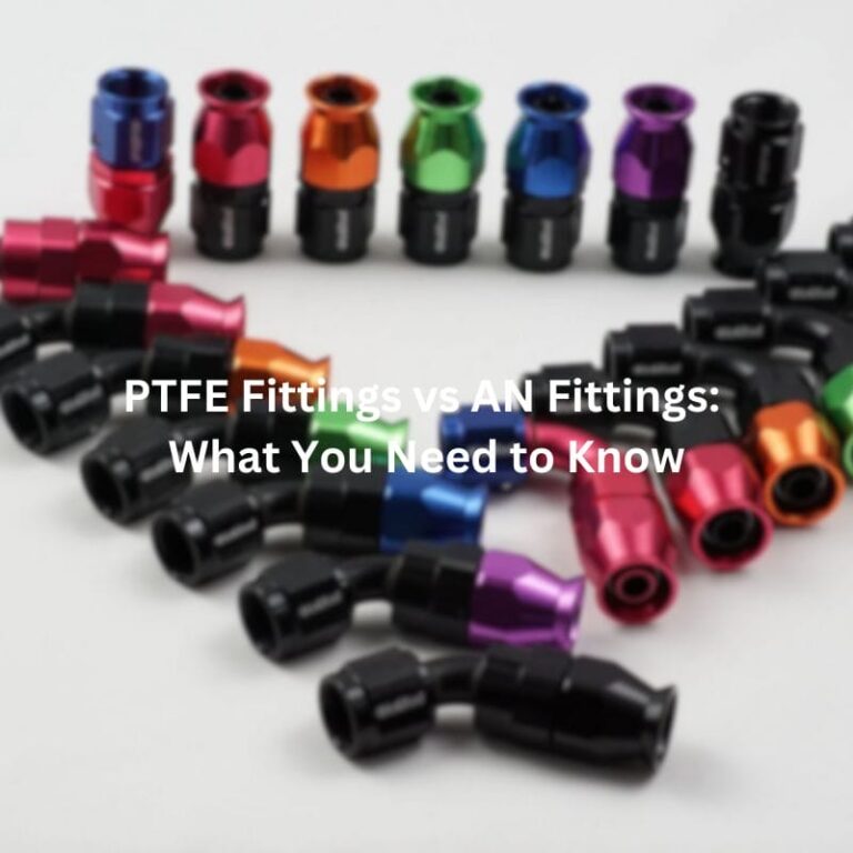
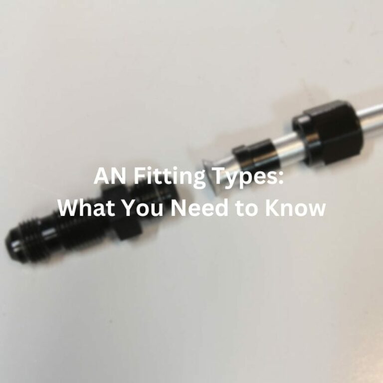
PTFE Fittings vs AN Fittings: What You Need to Know
Table of Contents
Introduction
The wrong fitting can lead to leaks, system failures, and costly downtime, making the selection process critical for engineers and technicians alike. Among the myriad of options available, PTFE (Polytetrafluoroethylene) and AN (Army-Navy) fittings stand out for their unique properties and applications. The purpose of this post is to provide a comprehensive comparison between PTFE and AN fittings, delving into their characteristics, advantages, disadvantages, and common applications.
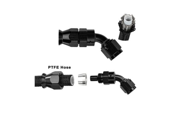
Understanding PTFE Fittings
What PTFE is
PTFE, commonly known as Teflon, is a synthetic fluoropolymer of tetrafluoroethylene. It is renowned for its remarkable non-stick properties, which are a result of the strong bonds between carbon and fluorine atoms in its molecular structure. These bonds create a highly stable, non-reactive surface that resists adhesion from almost all substances.
How PTFE Fittings Are Manufactured
PTFE fittings are manufactured through a process known as molding and machining. The raw PTFE material is first molded into a basic shape through compression molding. This involves placing PTFE powder into a mold and applying heat and pressure to form a solid shape. Once the basic shape is formed, it undergoes machining to achieve precise dimensions and specifications. This machining process ensures that the fittings meet the stringent requirements necessary for high-performance applications.
Key Characteristics
Chemical Resistance
One of the standout features of PTFE is its exceptional chemical resistance. It is virtually inert to almost all chemicals, making it an ideal choice for applications involving aggressive or corrosive substances. This property ensures that PTFE fittings can be used in environments where other materials might degrade or fail.
Temperature Tolerance
PTFE can withstand a wide range of temperatures, from as low as -200°C to as high as 260°C. This broad temperature tolerance makes PTFE fittings suitable for both cryogenic applications and high-temperature processes. This versatility is particularly valuable in industries where temperature extremes are common.
Durability and Flexibility
PTFE is not only durable but also flexible. Its mechanical properties remain stable over a wide range of temperatures and pressures, ensuring longevity and reliability in demanding applications. The material’s flexibility also allows it to absorb and distribute stress, reducing the likelihood of fractures or leaks.
Common Applications
Industries Using PTFE Fittings
PTFE fittings are widely used in various industries due to their unique properties. In the chemical industry, they are favored for their resistance to corrosive chemicals. The pharmaceutical industry relies on PTFE fittings for their purity and non-reactivity, ensuring that sensitive drugs and chemicals remain uncontaminated. In the food processing industry, PTFE’s non-stick properties make it ideal for applications where cleanliness and hygiene are paramount.
Specific Use Cases
PTFE fittings are particularly effective in corrosive environments where exposure to harsh chemicals is a concern. They are also used in high-temperature systems, such as steam lines and heat exchangers, where other materials might fail. Additionally, PTFE fittings are found in applications requiring non-stick surfaces, such as in the handling of sticky or viscous materials.
Advantages
Superior Chemical and Temperature Resistance
The primary advantage of PTFE fittings is their unmatched chemical and temperature resistance. This makes them suitable for a wide range of applications where other materials would quickly degrade. PTFE’s resistance to chemical attack ensures long-term reliability and safety in corrosive environments.
Non-Stick and Low Friction Properties
PTFE’s non-stick properties are another significant advantage. This reduces the risk of material build-up and blockages, ensuring smooth operation in various applications. The low friction properties also contribute to the longevity of the fittings by minimizing wear and tear.
Disadvantages
Potential Cost Implications
Despite their many advantages, PTFE fittings can be more expensive than other types of fittings. The cost of raw PTFE material, combined with the specialized manufacturing processes required, can result in higher prices. However, this cost is often justified by the increased performance and longevity of PTFE fittings.
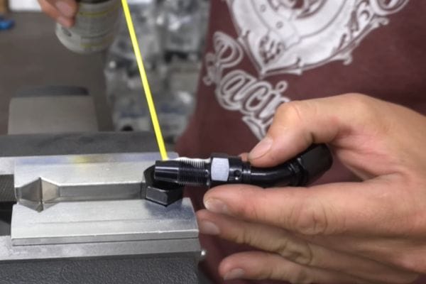
Installation Considerations and Challenges
Installing PTFE fittings can present some challenges. Due to their flexibility, special care must be taken during installation to ensure a proper seal. Misalignment or over-tightening can lead to leaks or damage. Additionally, PTFE’s non-stick properties can make it difficult to handle and position the fittings during installation.
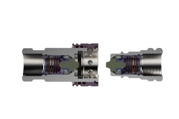
Understanding AN Fittings
Definition and History
AN fittings, short for Army-Navy fittings, originated in the military sector. They were developed during World War II to meet the stringent demands of military applications, which required reliable and standardized fittings for fuel and hydraulic systems in aircraft and other vehicles. The military’s need for high-quality, leak-proof connections that could withstand extreme conditions led to the creation of the AN standard, which has since become widely adopted in various industries.
Materials Used in AN Fittings
AN fittings are typically made from materials known for their strength and durability, such as aluminum, stainless steel, and, occasionally, titanium. Aluminum fittings are lightweight and resistant to corrosion, making them ideal for aerospace and automotive applications. Stainless steel fittings, while heavier, offer superior strength and resistance to both high pressures and corrosive environments. Titanium fittings, though less common due to their high cost, provide an excellent strength-to-weight ratio and outstanding resistance to corrosion.
Key Characteristics
Precision and Reliability
One of the hallmarks of AN fittings is their precision engineering. These fittings are manufactured to tight tolerances, ensuring a perfect fit and reliable performance. This precision translates into high reliability, making AN fittings a preferred choice for critical applications where failure is not an option.
Pressure Rating and Mechanical Strength
AN fittings are designed to handle high-pressure environments. Their robust construction allows them to withstand significant mechanical stress and high pressures without deforming or leaking. This makes them suitable for demanding applications, such as fuel and hydraulic systems in high-performance vehicles and aircraft.
Common Applications
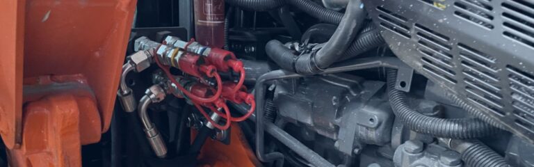
Use in Aerospace, Automotive, and Motorsports
AN fittings are extensively used in the aerospace industry, where they connect fuel, hydraulic, and other fluid systems. Their reliability and high-pressure tolerance make them ideal for use in aircraft. In the automotive and motorsports industries, AN fittings are commonly used in high-performance fuel systems, oil lines, and brake systems, where durability and leak-proof connections are crucial.
Specific Scenarios
In high-pressure fuel systems, AN fittings provide the necessary reliability and strength to ensure safe and efficient fuel delivery. In hydraulic lines, particularly in aviation and automotive applications, AN fittings maintain the integrity of the system under extreme pressures and temperatures. Their versatility also extends to custom applications, where precise and reliable connections are required.
Advantages
High-Pressure Handling
AN fittings are specifically designed to handle high-pressure environments. Their construction and materials allow them to maintain integrity and prevent leaks even under extreme conditions. This makes them ideal for applications where pressure management is critical.
Reusability and Ease of Installation
AN fittings are designed for easy installation and removal. They can be reused multiple times without compromising their integrity, making them a cost-effective solution for systems that require frequent maintenance or modifications. The threaded connections ensure a secure fit, while the precision engineering guarantees a leak-proof seal.
Disadvantages
Compatibility Issues with Different Materials
One of the challenges with AN fittings is ensuring compatibility with different materials. While they work well with materials like aluminum and stainless steel, mixing materials (e.g., using an aluminum fitting with a stainless steel component) can lead to galvanic corrosion, which can weaken the fitting and lead to leaks. Care must be taken to use compatible materials to avoid these issues.
Higher Cost for Certain Materials
AN fittings, particularly those made from stainless steel or titanium, can be more expensive than other types of fittings. The high cost of these materials, combined with the precision manufacturing required, contributes to the higher price. However, the benefits of reliability, strength, and reusability often outweigh the initial cost for many applications.
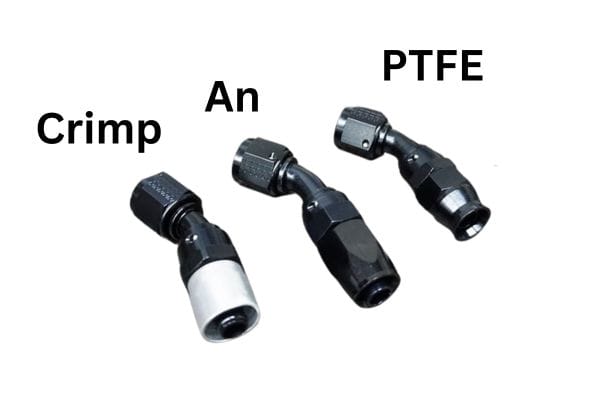
Detailed Comparison of PTFE and AN Fittings
Material and Construction
Differences in Materials Used
PTFE and AN fittings are constructed from distinct materials, each chosen for its specific properties and suitability for different applications. PTFE fittings are made from polytetrafluoroethylene, a synthetic fluoropolymer known for its exceptional chemical resistance and non-reactivity. This material is highly stable and inert, making it ideal for use in environments where exposure to harsh chemicals and high temperatures is common.
On the other hand, AN fittings are typically manufactured from metals such as aluminum, stainless steel, and occasionally titanium. Aluminum AN fittings are lightweight and resistant to corrosion, making them suitable for applications where weight is a critical factor, such as in the aerospace and automotive industries. Stainless steel AN fittings, while heavier, offer superior strength and resistance to both high pressures and corrosive environments, making them ideal for use in more demanding applications.
Impact on Performance and Durability
The choice of material has a significant impact on the performance and durability of the fittings. PTFE fittings, with their superior chemical resistance and temperature tolerance, are exceptionally durable in environments where other materials might degrade or fail. They maintain their integrity even when exposed to aggressive chemicals and extreme temperatures, ensuring long-term reliability.
AN fittings, with their robust metal construction, excel in high-pressure environments. Aluminum AN fittings offer a good balance of strength and weight, while stainless steel fittings provide unmatched durability and pressure tolerance. However, the performance of AN fittings can be affected by material compatibility issues, such as galvanic corrosion when different metals are used together.
Pressure Ratings
Pressure rating is a critical factor in selecting fittings for any application. PTFE fittings typically have moderate pressure ratings, suitable for most chemical processing and fluid transfer applications. Their ability to maintain a reliable seal under various pressure conditions makes them ideal for use in systems where chemical resistance is more critical than high-pressure tolerance.
AN fittings, designed originally for military applications, have high-pressure ratings. They are engineered to withstand significant mechanical stress and maintain their integrity under extreme pressures, making them suitable for high-performance applications such as fuel and hydraulic systems in aircraft and race cars.
Temperature Ranges
PTFE fittings can operate effectively across a broad temperature range, from as low as -200°C to as high as 260°C. This wide temperature tolerance makes PTFE fittings versatile and suitable for both cryogenic applications and high-temperature processes.
AN fittings also offer a wide temperature range, though it varies depending on the material used. Aluminum AN fittings typically handle temperatures up to 200°C, while stainless steel fittings can tolerate even higher temperatures. This makes AN fittings suitable for high-temperature applications where both pressure and thermal stability are required.
Chemical Compatibility
Chemical compatibility is another crucial factor to consider. PTFE is renowned for its chemical inertness, being virtually immune to almost all chemicals. This makes PTFE fittings ideal for use in chemical processing, pharmaceutical, and food industries, where exposure to aggressive chemicals is common.
AN fittings, made from metals like aluminum and stainless steel, also offer good chemical resistance but are not as universally inert as PTFE. Aluminum fittings are prone to corrosion when exposed to certain chemicals, while stainless steel fittings offer better resistance but can still be affected by highly corrosive substances. Careful consideration of the chemicals involved in the application is necessary when choosing AN fittings.
Installation and Maintenance
Ease of Installation
PTFE fittings, due to their flexibility and non-stick properties, require careful handling during installation to ensure a proper seal. Over-tightening or misalignment can lead to leaks, making precise installation techniques essential. However, once installed correctly, PTFE fittings provide reliable, leak-proof connections.
AN fittings are designed for ease of installation and removal. The threaded connections ensure a secure fit, and the precision engineering of AN fittings makes them straightforward to install without the need for special tools or techniques. This ease of installation, combined with their reusability, makes AN fittings a practical choice for applications where frequent maintenance or reconfiguration is required.
Maintenance Requirements and Longevity
Maintenance requirements for PTFE fittings are generally low due to their chemical resistance and durability. They can withstand harsh conditions without degrading, reducing the need for frequent replacements. However, regular inspections are necessary to ensure the fittings remain securely in place and free from damage.
AN fittings, with their robust construction, also require minimal maintenance. Their high-pressure tolerance and mechanical strength mean they can withstand significant wear and tear. However, it is essential to monitor for signs of corrosion, especially when different metals are used together, to prevent potential failures. Regular maintenance checks and proper installation can extend the lifespan of AN fittings, ensuring long-term reliability.
Conclusion
Choosing between PTFE and AN fittings requires a thorough understanding of the specific requirements of your application. Consider factors such as chemical exposure, pressure, temperature conditions, and the need for ease of installation and maintenance. PTFE fittings are the best choice for environments where chemical resistance and temperature stability are paramount. AN fittings, with their high-pressure tolerance and mechanical strength, are better suited for high-performance and high-stress applications.
FAQ
PTFE fittings are ideal for applications requiring high chemical resistance and temperature tolerance, such as chemical processing, pharmaceuticals, and food industries.
AN fittings are commonly used in aerospace, automotive, and motorsports industries due to their high-pressure handling capabilities and robust construction.
While PTFE fittings have moderate pressure ratings suitable for many applications, they may not be the best choice for extremely high-pressure environments where AN fittings would be more appropriate.
Yes, AN fittings are designed for ease of installation and removal, making them reusable without compromising their integrity.
AN fittings are typically made from materials like aluminum, stainless steel, and titanium, chosen for their strength and durability.
Do PTFE fittings require special installation techniques?
Yes, PTFE fittings require careful handling during installation to ensure a proper seal and prevent leaks due to their flexible and non-stick properties.
It’s recommended to inspect your brass pipe fittings regularly, at least every few months, to check for signs of leaks, corrosion, or wear. Regular maintenance helps identify and address any issues early, ensuring the longevity and reliability of your piping system.


