Camlock Fittings Specification The Detailed Guide

Camlock Fittings Specification: The Detailed Guide

Camlock Fittings Specification: The Detailed Guide

Table of Contents

Introduction

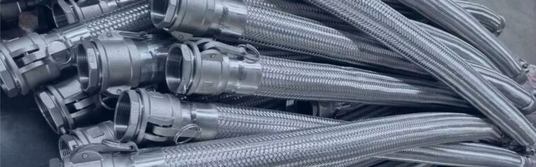
Camlock couplings, also known as cam and groove couplings, are vital components in fluid handling systems, designed for quick and secure hose connections. These couplings play a crucial role in various industries by providing a reliable means to connect and disconnect hoses with minimal effort, ensuring efficient and safe fluid transfer. This guide aims to provide a comprehensive overview of camlock couplings, covering their technical specifications, various types, material options, and installation and maintenance best practices.

What Are Camlock Couplings?

Camlock couplings, also known as cam and groove couplings, are specialized connectors used to quickly and securely join hoses and pipes in various fluid transfer systems. These couplings are designed for ease of use, allowing for fast connections and disconnections without the need for tools. Their primary function is to provide a leak-proof connection between two hoses or a hose and a pipe, ensuring that fluids can be transferred efficiently and safely.

Definition and Functionality

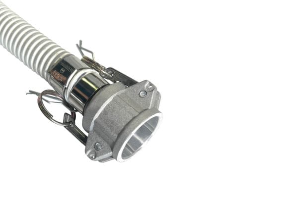
Camlock couplings operate using a simple yet effective mechanism. The coupling consists of two main parts: the coupler (also known as the female part) and the adapter (the male part). The coupler features two cam arms that pivot open to accept the adapter. When the adapter is inserted into the coupler, the cam arms are pushed down, locking the adapter securely in place. This locking action creates a tight seal, preventing leaks and ensuring that the fluid flows smoothly through the connection. The design of camlock couplings allows for rapid connections and disconnections, making them ideal for applications where speed and efficiency are critical.

Camlock Fittings different Types

Key Components

Cam Arms: These are the levers on the coupler that are used to lock the adapter in place. When the cam arms are pulled down, they create a secure connection between the coupler and the adapter. The cam arms are typically made of durable materials to withstand repeated use and resist wear and tear.

Coupler: The coupler is the female part of the camlock coupling. It contains the cam arms and is designed to receive the adapter. The coupler’s internal design ensures a tight seal when the adapter is inserted and locked into place.

Adapter: The adapter is the male part of the camlock coupling. It is inserted into the coupler to form a connection. The adapter is designed to fit snugly within the coupler, and when the cam arms are engaged, it creates a secure and leak-proof seal.

Common Applications

Camlock couplings are used across a wide range of industries due to their versatility, reliability, and ease of use. Some of the most common industries where camlock couplings are utilized include:

Agriculture: In agriculture, camlock couplings are often used for irrigation systems, chemical transfer, and the handling of fertilizers and pesticides. Their ability to quickly connect and disconnect hoses makes them ideal for field use where efficiency is key.

Chemical Processing: The chemical industry relies on camlock couplings for the safe transfer of various chemicals. These couplings are compatible with a wide range of chemicals and can be made from materials that resist corrosion and chemical damage.

Oil and Gas: In the oil and gas industry, camlock couplings are used for the transfer of fuels, lubricants, and other hydrocarbons. Their durability and ability to handle high pressures and temperatures make them suitable for the demanding conditions of this industry.

Water Treatment: Camlock couplings are commonly used in water treatment facilities for connecting hoses and pipes that transport water and other fluids. Their quick-connect design allows for efficient maintenance and system adjustments.

Typical Fluids Handled

Camlock couplings are capable of handling a variety of fluids, making them a versatile choice for many applications. Some of the typical fluids that are commonly transferred through camlock couplings include:

Water: Whether in agriculture, construction, or water treatment, camlock couplings are frequently used to transfer water due to their reliability and ease of use.

Chemicals: Camlock couplings made from materials like stainless steel or polypropylene are often used in chemical processing to handle corrosive and hazardous fluids safely.

Fuels: In the oil and gas industry, camlock couplings are used to transfer fuels such as gasoline, diesel, and kerosene, where a secure and leak-proof connection is essential.

Types of Camlock Couplings

Camlock couplings come in various types, each designed for specific applications and configurations. Understanding these types is crucial for selecting the right coupling for your needs. Below is a detailed overview of the standard types, special variants, and a comparison of their advantages and disadvantages.

Standard Types

Type A

Description: Type A camlock couplings have a male adapter and a female threaded end. They are typically used to connect hoses to female threaded pipes or equipment.

Applications: Commonly used in applications where a secure threaded connection is required, such as connecting hoses to pumps or valves.

Type B

Description: Type B couplings feature a female coupler and a male threaded end. They are often used to connect hoses to male-threaded pipes or equipment.

Applications: Ideal for situations where hoses need to be attached to equipment with a male thread, such as in chemical processing or water transfer systems.

Type C

Description: Type C couplings have a female coupler and a hose shank. They are used to connect hoses with a camlock coupling at one end and a plain hose at the other.

Applications: Common in agriculture and water treatment, where quick hose connections are needed.

Type D

Description: Type D couplings consist of a female coupler with a female threaded end. They are used to connect male-threaded pipes or equipment to hoses.

Applications: Frequently used in chemical processing and oil and gas industries, where secure connections to threaded equipment are necessary.

Type E

Description: Type E camlock couplings have a male adapter with a hose shank. They are used to connect hoses to a female coupler.

Applications: Often found in applications requiring quick connections between hoses, such as in the transport of liquids.

Type F

Description: Type F couplings feature a male adapter with a male threaded end. They are used to connect hoses to female threaded pipes or equipment.

Applications: Suitable for environments where a hose needs to be connected to female-threaded equipment, like pumps or tanks.

camlock fitting types factory

Special Variants

Dust Caps and Dust Plugs

Overview: Dust caps (Type DC) and dust plugs (Type DP) are designed to protect camlock couplings when not in use. They prevent dirt, dust, and debris from entering the coupling, which could compromise the seal and cause leaks.

Specific Uses: These components are especially useful in environments with high cleanliness requirements or in outdoor applications where the couplings are exposed to harsh conditions.

High-Pressure Variants and Materials

Overview: For applications that involve extreme conditions, such as high pressures or temperatures, special camlock couplings are available. These variants are made from materials like stainless steel or brass, which offer enhanced durability and resistance to corrosion.

Specific Uses: High-pressure camlock couplings are commonly used in the oil and gas industry, chemical processing, and any application where standard couplings might fail due to high stress.

Type

Advantages

Disadvantages

Best Use Cases

Type
A

Secure threaded connection;
durable

Requires precise matching
with female thread

Connecting hoses to
equipment with female
threads

Type
B

Versatile;easy to use

Limited to applications with
male threads

Attaching hoses to
equipment with male threads

Type

C

Quick connection to plain

hoses

Requires hose clamps for

secure fit

Agricultural and water

treatment applications

Type
D

Secure connection to male
threaded equipment

Requires precise matching
with male thread

Chemical processing,oil and
gas

Type

E

Quick hose connection;

versatile

Requires hose clamps for

secure fit

Liquid transport,industrial

applications

Type

F

Simple connection to female

threads

Requires precise matching

with female thread

Connecting hoses to female-

threaded equipment

Type DC

Protects against
contamination

Only for non-operational
use

Food processing,outdoor
applications

Type
DP

Prevents dirt and damage

Only for non-operational
use

Hygiene-critical industries,
outdoor settings

Material Specifications

Choosing the right material for camlock couplings is critical for ensuring their performance, durability, and safety in various applications. Below is a detailed overview of the common materials used in camlock couplings, the selection criteria for these materials, and the importance of gasket materials in sealing performance.

Aluminum

Overview: Aluminum is one of the most widely used materials for camlock couplings due to its lightweight nature and good corrosion resistance.

Material Properties: Aluminum is resistant to corrosion, especially from water and certain chemicals. It has a moderate strength-to-weight ratio, making it suitable for applications where weight is a concern.

Compatibility: Aluminum camlock couplings are compatible with water, oils, and some chemicals, but they may not be suitable for highly acidic or alkaline fluids.

Stainless Steel

Overview: Stainless steel is known for its superior strength and resistance to corrosion, making it a preferred material in harsh environments.

Material Properties: Stainless steel offers excellent resistance to corrosion from a wide range of chemicals, as well as high temperatures. It is also highly durable and capable of withstanding high pressure.

Compatibility: Stainless steel camlock couplings are ideal for use with corrosive chemicals, oils, steam, and food-grade applications.

Brass

Overview: Brass is valued for its good corrosion resistance, machinability, and antimicrobial properties.

Material Properties: Brass has good corrosion resistance, especially in water-based applications. It is also relatively easy to machine, making it suitable for precision parts.

Compatibility: Brass camlock couplings are commonly used in applications involving water, petroleum products, and mild chemicals. However, brass is not recommended for use with ammonia or certain acids.

Polypropylene

Overview: Polypropylene is a lightweight, cost-effective plastic material that is resistant to many chemicals.

Material Properties: Polypropylene is resistant to many acids, bases, and solvents, but it has lower mechanical strength compared to metal couplings. It is also not suitable for high-temperature applications.

Compatibility: Polypropylene camlock couplings are typically used in agricultural applications, chemical processing, and low-pressure fluid handling systems.

Nylon

Overview: Nylon is another plastic material used for camlock couplings, offering higher strength than polypropylene.

Material Properties: Nylon has good mechanical strength, chemical resistance, and impact resistance. However, it can absorb moisture, which may affect its dimensions and performance.

Compatibility: Nylon camlock couplings are suitable for a wide range of chemicals, oils, and fuels, particularly in situations where lightweight and durable materials are needed.

Gasket Materials

Buna-N (Nitrile Rubber): Buna-N is a common gasket material known for its excellent resistance to petroleum-based fluids, oils, and some chemicals. It has good mechanical properties but limited temperature resistance.

EPDM (Ethylene Propylene Diene Monomer): EPDM offers excellent resistance to water, steam, and certain chemicals, especially in outdoor environments. It has a broad temperature range but is not suitable for petroleum-based products.

PTFE (Polytetrafluoroethylene): PTFE, also known as Teflon, is highly resistant to almost all chemicals and can withstand extreme temperatures. It provides excellent sealing performance, especially in aggressive chemical environments.

Sizing and Dimensions

Standard Sizes

Camlock couplings come in a range of standard sizes to accommodate various hose and pipe diameters. The most common sizes range from 1/2 inch to 6 inches, with each size corresponding to the internal diameter (ID) of the hose or pipe the coupling will connect to.

1/2″ and 3/4″: Often used in small-scale applications such as laboratories or small equipment connections.

1″ to 3″: Common in agriculture, chemical processing, and light industrial applications.

4″ and 6″: Typically used in larger industrial applications, such as oil and gas, where large volumes of fluid need to be transferred quickly.

How to Measure Camlock Couplings Correctly

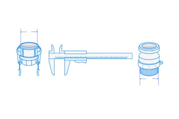
To ensure a proper fit, it’s important to measure camlock couplings accurately. Here’s a step-by-step guide:

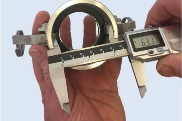
Determine the Size: Measure the internal diameter (ID) of the hose or pipe that will connect to the camlock coupling. The coupling size should match this measurement.

Measure the Coupler and Adapter: The coupler’s internal diameter and the adapter’s external diameter should align with the hose or pipe size. Ensure that the cam arms fit securely around the adapter when locked.

Check Thread Size (if applicable): For couplings with threaded ends, measure the thread size using a thread gauge to ensure compatibility with the connecting equipment.

Verify Overall Length: Measure the total length of the coupling assembly to ensure it fits within the available space.

Camlock Fittings measure

Interchangeability Across Sizes

Ensuring Compatibility

Camlock couplings are designed to be interchangeable across manufacturers, provided they conform to recognized standards. Standardization ensures that a camlock coupling from one manufacturer will fit and function correctly with a coupling from another manufacturer. To ensure compatibility:

Adhere to Standards: Use camlock couplings that comply with international standards such as ISO 7241, MIL-C-27487, or EN 14420-7. These standards define the dimensions and tolerances required for interchangeability.

Cross-Check Manufacturer Specifications: Verify that the couplings you are using match the specifications provided by the manufacturer, especially when mixing products from different sources.

Dimensional Tolerances

Importance of Precise Dimensions

Precise dimensions are critical for ensuring a leak-free connection. Even slight deviations from the standard dimensions can result in poor sealing, leading to leaks or coupling failure. Accurate dimensions also ensure that the cam arms lock securely, preventing accidental disconnection.

How Tolerances Are Maintained

Manufacturing Precision: High-quality camlock couplings are manufactured using precision machining processes that ensure tight dimensional tolerances. Computer Numerical Control (CNC) machining and quality control measures like coordinate measuring machines (CMM) help maintain these tolerances.

Quality Control: Regular inspections and adherence to quality management systems (e.g., ISO 9001) ensure that each coupling meets the required dimensional standards. This helps prevent issues related to misalignment or improper sealing.

Pressure and Temperature Ratings

Understanding Pressure Ratings

Pressure ratings for camlock couplings vary depending on the material and size of the coupling. These ratings indicate the maximum pressure the coupling can safely handle without failure.

Material Impact: Different materials have varying pressure ratings. For example, stainless steel camlock couplings typically have higher pressure ratings than polypropylene couplings due to the material’s strength.

Size Impact: Larger couplings generally have lower pressure ratings because the increased surface area can result in higher forces being exerted on the coupling.

Factors Affecting Pressure Ratings

Temperature: Higher temperatures can reduce the pressure rating of a coupling as materials tend to weaken when exposed to heat. For instance, a stainless steel coupling rated for 250 PSI at 70°F might only be rated for 200 PSI at 150°F.

Fluid Type: The type of fluid being transferred can also affect pressure ratings. Fluids with higher viscosities or those that are corrosive may require couplings with higher pressure ratings or those made from more resistant materials.

Temperature Limitations

Operating Temperature Ranges

Each material used in camlock couplings has a specific operating temperature range:

Stainless Steel: -150°F to 500°F

Brass: -50°F to 400°F

Aluminum: -50°F to 225°F

Polypropylene: 0°F to 150°F

Nylon: -20°F to 200°F

Impact on Material Selection and Performance

High-Temperature Applications: For applications involving steam or hot fluids, stainless steel or brass is preferred due to their high-temperature tolerance.

Low-Temperature Applications: For cold environments, materials like stainless steel and nylon are often used due to their durability and resistance to brittleness at low temperatures.

Testing and Certification

Standards and Testing Protocols

Camlock couplings must meet various industry standards to ensure their reliability under pressure and temperature conditions. Common standards include:

ISO 7241: Specifies performance requirements for hydraulic fluid power quick-action couplings.

MIL-C-27487: Military standard for camlock couplings, ensuring they meet stringent durability and performance criteria.

Testing Procedures

Pressure Testing: Couplings are tested at their rated pressure to ensure they can handle the maximum specified load without leaking or failing.

Temperature Testing: Materials are subjected to temperature extremes to verify that they maintain their integrity and performance under varying thermal conditions.

Importance of Certifications

Certifications from recognized bodies (e.g., ISO, ANSI, MIL-spec) assure that the camlock couplings have been tested and meet the required safety and performance standards. These certifications are crucial for ensuring the safety and reliability of fluid handling systems, especially in regulated industries such as chemical processing, oil and gas, and pharmaceuticals.

Conclusion

For optimum performance and safety, consider consulting an expert or supplier when selecting a cam locking fitting. We can provide advice tailored to your specific needs and help you understand the various options available. In addition, you can learn more about resources or products related to cam lock couplings. Whether you’re upgrading an existing system or planning a new installation, having the right knowledge and support is key to achieving a reliable and efficient fluid-handling system.

FAQ

Camlock couplings are used for quickly connecting and disconnecting hoses and pipes in fluid transfer systems across various industries, such as agriculture, chemical processing, and oil and gas.

Camlock couplings are commonly made from materials like aluminum, stainless steel, brass, polypropylene, and nylon, each suited for different fluids and environmental conditions.

To select the correct size, match the internal diameter (ID) of the camlock coupling to the hose or pipe it will connect to. Sizes typically range from 1/2 inch to 6 inches.

Yes, but the pressure and temperature ratings depend on the material of the coupling. For high-pressure or high-temperature applications, materials like stainless steel or brass are recommended.

Yes, camlock couplings that comply with industry standards (like ISO 7241 or MIL-C-27487) are generally interchangeable between different manufacturers.

Regularly inspect camlock couplings for wear and tear, clean them, and replace components like gaskets and cam arms as needed to ensure they remain leak-free and reliable.

Stuck Bulkhead Hydraulic Fittings Top Solutions You Need

Stuck Bulkhead Hydraulic Fittings? Top Solutions You Need

Stuck Bulkhead Hydraulic Fittings? Top Solutions You Need

Introduction

Bulkhead hydraulic fittings are a crucial component in hydraulic systems, serving as the connecting point where hoses, pipes, or tubes pass through a barrier, such as a panel or a bulkhead, without compromising the system’s integrity. Despite their importance, bulkhead hydraulic fittings can sometimes become problematic, especially when they get stuck. The purpose of this post is to provide a comprehensive guide to understanding and resolving issues related to stuck bulkhead hydraulic fittings.

Understanding Bulkhead Hydraulic Fittings

Definition and Function

Bulkhead hydraulic fittings are specialized components used in hydraulic systems to provide a secure and leak-proof connection between hoses, tubes, or pipes as they pass through a barrier, such as a bulkhead, wall, or panel. These fittings are designed to maintain the integrity of the hydraulic system while ensuring that the fluid flow is not compromised. The primary function of bulkhead fittings is to create a reliable, sealed connection that can withstand the high pressures and harsh conditions typical of hydraulic environments.

In essence, bulkhead fittings serve as a bridge between different sections of a hydraulic system, allowing the fluid to move from one compartment to another without any leakage. This is particularly important in applications where the hydraulic components are separated by structural barriers, and the connection needs to be maintained without compromising the barrier’s integrity. By securing the passage of hydraulic fluid through these barriers, bulkhead fittings play a crucial role in maintaining the overall efficiency and reliability of hydraulic systems.

Types of Bulkhead Hydraulic Fittings

Bulkhead hydraulic fittings come in various types, each designed to suit specific applications and configurations within hydraulic systems. The most common types include:

Straight Bulkhead Fittings: These are the simplest form of bulkhead fittings, featuring a straight connection that allows fluid to pass directly through the fitting. They are typically used in situations where the hose or tube needs to pass straight through a barrier without any change in direction.

Elbow Bulkhead Fittings: These fittings are designed to change the direction of the fluid flow as it passes through a barrier. They are available in 90-degree and 45-degree configurations, making them ideal for applications where the hydraulic line needs to navigate around obstacles or make a turn.

Tee Bulkhead Fittings: Tee fittings allow for the connection of three hydraulic lines, with one line passing straight through the barrier and the other two branching off at right angles. This configuration is useful in systems where multiple hydraulic lines need to be connected through a single barrier point.

JIC Bulkhead hydraulic fitting manufacturer

Materials and Construction


Bulkhead hydraulic fittings are typically made from durable materials that can withstand the demanding conditions of hydraulic systems. The most common materials used include:

Steel: Steel fittings are known for their strength and durability, making them suitable for high-pressure applications. However, steel is prone to corrosion, so it is often coated or treated to resist rust and wear.

Stainless Steel: Stainless steel fittings offer excellent corrosion resistance, making them ideal for applications where exposure to moisture, chemicals, or other corrosive elements is a concern. They are commonly used in marine, chemical processing, and food and beverage industries.

Brass: Brass fittings provide a good balance of strength and corrosion resistance, and they are often used in lower-pressure applications. Brass is also easier to work with and provides a good seal, making it a popular choice for general-purpose hydraulic systems.

Causes of Stuck Bulkhead Hydraulic Fittings

Corrosion

Corrosion is one of the most common reasons bulkhead hydraulic fittings become stuck. Over time, exposure to moisture, chemicals, or harsh environmental conditions can lead to the oxidation of metal fittings, particularly those made from steel or other non-corrosion-resistant materials. When corrosion occurs, it creates a layer of rust or other corrosive products on the surface of the fitting, which can cause the threads to seize up, making it nearly impossible to loosen or remove the fitting without damaging it.

Identifying Signs of Corrosion:

Before a fitting becomes completely stuck, there are often warning signs that corrosion is taking hold. These signs include discoloration of the metal, pitting or surface roughness, and the presence of rust or other corrosive residues around the fitting. Regular inspections can help identify these early signs, allowing for preventive maintenance or replacement before the fitting becomes a more serious issue.

Hydraulic Bulkhead Fittings Fail

Over-Tightening

Over-tightening during the installation process is another major cause of stuck bulkhead hydraulic fittings. When a fitting is tightened beyond its recommended torque, the threads can become damaged or distorted, leading to a condition known as “galling.” Galling occurs when the metal surfaces of the threads adhere to each other under pressure, making it extremely difficult to loosen the fitting without causing further damage.

Recognizing Over-Tightened Fittings:

There are a few telltale signs that a fitting has been over-tightened. These include difficulty in loosening the fitting, visible damage to the threads, or even a “frozen” feel when attempting to unscrew the fitting. If a fitting requires excessive force to install or remove, it may have been over-tightened. Using a torque wrench during installation can help ensure that fittings are tightened to the manufacturer’s specifications, reducing the risk of over-tightening.

Contamination and Debris

Contamination by foreign particles, such as dirt, dust, or metal shavings, can also lead to stuck bulkhead hydraulic fittings. When these contaminants get into the threads or the sealing surfaces of the fitting, they can create friction and resistance, making it difficult to tighten or loosen the fitting properly. In some cases, the contaminants can cause the fitting to bind, leading to a stuck condition.

Prevention Tips:

To prevent contamination, it’s essential to keep the work area clean during installation and maintenance. Ensuring that fittings are kept in a clean environment and using protective caps when they are not in use can help minimize the introduction of debris. Additionally, using thread sealants or lubricants that repel contaminants can further protect the threads from becoming fouled.

Wear and Tear

Hydraulic systems are often subjected to high levels of pressure and mechanical stress, which can cause wear and tear on bulkhead fittings over time. As these fittings age, the threads can become worn, and the sealing surfaces may degrade, making it more likely for the fitting to become stuck. Prolonged use in harsh conditions, such as extreme temperatures or heavy vibrations, can exacerbate this wear, leading to a gradual degradation of the fitting’s integrity.

When to Consider Replacement:

Regular inspection and maintenance are critical to identifying wear and tear before it becomes a problem. Signs that a fitting is nearing the end of its useful life include visible thread wear, leaks, or difficulty in adjusting or removing the fitting. If any of these signs are present, it’s advisable to replace the fitting before it becomes stuck and more challenging to deal with.

Improper Installation

Improper installation is a significant contributor to stuck bulkhead hydraulic fittings. Common mistakes include misalignment of the fitting during installation, using the wrong type of fitting for the application, or failing to use the correct installation tools. These errors can cause the fitting to bind or seize during installation, making it difficult to adjust or remove later.

Best Practices for Proper Installation:

To avoid these issues, it’s essential to follow the manufacturer’s installation guidelines carefully. Ensure that the fitting is aligned correctly before tightening and that the correct tools are used to apply the appropriate amount of torque. Additionally, selecting the right type of fitting for the specific application, considering factors like pressure, temperature, and environmental exposure, can prevent issues related to improper installation.

Diagnosing Stuck Bulkhead Hydraulic Fittings

Diagnosing stuck bulkhead hydraulic fittings is a critical step in resolving the issue effectively and safely. A thorough diagnosis allows you to identify the underlying cause of the problem and decide on the best course of action, whether it involves freeing the fitting or replacing it altogether.

Visual Inspection

The first step in diagnosing a stuck bulkhead hydraulic fitting is a careful visual inspection. This simple yet effective method can often reveal the root cause of the problem, allowing you to take appropriate action.

What to Look For:

Corrosion: Look for signs of rust or other corrosion products around the fitting. Corrosion can often appear as a reddish-brown discoloration on steel fittings, or as a dull, chalky residue on stainless steel or brass fittings. Corrosion is a common cause of fittings seizing up, as it can cause the threads to bind together.

Debris and Contamination: Check the area around the fitting for any signs of debris, dirt, or other contaminants. These can become lodged in the threads or sealing surfaces, preventing the fitting from moving freely. A buildup of grime or other particles is a strong indicator that contamination might be the cause of the problem.

Physical Damage: Inspect the fitting for any signs of physical damage, such as dents, cracks, or thread deformation. Damage to the fitting can make it difficult to loosen or remove, and it may indicate that the fitting has been over-tightened or improperly installed.

Signs of a Stuck Fitting:

If the fitting appears to be corroded, has visible debris, or shows signs of damage, these are clear indicators that it is stuck due to these factors. Additionally, if the fitting does not move when an appropriate amount of force is applied, it is likely stuck and requires further diagnosis.

Using Diagnostic Tools

In cases where a visual inspection does not reveal the cause of the problem, or where more detailed analysis is needed, diagnostic tools can be invaluable in determining why a bulkhead hydraulic fitting is stuck.

Torque Wrenches:

A torque wrench can be used to measure the amount of force required to attempt to loosen the fitting. If the torque required exceeds the recommended value for the fitting, it is likely stuck. Using a torque wrench can also help prevent over-tightening, which is a common cause of stuck fittings.

Inspection Cameras:

Inspection cameras, also known as borescopes, can be used to get a closer look at the threads and the interior of the fitting. This tool is particularly useful for identifying internal corrosion, debris, or damage that might not be visible during a standard visual inspection.

Penetrating Oil and Heat Sensors:

Applying penetrating oil can sometimes free a stuck fitting, but before doing so, it’s wise to use heat sensors to check the temperature of the fitting. This is important because applying heat to a fitting that is already too hot due to friction or external conditions can exacerbate the problem. The combination of penetrating oil and controlled heat (if necessary) can be a diagnostic step as well as a solution.

Assessing the Severity

Once the initial inspection and diagnostic tests are completed, the next step is to assess the severity of the issue. This will help you determine whether the fitting can be freed with appropriate techniques or if it needs to be replaced.

How to Determine If a Fitting Can Be Freed:

If the fitting shows minor signs of corrosion or contamination and still allows for some movement with the application of torque, it may be possible to free it using methods such as applying penetrating oil, gentle tapping, or heating. The goal is to gradually increase the force applied while monitoring the fitting’s response.

When Replacement Is Necessary:

If the fitting is severely corroded, damaged, or completely immovable despite reasonable efforts to free it, replacement may be the best option. Forcing a fitting that is beyond repair can cause further damage to the hydraulic system and potentially lead to leaks or other failures.

Safety Considerations:

Before attempting to free a stuck fitting, always ensure that the hydraulic system is depressurized and that any residual fluid is drained. Working on a pressurized system can be extremely dangerous and can result in serious injury.

Wear appropriate personal protective equipment (PPE), including gloves and eye protection, to safeguard against potential hazards such as flying debris or exposure to hydraulic fluid.

If applying heat, use caution to avoid overheating the fitting, which could damage the surrounding components or create a fire hazard. Heat should be applied evenly and controlled carefully.

Top Solutions for Freeing Stuck Fittings

When dealing with stuck bulkhead hydraulic fittings, there are several effective methods to consider, ranging from manual techniques to more advanced approaches. Each method has its advantages and is suited for different scenarios depending on the severity of the problem and the condition of the fitting.

Using Wrenches and Pliers

Proper Techniques: Always select the right size of wrench or pliers for the fitting. Using an oversized or undersized tool can strip the threads or deform the fitting, making it even harder to remove. Apply steady, even pressure when turning the fitting, and avoid using excessive force, as this can exacerbate the problem. If the fitting does not budge after applying a reasonable amount of torque, stop and consider other techniques before attempting to apply more force.

Avoiding Damage: To prevent rounding off the fitting’s edges, ensure that the wrench or pliers grip the fitting securely. You can also wrap the fitting in a cloth or use a protective cover on the tool to avoid marring the surface. If you encounter resistance, try gently rocking the fitting back and forth to gradually break it free rather than applying constant pressure in one direction.

Applying Heat

Heat is a powerful tool for loosening stuck fittings, as it can expand the metal and break the bonds caused by corrosion or thread galling. However, using heat requires careful control to avoid damaging the fitting or surrounding components.

When to Use Heat: Heat is most effective on metal fittings that have become stuck due to corrosion or thread lock. It is not recommended for use on plastic or other non-metallic fittings, as these materials can melt or deform. Additionally, avoid using heat in areas with flammable materials or near hydraulic fluid, as this could pose a fire hazard.

How to Safely Apply Heat: Use a heat gun or a propane torch to apply heat evenly around the fitting. Aim to heat the fitting gradually, ensuring that the entire area is warmed to avoid creating uneven stresses. Once the fitting is sufficiently heated, use a wrench to attempt to turn it while the metal is still warm. Be cautious not to overheat the fitting, as this could weaken the metal or damage the threads.

Tapping and Vibration Methods

Applying controlled force through tapping or vibration can help to free a stuck fitting by breaking the bonds of corrosion or debris within the threads.

Using Controlled Force: A rubber mallet or a hammer can be used to tap the fitting gently. Focus on creating small, consistent impacts that help to loosen the fitting without causing damage. Tapping should be done in conjunction with other methods, such as applying heat or using penetrating oil, to increase effectiveness.

Vibration Tools: In some cases, using a vibration tool can help to loosen a fitting by creating rapid, small movements that dislodge corrosion or debris. These tools are particularly useful when the fitting is stuck due to contamination or minor corrosion.

Chemical Solutions

Penetrating Oils:

Penetrating oils are specially formulated to seep into the tiny gaps between threads, breaking down rust and other deposits that may be causing the fitting to stick.

Types of Penetrating Oils: There are various penetrating oils available, including popular brands like WD-40, PB Blaster, and Liquid Wrench. Some products are designed specifically for use on hydraulic fittings and contain additives that enhance their ability to penetrate and loosen rusted components.

Application Methods: To use penetrating oil effectively, first clean the area around the fitting to remove any loose debris. Then, apply the oil generously to the fitting, ensuring that it reaches the threads. Allow the oil to sit for several hours or overnight, giving it time to penetrate deeply into the fitting. After waiting, attempt to turn the fitting with a wrench or pliers. If the fitting remains stuck, repeat the application process as needed.

Rust Removers and Solvents:

Rust removers and solvents can be used to dissolve corrosion that has built up around a stuck fitting, making it easier to free.

How to Use Them Safely: When using rust removers or solvents, it’s essential to follow the manufacturer’s instructions closely. These chemicals can be hazardous, so wear appropriate protective gear, including gloves and eye protection. Apply the rust remover or solvent directly to the corroded area and allow it to sit for the recommended time. Once the corrosion has been dissolved, use a wrench or pliers to attempt to turn the fitting. Rinse the area with water or a neutralizing agent if required by the product instructions to remove any remaining chemical residue.

Bulkhead Fittings Installation

Advanced Techniques

Hydraulic Pullers and Extractors:

When to Use Them: Hydraulic pullers are designed to apply significant force to a stuck fitting, often with the aid of hydraulic pressure. These tools are particularly useful when dealing with large or heavily corroded fittings that require more force than can be applied manually. Extractors are used when the fitting is so damaged that it needs to be removed forcibly, often by threading into the damaged fitting and pulling it out.

How to Use Them: Position the hydraulic puller over the fitting and ensure it is securely attached. Gradually apply pressure until the fitting begins to move. For extractors, carefully follow the tool’s instructions to avoid damaging the surrounding components. Once the fitting is removed, inspect the threads and the area for any remaining debris or damage before installing a new fitting.

Cutting and Replacing:

As a last resort, when all other methods fail, cutting the fitting and replacing it may be necessary. This method is usually employed when the fitting is beyond repair or when further attempts to free it could cause damage to the hydraulic system.

Cutting the Fitting: Use a cutting tool such as a hacksaw, reciprocating saw, or cutting torch to carefully cut through the fitting. Be sure to cut only the fitting and avoid damaging the surrounding components or threads. After cutting, remove the fitting pieces and clean the area thoroughly.

Installing a New Fitting: Once the old fitting has been removed, inspect the threads and the surrounding area for damage. If the threads are intact, proceed to install a new fitting using proper installation techniques. If the threads are damaged, you may need to rethread the area or use a thread repair kit before installing the new fitting.

Conclusion

In conclusion, dealing with stuck bulkhead hydraulic fittings is a common challenge that requires careful diagnosis and a range of techniques to resolve. To maintain the longevity and performance of your fittings, it’s essential to conduct regular inspections, use proper installation techniques, and apply preventive measures such as using high-quality materials and appropriate lubricants. Finally, don’t hesitate to consult with professionals if you’re unsure about the best approach.

FAQ

Common causes include corrosion, over-tightening, contamination with debris, wear and tear, and improper installation.

Regular maintenance, proper installation, using corrosion-resistant materials, and applying lubricants can help prevent fittings from getting stuck.

Start with manual techniques like using a wrench or applying heat. If these don’t work, consider using penetrating oils, rust removers, or advanced tools like hydraulic pullers.

Penetrating oil is generally safe for metal fittings but should be avoided on plastic or rubber components as it may cause damage.

If the fitting is severely corroded, damaged, or cannot be freed with reasonable effort, it’s best to replace it to avoid further issues.

Yes, but it should be done carefully, using a heat gun or torch, and only on metal fittings. Avoid using heat near flammable materials or on non-metallic components.

Selecting the Camlock Couplings Key Factors to Consider

Selecting the Camlock Couplings: Key Factors to Consider

Selecting the Camlock Couplings: Key Factors to Consider

Table of Contents

Introduction

Choosing the right Camlock coupling is not just a matter of convenience; it directly impacts the performance and longevity of the entire system. Selecting an inappropriate coupling can lead to leaks, operational downtime, and even safety hazards, underscoring the importance of making informed choices.

Understanding Camlock Fittings

Camlock fittings, also known as cam and groove couplings, are a type of quick-connect fitting used to connect or disconnect hoses and pipes efficiently. They are commonly employed in various industries for their ease of use and reliability. The design of a Camlock coupling consists of a male adapter (the “cam”) that fits into a female coupler (the “groove”). The cam arms on the coupler are then folded down, securing the connection tightly without the need for additional tools.

These couplings are particularly valued in industries where time and efficiency are critical. In agriculture, for instance, Camlock fittings are used for connecting irrigation systems, while in manufacturing, they facilitate the quick transfer of liquids or powders between tanks and equipment. In the oil and gas industry, they are essential for connecting hoses that transport fuels, chemicals, and other hazardous materials, ensuring secure and leak-proof connections.

camlock fitting types factory

Types of Camlock Fittings

Camlock fittings come in various types, each designed for specific applications:

Type A: Male adapter with a female thread. This type is typically used where the hose or pipe has a male thread, providing a secure connection.

Type B: Female coupler with a male thread. Type B is commonly used to connect a hose to a threaded pipe.

Type C: Female coupler with a hose barb. This type is ideal for connecting hoses directly to a pipe or another hose.

Type D: Female coupler with a female thread. Type D is used when both the hose and the pipe have male threads.

Type E: Male adapter with a hose barb. Type E allows direct connection of a hose to a pipe or another hose.

Type F: Male adapter with a male thread. This type is used when the hose or pipe has a female thread, providing a secure and leak-proof connection.

Dust Cap: A protective cap used to cover the open end of a male adapter when it is not in use, preventing contamination and damage.

Each type of Camlock coupling serves a specific purpose, allowing for flexibility and customization based on the requirements of the application. For example, Type C and Type E are often used together to connect two hoses, while Type B and Type D are used to connect hoses to pipes or tanks.

Benefits of Using Camlock Couplers

Camlock fittings offer several advantages that make them a preferred choice in many industrial applications:

Ease of Use and Quick Connection: One of the primary benefits of Camlock fittings is their simplicity. The cam and groove mechanism allows for quick and easy connection and disconnection of hoses without the need for tools. This feature is particularly valuable in situations where time is of the essence, such as in emergency spill containment or rapid equipment changes.

Versatility Across Multiple Applications: Camlock fittings are versatile and can be used in a wide range of industries, including agriculture, chemical processing, food and beverage, and oil and gas. They are compatible with various materials, such as liquids, gases, and powders, making them suitable for different types of media.

Durability and Long-Service Life: Made from materials such as stainless steel, brass, aluminum, and polypropylene, Camlock fittings are designed to withstand harsh conditions and prolonged use. Their robust construction ensures a long service life, reducing the need for frequent replacements and minimizing downtime.

Material Considerations

Selecting the right material for Camlock fittings is crucial to ensuring their performance and longevity in various industrial applications. Different materials offer distinct advantages and limitations, making them suitable for specific uses.

Aluminum

Pros:

Lightweight: Aluminum Camlock fittings are easy to handle and install due to their low weight, making them ideal for applications where frequent connection and disconnection are required.

Cost-Effective: Aluminum is relatively inexpensive compared to other metals, providing a budget-friendly option without compromising on durability.

Corrosion Resistance: While not as resistant as stainless steel, aluminum offers a decent level of corrosion resistance, particularly in non-corrosive environments.

Cons:

Limited Chemical Resistance: Aluminum is not suitable for use with highly corrosive chemicals or acidic substances, as it can corrode over time.

Lower Strength: Compared to stainless steel, aluminum has a lower tensile strength, making it less suitable for high-pressure applications.

Best Use Cases:

Aluminum Camlock fittings are best used in applications where weight is a concern, such as in agricultural settings for irrigation or manufacturing for lightweight fluid transfer systems.

Brass

Pros:

Excellent Corrosion Resistance: Brass offers superior resistance to corrosion, particularly from water, making it ideal for marine and plumbing applications.

Good Ductility: Brass is easily machined and formed, allowing for precise and reliable connections.

Durable: Brass has a good balance of strength and flexibility, ensuring a long service life in various applications.

Cons:

Higher Cost: Brass is more expensive than aluminum and some plastics, which may be a consideration for cost-sensitive projects.

Weight: Brass is heavier than aluminum, which can make it less desirable in applications where weight is a critical factor.

Best Use Cases:

Brass Camlock fittings are well-suited for water systems, marine applications, and environments where corrosion resistance is paramount, such as in plumbing and HVAC systems.

Camlock Fittings different Types

Stainless Steel

Pros:

Superior Strength: Stainless steel offers the highest tensile strength among the common materials used for Camlock fittings, making it ideal for high-pressure and heavy-duty applications.

Excellent Corrosion Resistance: Stainless steel is highly resistant to corrosion, even in harsh environments, such as those involving chemicals, saltwater, or extreme temperatures.

Longevity: Stainless steel couplings are extremely durable, often outlasting other materials in demanding applications.

Cons:

Higher Cost: Stainless steel is typically the most expensive material option, which can be a limiting factor for some projects.

Weight: Stainless steel is heavier than aluminum and plastics, which may be a drawback in applications where weight is a concern.

Best Use Cases:

Stainless steel Camlock fittings are ideal for chemical processing, oil and gas, food and beverage, and any application where strength, corrosion resistance, and durability are critical.

Polypropylene and Nylon (Plastic Couplings)

When to Use:

Chemical Compatibility: Polypropylene and nylon are highly resistant to a wide range of chemicals, making them suitable for transferring corrosive substances.

Cost-Effective: These plastic materials are generally less expensive than metals, offering a budget-friendly option for less demanding applications.

Lightweight: Plastic couplings are extremely lightweight, making them easy to handle and install, particularly in portable or temporary systems.

Best Use Cases:

Plastic Camlock fittings are ideal for low-pressure applications, chemical transfer, and situations where weight and cost are primary concerns, such as in laboratory settings or temporary fluid systems.

Choosing the Right Material for Your Application

When selecting the material for Camlock fittings, making an informed decision is crucial to ensure that the couplings perform optimally and have a long service life. The right material choice can prevent costly failures, minimize maintenance needs, and ensure the safety and efficiency of the system. Below are key factors to consider when determining the best material for your Camlock fittings:

Chemical Compatibility

One of the most critical factors in material selection is chemical compatibility. The material of the Camlock coupling must be capable of withstanding the chemical properties of the fluid or gas being transferred.

Material Compatibility: The wrong material can lead to chemical reactions that degrade the coupling, potentially causing leaks, contamination, or even catastrophic failure. For instance, stainless steel is highly resistant to a wide range of aggressive chemicals, making it ideal for industries such as chemical processing, oil and gas, and pharmaceuticals, where harsh chemicals are often used. It can handle both acidic and alkaline substances without corroding, ensuring the integrity of the connection over time.

On the other hand, polypropylene and nylon are excellent choices for less aggressive but still corrosive substances. These materials are often used in the transfer of certain acids and bases, where metal couplings might corrode. Polypropylene, in particular, is resistant to a variety of chemicals, including most organic acids, alkalis, and alcohols, making it suitable for chemical transfer applications in laboratories or industrial settings where non-metallic couplings are preferred.

Brass and Aluminum: While brass and aluminum have good general resistance to corrosion, they are less suited to highly corrosive environments. Brass is typically used in water systems and certain non-corrosive chemical applications, while aluminum is often chosen for its lightweight and cost-effectiveness in non-corrosive environments.

Temperature Resistance

Temperature plays a significant role in the performance of Camlock fittings. The material must withstand the operating temperature range of the system without losing structural integrity or compromising the connection.

Operating Temperature: Different materials respond differently to temperature variations. Stainless steel is known for its high-temperature resistance, making it suitable for applications where the system may be exposed to extreme heat. It can maintain its strength and durability even at temperatures exceeding 500°C, making it a top choice for high-temperature environments such as steam applications or in industries where processes involve heating and cooling cycles.

Brass also offers good resistance to heat, though not as high as stainless steel. It is commonly used in applications with moderate temperatures, such as in heating systems or where the temperature does not exceed its limits.

Plastic materials like polypropylene and nylon, while excellent in chemical resistance, have lower temperature tolerance. Polypropylene, for instance, is suitable for applications where the operating temperature does not exceed 80-100°C. Exposing plastic couplings to higher temperatures can lead to warping, softening, or even failure, making them unsuitable for high-temperature applications. However, they remain a practical choice for low-temperature environments or when the fluid being transferred is at ambient temperature.

Corrosion Resistance

The environment in which the Camlock coupling is used greatly influences material selection, particularly concerning corrosion resistance. Corrosion can weaken the coupling, leading to leaks, system failures, and safety hazards.

Environmental Factors: Stainless steel is renowned for its excellent corrosion resistance, even in highly corrosive environments such as those found in chemical processing plants, offshore oil rigs, and marine applications. It resists corrosion from saltwater, chemicals, and other harsh substances, making it a reliable choice for long-term use in challenging environments.

Brass also offers good corrosion resistance, particularly against water and many other non-aggressive fluids, making it a popular choice in plumbing, HVAC systems, and marine applications where exposure to water and moisture is a concern. However, brass can be prone to dezincification, a form of corrosion where zinc is leached from the alloy, which may limit its use in certain environments.

Aluminum provides a balance between corrosion resistance and cost. It is commonly used in less corrosive environments where its natural oxide layer provides sufficient protection. However, in highly acidic or alkaline environments, aluminum may corrode more quickly than other materials.

Polypropylene and Nylon couplings are resistant to a variety of chemicals, making them suitable for environments where metal couplings would corrode. They are ideal for applications where exposure to corrosive chemicals is a concern, provided the temperature conditions are within their operating range.

Industry-Specific Recommendations

Selecting the right material for your Camlock fittings often depends on the specific industry and application:

Agriculture: In agricultural applications, where irrigation systems and equipment need to be both lightweight and cost-effective, aluminum couplings are often the material of choice. They offer the necessary durability for outdoor use while being easy to handle and install.

Chemical Processing: For handling corrosive chemicals safely, stainless steel or polypropylene couplings are recommended. Stainless steel is the preferred material for its unmatched strength and corrosion resistance, while polypropylene is suitable for less aggressive chemicals, offering a more economical solution.

Food and Beverage: Stainless steel is ideal for food and beverage applications due to its hygienic properties, resistance to corrosion, and non-reactivity with food products. It ensures that the couplings do not contaminate the product, maintaining the integrity and safety of the food or beverage being processed.

Marine Applications: In marine environments, where exposure to saltwater is a constant concern, brass and stainless steel are the materials of choice. Brass is commonly used in fittings exposed to water due to its good corrosion resistance, while stainless steel is preferred for critical applications requiring the highest level of corrosion resistance.

Size and Compatibility  

Selecting the correct size of Camlock fittings is essential to ensuring the efficiency, safety, and longevity of your fluid transfer systems. The size of the coupling must match the dimensions of the hoses or pipes it will connect to, ensuring a secure and leak-free connection. Additionally, compatibility with existing systems is crucial to avoid operational disruptions and potential hazards.

Determining the Right Size:

One of the first steps in selecting a Camlock coupling is determining the correct size. This involves understanding both the internal diameter (ID) and external diameter (OD) of the hoses or pipes in your system and ensuring the coupling size matches these dimensions.

Importance of Matching Coupling Size to Hose or Pipe Size

The size of the Camlock coupling must correspond to the size of the hose or pipe it will be attached to. If the coupling is too small or too large, it can lead to a weak connection, resulting in leaks, pressure loss, or even disconnection during operation. For instance, a 2-inch Camlock coupling is designed to connect to a 2-inch hose or pipe, ensuring a tight and secure fit. Using a mismatched size can compromise the integrity of the entire system.

Correct sizing is particularly important in high-pressure applications where even a slight mismatch can lead to catastrophic failures. The right size ensures that the coupling can handle the system’s operating pressure without risk of failure.

Understanding Camlock Coupling Size Designations

Camlock Fittings measure

Camlock fittings are available in a range of sizes, typically measured in inches. Common sizes include 1/2″, 3/4″, 1″, 1 1/4″, 1 1/2″, 2″, 3″, and 4″. These sizes refer to the internal diameter of the hose or pipe the coupling is designed to connect with.

In addition to the diameter, it’s also important to consider the coupling’s body size and thread size if applicable. For example, a Type B Camlock coupling with a 2-inch body size may have a 2-inch female thread on one side to connect to a pipe, while the other side connects to a 2-inch hose. Understanding these designations helps ensure that you choose the correct coupling for your specific application.

Compatibility with Existing Systems

Ensuring that the selected Camlock coupling is compatible with your existing system is crucial for maintaining operational efficiency and preventing issues down the line.

Ensuring a Proper Fit with Existing Hoses, Pipes, or Fittings:

Compatibility goes beyond just matching sizes. The coupling must also fit seamlessly with the existing hoses, pipes, or fittings in your system. This includes considering factors like the type of thread (e.g., NPT, BSP) and whether the materials are compatible. For example, if your system uses hoses with NPT threads, you’ll need a Camlock coupling with matching NPT threads to ensure a secure connection.

It’s also important to consider the coupling’s configuration. For instance, if your system uses a hose with a male end, you’ll need a Camlock coupling with a female end to ensure compatibility. Similarly, if the system requires quick disconnection capabilities, selecting the appropriate Camlock type, such as Type C or Type E, is essential for maintaining system integrity and ease of use.

Avoiding Leaks and Ensuring a Secure Connection

One of the most common issues with incompatible Camlock fittings is leaks. Leaks can occur if the coupling is not properly sized or if the materials of the coupling and the connected hose or pipe are incompatible. For example, using a stainless steel coupling with a polypropylene hose might result in a poor seal, leading to potential leaks.

To avoid leaks, it’s important to ensure that the coupling’s gasket material is compatible with the fluids being transferred. Gaskets are typically made of materials like Buna-N, Viton, or EPDM, each offering different levels of resistance to chemicals and temperatures. Choosing the correct gasket material is critical to achieving a tight seal and preventing leaks.

Additionally, ensuring a secure connection involves regularly inspecting the couplings for wear and tear. Over time, the cam arms, gasket, or body of the coupling may wear down, leading to a loose connection. Routine maintenance and timely replacement of worn parts are key to preventing leaks and ensuring the coupling remains secure during operation.

Interchangeability with Different Brands

Camlock fittings are generally designed to be interchangeable between different brands, as long as the sizes and types match. However, there can be slight variations in design and manufacturing tolerances, so it’s always advisable to test compatibility, especially in critical applications. Ensuring that your Camlock coupling is interchangeable with existing equipment from different manufacturers can provide flexibility and reduce downtime if a replacement is needed.

Pressure and Temperature Ratings

When selecting Camlock fittings, understanding the pressure and temperature ratings is essential to ensuring the safety, efficiency, and reliability of your fluid transfer system. These ratings determine the conditions under which the couplings can perform without risk of failure.

Understanding Pressure Ratings

Pressure ratings refer to the maximum pressure that a Camlock coupling can safely handle without compromising its integrity. This rating is usually measured in pounds per square inch (PSI) or bars and is a crucial factor to consider, especially in high-pressure applications.

Explanation of Pressure Ratings in Relation to Camlock Fittings

Camlock fittings are designed to withstand specific pressure levels, which vary depending on the material and size of the coupling. For instance, stainless steel couplings typically have higher pressure ratings compared to aluminum or polypropylene couplings due to their superior strength and durability.

The pressure rating also varies with the size of the coupling; larger couplings generally have lower pressure ratings due to the increased surface area subjected to force. For example, a 1-inch stainless steel coupling might have a pressure rating of 250 PSI, while a 4-inch coupling of the same material might be rated at 150 PSI.

How to Choose Couplings That Can Handle Specific Pressure Requirements:

To choose the right Camlock coupling for your application, start by determining the maximum operating pressure of your system. This includes considering both the working pressure and any potential pressure spikes that might occur during operation.

Ensure that the selected coupling’s pressure rating exceeds the maximum operating pressure of your system to provide a margin of safety. For example, if your system operates at 200 PSI, it’s advisable to choose a coupling rated for at least 250 PSI to account for any unforeseen pressure fluctuations.

Conclusion

In making your final decision, it is essential to weigh the pros and cons of each material based on your operational environment, consider the compatibility with your existing system components, and ensure that the coupling can withstand the expected pressure and temperature conditions. As a final recommendation, I encourage you to take the time to assess your specific needs thoroughly. Don’t hesitate to consult with industry experts or suppliers who can offer valuable insights tailored to your particular application.

FAQ

Camlock fittings are used to quickly and securely connect hoses and pipes in various industries, such as agriculture, chemical processing, and manufacturing.

Select the size that matches the internal diameter of your hose or pipe, ensuring compatibility with your existing system.

Common materials include aluminum, brass, stainless steel, and polypropylene, each suited for different applications and environments.

Yes, but you must choose a coupling with a pressure rating that exceeds your system’s maximum operating pressure.

Stainless steel and brass couplings are ideal for high-temperature applications, while plastic couplings are better for lower temperatures.

Generally, yes. Camlock fittings from different manufacturers are designed to be compatible, but it’s always best to verify compatibility before use.

Hydraulic Bulkhead Fittings Fail Key Warning Signs

Hydraulic Bulkhead Fittings Fail: Key Warning Signs

Hydraulic Bulkhead Fittings Fail: Key Warning Signs

Table of Contents

Introduction

Bulkhead hydraulic fittings are designed to pass hydraulic fluid through a partition or bulkhead, providing a secure and leak-proof seal. Their reliability is paramount, as any failure can lead to significant disruptions in operations, potential safety hazards, and costly repairs. This article aims to provide you with valuable insights into the key warning signs that indicate a potential failure in bulkhead hydraulic fittings.

Understanding Bulkhead Hydraulic Fittings

What Are Hydraulic Bulkhead Fittings?

Bulkhead fittings are specialized connectors used in hydraulic systems to pass fluids through a partition or bulkhead while maintaining a secure, leak-proof seal. These fittings are designed to be robust, ensuring that the connection between hydraulic lines remains intact under various conditions, including high pressure and extreme environments. The design of bulkhead hydraulic fittings typically includes a threaded end for secure attachment to the hydraulic line and a bulkhead nut that tightens against the partition, creating a reliable seal. Some designs may also incorporate O-rings or other sealing mechanisms to enhance their leak-proof capabilities.

The materials used in the manufacturing of bulkhead hydraulic fittings are chosen for their durability, corrosion resistance, and ability to withstand high pressures. Common materials include stainless steel, brass, and carbon steel. Stainless steel is often favored for its superior resistance to corrosion and chemical damage, making it ideal for applications in harsh environments. Brass is another popular choice due to its excellent machinability and resistance to wear. Carbon steel, often treated with protective coatings, offers a cost-effective option with high strength, suitable for many industrial applications. The choice of material is critical, as it directly impacts the fitting’s longevity and performance in specific environments.

Bulkhead tractor fitting hydraulic manufacturer

Applications

Bulkhead hydraulic fittings are employed across a wide range of industries where hydraulic systems are integral to operations. These industries include manufacturing, aerospace, automotive, marine, and construction. In manufacturing, for instance, hydraulic systems are used to power machinery and equipment, whereas bulkhead fittings help to maintain the system’s integrity by ensuring that hydraulic fluids are properly contained and directed through various sections of the machinery. In marine applications, bulkhead fittings are essential for passing hydraulic lines through the hull of a ship, maintaining a watertight seal that prevents seawater ingress and ensures the reliability of systems such as steering and stabilization.

Critical Role in Hydraulic Systems

Bulkhead hydraulic fittings are vital to maintaining the overall integrity of hydraulic systems. These fittings act as junction points, where hydraulic lines pass through partitions, such as walls or bulkheads, without compromising the system’s sealed environment. By ensuring a secure connection and preventing leaks, bulkhead fittings help to maintain the pressure and flow of hydraulic fluid within the system, which is crucial for the system’s performance and efficiency.

Pressure and fluid dynamics are key considerations in the design and function of bulkhead hydraulic fittings. These systems often operate under high pressures, sometimes exceeding thousands of psi (pounds per square inch). Bulkhead fittings must be able to withstand these pressures without deforming or leaking, as any failure in the fitting could lead to a drop in system pressure, resulting in reduced efficiency or complete system failure. Additionally, the fittings must manage the flow of hydraulic fluid, ensuring that it moves smoothly through the system without causing turbulence or cavitation, which could damage other components or reduce the system’s efficiency.

Common Causes of Failure

Material Fatigue and Wear

Bulkhead hydraulic fittings, like any component in a hydraulic system, are subject to material fatigue and wear over time. Continuous use under high-pressure conditions can cause the materials in these fittings to gradually lose their structural integrity. This process, known as material fatigue, occurs as the repeated stress and strain lead to microscopic cracks within the material. Over time, these small cracks can grow, eventually leading to a catastrophic failure if not detected early.

Different materials exhibit signs of fatigue in various ways. For instance, stainless steel fittings might show signs of micro-cracking or slight deformations that are often difficult to detect without thorough inspection. Brass fittings, while more resistant to corrosion, can become brittle with prolonged use, leading to sudden fractures. Carbon steel fittings may develop surface rust, which can accelerate material degradation, especially if the protective coating is compromised. Recognizing the early signs of material fatigue, such as minor surface cracks, discoloration, or unusual wear patterns, is crucial in preventing unexpected failures.

Hydraulic Bulkhead Fittings Fail

Improper Installation

The correct installation of bulkhead hydraulic fittings is vital to ensuring their long-term performance and reliability. Improper installation can lead to a range of issues that compromise the integrity of the fitting and the overall hydraulic system. One of the most common installation errors is the use of excessive torque when tightening the fitting. Over-tightening can cause the threads to strip or the fitting to become deformed, both of which can lead to leaks or a weakened seal. Conversely, under-tightening may result in a loose connection, which can cause fluid leakage or fitting displacement under pressure.

Another frequent mistake is the failure to properly align the fitting with the hydraulic line or the bulkhead. Misalignment can place additional stress on the fitting, particularly when the system is pressurized, leading to accelerated wear or even immediate failure. Additionally, the incorrect use of sealing materials, such as using too much or too little thread sealant, can affect the fitting’s ability to maintain a secure, leak-proof connection. Proper training and adherence to installation guidelines are essential in avoiding these common errors and ensuring the longevity of the fittings.

Environmental Factors

Hydraulic bulkhead adapters are often exposed to harsh environmental conditions that can contribute to their deterioration over time. Corrosion is one of the primary environmental factors affecting these fittings, particularly when they are made from materials like carbon steel, which are more susceptible to rust. In environments with high humidity, exposure to saltwater, or the presence of corrosive chemicals, even materials like stainless steel and brass can eventually corrode, compromising the fitting’s structural integrity.

Temperature fluctuations also play a significant role in the failure of bulkhead hydraulic fittings. In environments where temperatures vary widely, the materials in the fittings can expand and contract, leading to thermal fatigue. This repeated expansion and contraction can cause cracks, especially in less flexible materials, such as carbon steel. Extreme temperatures, whether hot or cold, can also affect the performance of the seals within the fittings, leading to leaks or complete seal failure. Understanding the environmental conditions in which the fittings will be used and selecting materials that are best suited to withstand these conditions can help mitigate the risk of failure.

Design Flaws or Manufacturing Defects

Design flaws or manufacturing defects can also be significant contributors to the failure of bulkhead hydraulic fittings. A poorly designed fitting may not be able to handle the pressures or environmental conditions it is subjected to, leading to premature failure. For example, a design that does not adequately account for the thermal expansion of materials or the pressure differentials within the hydraulic system can result in a fitting that is prone to leaks or fractures.

Manufacturing defects, such as improper machining, incomplete threading, or the presence of impurities in the material, can also lead to fitting failures. These defects might not be immediately apparent but can manifest over time as the fitting is subjected to the stresses of regular use. Common manufacturing defects to watch for include uneven surfaces, burrs on threads, and imperfections in the sealing areas. Quality control during the manufacturing process and thorough inspection before installation are critical steps in preventing these types of failures.

Overpressure or Hydraulic Shock

Hydraulic systems are often subjected to pressure spikes, known as hydraulic shock, which can occur due to sudden changes in the flow of hydraulic fluid, such as when valves close rapidly or pumps start abruptly. These pressure spikes can exceed the designed pressure limits of the bulkhead hydraulic fittings, leading to immediate failure or gradual weakening of the fitting’s structure. Overpressure can cause the fitting to crack, deform, or even burst, resulting in a catastrophic failure of the hydraulic system.

Identifying the causes of hydraulic shock and taking steps to mitigate its effects is essential in preventing damage to bulkhead hydraulic fittings. This can include installing pressure relief valves, using accumulators to absorb shock, and ensuring that the hydraulic system is designed to accommodate sudden pressure changes. Regular monitoring of system pressure and implementing preventive measures can help protect fittings from the damaging effects of overpressure and hydraulic shock.

Key Warning Signs of Imminent Failure

Visible Signs of Wear and Tear

One of the most obvious indicators that a hydraulic bulkhead fitting may be nearing failure is the presence of visible signs of wear and tear. Cracks, rust, and other forms of surface damage are clear indicators that the fitting’s material has been compromised. Small cracks, often starting at stress points like the threads or sealing surfaces, can propagate under pressure, leading to catastrophic failure if not addressed promptly. Rust, particularly on fittings made of carbon steel, not only weakens the material but can also indicate that the protective coating has been breached, allowing corrosion to take hold.

Corrosion indicators, such as pitting or discoloration, suggest that the fitting has been exposed to harsh environmental conditions, such as moisture, chemicals, or extreme temperatures, which have begun to degrade its integrity. When these signs are observed, it’s crucial to consider what they might imply about the fitting’s internal condition. Surface damage often reflects deeper, more significant issues within the fitting, such as internal corrosion or material fatigue, which may not be visible but can severely impact the fitting’s ability to maintain a secure, leak-proof connection. Regular visual inspections are essential in identifying these early warning signs and preventing failures before they occur.

Unusual Noises or Vibrations

Hydraulic systems are designed to operate smoothly and quietly, so any unusual noises or vibrations should be taken as a warning sign that something may be amiss with the bulkhead fittings. Sounds such as hissing, whistling, or grinding can indicate that a fitting is not functioning correctly. Hissing or whistling noises often point to small leaks or air ingress, which can lead to reduced system efficiency and potential fitting failure. Grinding noises may be a sign of metal-on-metal contact within the fitting, possibly due to wear or misalignment, and can lead to further damage if not addressed.

Vibration analysis can serve as a valuable diagnostic tool in identifying fitting issues. Excessive vibration in the system may indicate that a fitting is loose, misaligned, or damaged. When a fitting is not securely fastened or is misaligned, it can cause the hydraulic system to vibrate, which in turn can lead to accelerated wear and tear on both the fitting and the surrounding components. By using vibration sensors and analyzing the patterns of these vibrations, maintenance teams can detect problems before they escalate into more serious issues. Consistent monitoring of system noise and vibration levels is key to early detection of fitting failures.

Leaks and Fluid Seepage

One of the most critical warning signs of a hydraulic bulkhead fitting failure is the presence of leaks or fluid seepage. Even small leaks can indicate that the fitting is no longer able to maintain a proper seal, which can lead to a complete failure if not addressed. Early detection of leaks is vital, as it allows for repairs or replacements to be made before the situation worsens. Leaks around bulkhead fittings can often be detected visually by observing for wet spots, fluid accumulation, or discolored areas around the fitting.

The type of fluid that is leaking can also provide valuable clues about the nature of the problem. For example, hydraulic fluid leaks may indicate a failure in the seal or gasket, while water or other environmental fluids leaking into the system could suggest corrosion or a breach in the fitting’s integrity. In some cases, a combination of different fluids leaking from the same fitting can indicate a more complex issue, such as a crack or significant wear that has compromised the fitting’s entire structure. Immediate action should be taken to identify and fix the source of the leak to prevent further damage to the hydraulic system.

Compression Fitting Leaking rust

Pressure Drops or Fluctuations

Monitoring the pressure within a hydraulic system is an essential part of ensuring that all components, including bulkhead fittings, are functioning correctly. Sudden or unexplained drops in pressure can be a strong indicator that a fitting is failing. Pressure fluctuations may occur due to a partial blockage within the fitting, internal wear that has altered the flow characteristics, or a developing leak that is allowing hydraulic fluid to escape. These pressure changes can lead to reduced system performance, including slower operation of hydraulic actuators, erratic movement, or complete system shutdowns.

Regular pressure monitoring can help detect these issues early on. By comparing the observed pressure levels with the system’s normal operating parameters, maintenance teams can identify when something is wrong. For instance, a gradual decrease in pressure over time might suggest that a fitting is slowly deteriorating, while a sudden drop could indicate a more immediate failure, such as a blown seal or a significant crack in the fitting. Addressing these pressure issues promptly is critical to maintaining the overall health of the hydraulic system.

Misalignment or Shifting of Components

Misalignment or physical shifting of bulkhead hydraulic fittings and other components within the system can be a significant warning sign of impending failure. Over time, the forces exerted on the fittings can cause them to move out of their intended position, especially if they were not properly installed or if the system is subjected to high levels of vibration or pressure fluctuations. Misaligned fittings can cause increased stress on the hydraulic lines and other components, leading to accelerated wear and potential leaks.

Detecting misalignment involves careful inspection of the fitting’s position relative to the bulkhead and other connected components. Signs of misalignment may include visible gaps between the fitting and the bulkhead, uneven wear patterns on the fitting or surrounding areas, or unusual tension on the hydraulic lines. The impact of misalignment on system performance can be severe, leading to reduced efficiency, increased wear, and a higher likelihood of catastrophic failure. Ensuring that fittings are properly aligned and securely fastened is essential for maintaining the long-term reliability of the hydraulic system.

Unexpected Shutdowns or System Malfunctions

Unexpected shutdowns or malfunctions in a hydraulic system can often be traced back to issues with the bulkhead fittings. When a fitting begins to fail, it can cause a cascade of problems throughout the system, leading to sudden stoppages or erratic behavior. These shutdowns may occur as a result of a sudden loss of pressure, a significant leak, or a complete failure of the fitting, such as a blown seal or a cracked fitting body. Correlating these system failures with the integrity of the fittings is crucial in diagnosing the root cause of the problem.

When an unexpected shutdown occurs, it is important to inspect the bulkhead fittings as part of the troubleshooting process. Look for signs of leaks, cracks, or misalignment that could indicate a fitting failure. If a fitting is identified as the cause, it should be replaced immediately, and the system should be thoroughly tested to ensure that the issue has been resolved. Additionally, investigating the circumstances leading up to the shutdown can provide valuable insights into how to prevent similar failures in the future. This may involve improving maintenance procedures, upgrading fittings, or making design changes to the hydraulic system.

Conclusion

Preventing these failures requires vigilance and proactive maintenance measures. Regular inspections, proper installation techniques, and the use of high-quality materials can significantly extend the life of bulkhead hydraulic fittings and reduce the risk of unexpected issues. Being aware of the early warning signs and addressing them promptly can save time, money, and potential safety hazards, ensuring that hydraulic systems continue to function reliably.

FAQ

Bulkhead fittings are connectors used to pass hydraulic fluid through a partition or bulkhead while maintaining a secure, leak-proof seal.

Common causes include material fatigue, improper installation, corrosion, design flaws, and overpressure or hydraulic shock.

Warning signs include visible cracks or rust, unusual noises or vibrations, fluid leaks, pressure drops, and component misalignment.

If you detect a leak, inspect the fitting immediately for damage or wear, and replace it if necessary to prevent further issues.

Regular inspections should be conducted as part of your preventive maintenance routine, typically every few months or based on usage.

Yes, by ensuring proper installation, using high-quality materials, and conducting regular maintenance, you can significantly reduce the risk of failure.

How to Measure Camlock Fittings

How to Measure Camlock Fittings

How to Measure Camlock Fittings

Table of Contents

Introduction

Camlock fittings are essential components in various industrial applications, providing quick and secure connections between hoses and pipes. These fittings are widely used in industries like agriculture, petroleum, and chemical processing due to their reliability and ease of use. Accurate measurement of Camlock fittings is crucial to ensure proper fit and avoid leaks, operational failures, or safety hazards. The purpose of this post is to offer a detailed guide on how to measure Camlock fittings accurately, helping you select the right size and type for your specific needs.

Understanding Camlock Couplings

What Are Camlock Couplers?

Camlock fittings, also known as cam and groove couplings, are a popular type of hose coupling used to connect and disconnect hoses quickly and securely without the need for tools. These fittings consist of two parts: the male adapter (cam) and the female coupler (groove), which fit together snugly. When the cam arms on the female coupler are closed, they lock the two components in place, ensuring a tight, leak-proof connection.

There are several types of Camlocks, each designed for specific uses and applications:

Type A: Male adapter with a female NPT thread.

Type B: Female coupler with a male NPT thread.

Type C: Female coupler with a hose tail.

Type D: Female coupler with a female NPT thread.

Type E: Male adapter with a hose tail.

Type F: Male adapter with a male NPT thread.

Each type of Camlock fitting serves a distinct purpose, allowing for flexibility and versatility in various industrial setups. For example, Type A and Type B fittings are commonly used in industries where a secure threaded connection is needed, while Type C and Type E fittings are more suitable for connecting hoses directly.

Material and Size Variations

Camlock couplings are available in a variety of materials, each selected based on the specific requirements of the application:

Aluminum: Lightweight and corrosion-resistant, aluminum Camlock couplings are commonly used in applications where weight is a concern, such as in the transportation of liquids in the agricultural and chemical industries.

Stainless Steel: Known for its durability and resistance to corrosion, stainless steel is ideal for applications involving harsh chemicals or high temperatures. It is often used in the petroleum and food processing industries.

Brass: Brass Camlock couplings offer excellent corrosion resistance and durability, making them suitable for water, oil, and non-corrosive fluids. They are frequently used in the petroleum industry and for firefighting equipment.

Applications of Camlock Hose Fittings

Camlock couplings are widely used across various industries due to their ease of use, reliability, and ability to provide a secure connection without the need for tools. Some of the key industries where Camlock couplings are commonly used include:

Agriculture: In agricultural settings, Camlock couplings are often used for irrigation systems, transferring water, and spraying chemicals. Their quick-connect feature makes them ideal for use in the field where equipment needs to be assembled and disassembled frequently.

Petroleum: The petroleum industry relies heavily on Camlock couplings for transferring fuels, oils, and other chemicals. Stainless steel and brass Camlock couplings are particularly valued for their resistance to corrosion and ability to withstand high pressures.

Chemical Processing: In chemical processing plants, Camlock couplings are used to connect hoses that transfer various chemicals. The material selection is critical here, with stainless steel being the preferred choice for handling corrosive substances.

Food and Beverage: Camlock couplings are also used in the food and beverage industry, especially in applications where hygiene and quick assembly/disassembly are essential. Stainless steel fittings are common in this industry due to their sanitary properties.

Importance of Accurate Measurement

Why Measurement Matters

Accurate measurement of Camlock couplings is crucial for ensuring a secure and leak-proof connection between hoses and pipes. Incorrect measurements can lead to several significant problems, including leaks, which not only waste valuable resources but can also pose serious safety risks, especially when dealing with hazardous substances like chemicals or fuels. Incompatibility is another major concern, as fittings that do not match correctly can result in poor connections that may fail under pressure, leading to operational failures that can disrupt production and increase maintenance costs.

Common Problems Due to Incorrect Sizing

One of the most common issues arising from incorrect sizing is leakage. When a Camlock fitting is too loose, it cannot create a proper seal, leading to fluid escaping at the connection point. This is particularly problematic in industries such as petroleum or chemical processing, where even minor leaks can have severe consequences. On the other hand, if the fitting is too tight or the incorrect size is forced to fit, it can cause damage to the hoses or pipes, leading to premature wear and potential failure of the entire system. Additionally, using the wrong size can result in improper alignment, making the connection unstable and more prone to disconnection under stress or vibration.

Another issue is operational inefficiency. When fittings do not match perfectly, it can cause pressure drops or restrict the flow of liquids, reducing the overall efficiency of the system. This can lead to increased energy consumption and higher operating costs. In some cases, incorrect sizing can also lead to equipment downtime, as repairs or replacements are needed to fix the issues caused by improper fitting.

Measure Camlock Fittings Tools

Step-by-Step Guide to Measuring Camlock couplings

Measuring the Inside Diameter (ID)

Explanation of What the ID Is and Its Significance:

The inside diameter (ID) of a Camlock fitting refers to the measurement of the hollow part of the fitting where the hose or pipe connects. The ID is crucial because it determines the flow capacity of the fitting. An accurate ID measurement ensures that the fitting will allow the correct volume of fluid to pass through without causing any flow restrictions.

Step-by-Step Instructions on How to Measure the ID Accurately:

Prepare Your Tools: Use a caliper for the most accurate measurement. Ensure the caliper is clean and calibrated before use.

Position the Fitting: Hold the Camlock fitting steady on a flat surface, with the opening facing upward.

Measure the ID: Carefully place the caliper inside the fitting’s opening. Expand the caliper until its jaws lightly touch the inner walls of the fitting. Avoid applying too much pressure to prevent distorting the measurement.

Record the Measurement: Once the caliper is properly positioned, read and record the measurement displayed on the caliper. This value represents the ID of the fitting.

Common Mistakes to Avoid When Measuring ID:

Inaccurate Tool Placement: Ensure the caliper is placed evenly across the diameter and not at an angle, which could result in an incorrect reading.

Ignoring Tool Calibration: Always verify that the caliper is properly calibrated before taking measurements to avoid inaccuracies.

Over-Tightening the Caliper: Applying too much pressure can compress the material of the fitting, leading to a smaller ID measurement than the actual.

Camlock measure

Measuring the Outside Diameter (OD)

Explanation of OD and Its Importance:

The outside diameter (OD) refers to the distance across the outermost edges of the Camlock fitting. This measurement is crucial for ensuring that the fitting will fit properly into a corresponding hose or pipe. The OD also helps in determining the fitting’s compatibility with other equipment.

Step-by-Step Guide to Measuring the OD:

Select Your Tool: A caliper is ideal for measuring the OD as well. Make sure it is clean and calibrated.

Prepare the Fitting: Place the Camlock fitting on a stable, flat surface.

Measure the OD: Open the caliper and place it around the widest part of the fitting. Close the caliper until its jaws touch the outermost edges of the fitting.

Read the Measurement: Look at the caliper’s scale or digital display to record the measurement. This value is the OD of the fitting.

Tips for Accuracy and Avoiding Errors:

Measure at the Widest Point: Ensure that you measure the widest part of the fitting, as this will give you the most accurate OD.

Consistent Pressure: Apply just enough pressure to hold the caliper in place without compressing the material of the fitting.

Double-Check: It’s good practice to measure the OD at a few different points around the fitting to ensure consistency.

Measuring the Overall Length

Definition and Importance of Overall Length in Camlocks:

The overall length of a Camlock fitting is the distance from one end of the fitting to the other. This measurement is important because it affects how the fitting integrates into a system. The overall length determines how much space the fitting will occupy when connected.

Detailed Instructions on How to Measure the Overall Length:

Position the Fitting: Lay the Camlock fitting flat on a stable surface.

Use a Ruler or Tape Measure: Align the ruler or tape measure along the length of the fitting, ensuring that it stretches from one end to the other.

Measure the Length: Starting from one end, follow the ruler or tape measure to the opposite end of the fitting, ensuring that the ruler or tape is straight and aligned with the fitting’s edges.

Record the Measurement: The value obtained represents the overall length of the fitting.

Considerations for Different Types of Camlocks:

Male and Female Ends: For fittings with male and female ends, ensure that the measurement includes the full length of both ends.

Threaded Ends: If the fitting has threaded ends, include the threads in your measurement, as they are part of the fitting’s overall length.

Measuring the Cam Groove Width

Explanation of Cam Groove Width and Its Role in Fitting Compatibility:

The cam groove width is the distance across the cam arms of the fitting, which lock into place during the connection process. This measurement is vital for ensuring that the fitting’s cam arms will engage properly with the corresponding part, creating a secure and leak-proof connection.

Instructions on How to Measure the Cam Groove Width Correctly:

Prepare the Fitting: Ensure the fitting is clean and free of debris.

Use a Caliper: Position the caliper across the cam arms of the fitting.

Measure the Groove Width: Adjust the caliper until the jaws fit snugly into the groove of the cam arms. Be careful not to force the caliper too deeply into the groove.

Record the Measurement: The reading on the caliper represents the cam groove width.

Key Tips for Precision:

Consistent Placement: Ensure that the caliper is placed evenly within the cam groove for an accurate measurement.

Avoid Over-Adjustment: Do not over-tighten the caliper, as this could distort the measurement.

Check Multiple Points: For fittings with irregular grooves, measure the width at multiple points to ensure consistency.

Camlock Fittings Work

Common Challenges and How to Overcome Them

Challenges in Measuring

Measuring Camlock couplings can present several challenges that, if not properly addressed, can lead to inaccurate results. One common challenge is dealing with irregular shapes. Camlock couplings often have complex geometries with curves, grooves, and varying diameters, making it difficult to obtain precise measurements. Additionally, wear and tear can alter the original dimensions of a fitting over time. Fittings that have been used extensively may have deformed edges, scratches, or dents, all of which can affect the accuracy of your measurements. Lastly, the need for precision is critical, as even small inaccuracies can lead to improper fitting, leaks, or operational failures.

Tips for Overcoming Measurement Challenges

To overcome the challenge of irregular shapes, it’s essential to use the right tools, such as a caliper for more detailed measurements. A caliper can measure both internal and external diameters with high precision, accommodating the complex shapes of Camlock hose fittings. For worn or damaged fittings, consider using a digital caliper that offers higher sensitivity and accuracy, and make sure to measure multiple points around the fitting to identify any inconsistencies caused by wear and tear. When precision is paramount, it’s important to double-check your measurements and use tools that are well-calibrated and maintained. Additionally, working in a well-lit environment and using magnification tools can help ensure that every small detail is accounted for, leading to more accurate measurements.

Conclusion

Throughout this guide, we’ve explored the importance of accurate measurement in ensuring the proper functioning of Camlock fittings. We’ve covered the key steps involved in measuring the inside diameter (ID), outside diameter (OD), overall length, and cam groove width. Accurate measurements are crucial to prevent issues like leaks, incompatibility, and operational failures, which can have serious consequences in industrial settings. As a final tip, always double-check your measurements and use well-calibrated tools to ensure precision. Remember to measure at multiple points, especially when dealing with irregular shapes or worn fittings. Keeping these practices in mind will help you achieve reliable and accurate results every time.

FAQ

Camlock couplings are quick-connect couplings used to connect hoses and pipes securely without the need for tools.

Use a caliper to measure the internal width of the fitting’s opening.

Common materials include aluminum, stainless steel, and brass.

Accurate measurements prevent leaks, incompatibility, and operational failures.

Yes, depending on the material and size, Camlock couplings can handle high pressures.

Industries like agriculture, petroleum, and chemical processing frequently use Camlock hose fittings.

How Do Camlock Fittings Work

How Do Camlock Fittings Work?

How Do Camlock Fittings Work?

Introduction

Camlock hose fittings, also known as cam and groove couplings, have become an indispensable tool across a wide range of industries, from agriculture to manufacturing, petroleum, and beyond. Their design allows for quick and secure connections without the need for tools, significantly reducing the time and effort required to set up or change configurations in a system. This article delves deep into the world of camlock quick connect fittings, providing a comprehensive guide to understanding their functionality, components, and applications.

What Are Camlock Hose Fittings?

Camlock hose fittings, also known as cam and groove couplings, are a type of quick-connect coupling widely used in various industries to connect hoses, pipes, and tubing systems. Their primary function is to allow for rapid and secure connections and disconnections without the need for tools, making them a preferred choice in settings where efficiency and safety are crucial. The design of camlock hose fittings is simple yet effective: they consist of a male adapter (with a groove) and a female coupler (with cam arms). When the male adapter is inserted into the female coupler, the cam arms are pressed down, locking the connection in place and creating a secure seal.

One of the key advantages of camlock hose fittings is their versatility. They are used in a wide range of applications, from transferring liquids and powders to connecting equipment in manufacturing processes. Their ability to connect and disconnect quickly makes them invaluable in industries where downtime is costly and efficiency is paramount.

Brief History and Evolution

The concept of quick-connect couplings, including camlock hose fittings, has been around for several decades. The camlock design was developed as a solution to the need for faster and more reliable connections in industrial processes. Traditional threaded connections were often time-consuming and prone to leaks, especially in high-pressure environments. The camlock system offered a solution by providing a connection method that was not only faster but also more secure and reliable.

Over the years, camlock hose fittings have evolved to meet the changing demands of various industries. Originally made from materials like aluminum and brass, modern camlock hose fittings are now available in a variety of materials, including stainless steel and polypropylene, to accommodate different types of fluids and environmental conditions. The basic design has remained largely unchanged, a testament to its effectiveness, but improvements in materials and manufacturing processes have made camlock hose fittings more durable and versatile than ever before.

Types of Camlock Hose Fittings

brass camlock fitting manufacturer

Camlock hose fittings are available in several types, each designed for specific applications. These types are designated by letters (A, B, C, D, E, F, DC, and DP), which indicate the combination of male and female connections and their intended use. Here is an overview of the different types of camlock hose fittings:

Type A (Male Adapter with Female Thread)

Description: Type A camlock hose fittings have a male adapter on one end and a female threaded connection on the other.

Use: They are typically used to connect a female-threaded pipe or hose to a male camlock coupler.

Type B (Female Coupler with Male Thread)

Description: Type B fittings have a female coupler on one end and a male threaded connection on the other.

Use: They are used to connect a male-threaded pipe or hose to a female camlock adapter.

Type C (Female Coupler with Hose Barb)

Description: Type C camlock hose fittings have a female coupler on one end and a hose barb on the other.

Use: They are commonly used to connect a hose to a male camlock adapter.

Type D (Female Coupler with Female Thread)

Description: Type D fittings have a female coupler on one end and a female threaded connection on the other.

Use: They are used to connect a male camlock adapter to a female-threaded pipe or hose.

Type E (Male Adapter with Hose Barb)

Description: Type E camlock hose fittings have a male adapter on one end and a hose barb on the other.

Use: They are typically used to connect a hose to a female camlock coupler.

Type F (Male Adapter with Male Thread)

Description: Type F fittings have a male adapter on one end and a male threaded connection on the other.

Use: They are used to connect a female camlock coupler to a male-threaded pipe or hose.

Type DC (Dust Cap for Female Coupler)

Description: Type DC camlock hose fittings are dust caps designed to cover the female coupler when not in use.

Use: They are used to protect the female coupler from dust, dirt, and other contaminants.

Type DP (Dust Plug for Male Adapter)

Description: Type DP fittings are dust plugs designed to cover the male adapter when not in use.

Use: They protect the male adapter from dust and debris.

Components of Camlock Hose Fittings

Camlock hose fittings are composed of several key components that work together to create a secure and efficient connection between hoses, pipes, or tubing systems. Understanding the function of each component is essential to fully grasp how camlock hose fittings operate. In this section, we will explore the roles of the male adapter, female coupler, cam arms, and seals in the camlock system.

Male Adapter

The male adapter is a critical component of the camlock fitting system. It is typically designed with a cylindrical shape that features one or more grooves near the end. These grooves are essential for interfacing with the female coupler’s cam arms, which lock onto the grooves to secure the connection.

Role and Function:

Interface with the Female Coupler: The male adapter is inserted into the female coupler during the connection process. As the male adapter slides into the coupler, the cam arms of the female coupler align with the grooves on the male adapter.

Secure Connection: The grooves on the male adapter play a pivotal role in securing the connection. When the cam arms are pulled down, they engage with these grooves, effectively locking the male adapter into place. This ensures that the connection is strong and resistant to being accidentally disconnected during operation.

Importance of Grooves:

Preventing Slippage: The grooves are designed to prevent slippage between the male adapter and the female coupler. Once the cam arms engage with the grooves, the connection becomes virtually immovable under normal operating conditions, providing a reliable seal.

Ensuring a Tight Fit: The grooves also contribute to the overall tightness of the connection. By locking into the grooves, the cam arms ensure that the male adapter is held firmly in place, reducing the risk of leaks or disconnections.

Camlock Fittings measure

Female Coupler

The female coupler is the counterpart to the male adapter and is equally important in the camlock system. It is typically designed with a cavity to receive the male adapter and features cam arms that lock the adapter in place.

Function and Role:

Receiving the Male Adapter: The primary function of the female coupler is to receive the male adapter and create a secure connection. The cavity of the coupler is designed to precisely fit the dimensions of the male adapter, ensuring a snug fit.

Locking Mechanism: The female coupler is equipped with cam arms that are the primary locking mechanism in the camlock system. These arms pivot on hinges and can be lifted or lowered to engage or disengage the male adapter.

Design and Purpose of Cam Arms:

Cam Arms as Levers: The cam arms act as levers that, when pressed down, force the male adapter deeper into the coupler, compressing the seal and creating a secure connection. The cam arms have a curved design that allows them to slide over the grooves of the male adapter and lock into place.

Ease of Use: One of the key advantages of cam arms is their ease of use. No tools are required to operate them; they can be engaged and disengaged manually. This makes camlock hose fittings not only quick to connect but also simple and efficient to use, even in challenging environments.

Cam Arms and Seals

The cam arms and seals are crucial in ensuring that the camlock fitting provides a leak-free, secure connection.

Importance of Cam Arms in Locking the Connection:

Secure Engagement: The cam arms are designed to securely engage with the grooves of the male adapter. When the arms are fully engaged, they lock the male adapter in place, preventing it from being accidentally pulled out or dislodged.

Durability and Strength: Cam arms are typically made from durable materials such as stainless steel or brass, which provide the strength needed to maintain a secure connection under various pressures and conditions. The robustness of the cam arms ensures that they can withstand repeated use without losing their effectiveness.

Role of Seals in Preventing Leaks:

Creating a Tight Seal: Seals, usually made from materials like rubber or PTFE (polytetrafluoroethylene), are placed inside the female coupler. When the male adapter is inserted and the cam arms are engaged, the seals are compressed, creating a tight seal between the two components.

Preventing Fluid or Gas Leaks: The primary role of the seals is to prevent leaks. They ensure that no fluid or gas can escape from the connection point, even under high pressure. This is especially important in industries where the transfer of hazardous or expensive materials is involved.

How Do Camlock Hose Fittings Work?

Camlock hose fittings, known for their quick-connect and disconnect capabilities, are widely used across various industries due to their simplicity and efficiency. Understanding the precise steps for connecting and disconnecting these fittings ensures their safe and effective use. This section provides a detailed explanation of the connection and disconnection processes, along with common mistakes to avoid.

Step-by-Step Connection Process

How Do Camlock Fittings use

Inspect the Fittings:

Check for Cleanliness: Before beginning the connection process, ensure that both the male adapter and the female coupler are clean and debris-free. Any dirt or particles could compromise the seal and lead to leaks.

Examine for Damage: Inspect the cam arms, grooves, and seals for any signs of wear or damage. Damaged components should be replaced before attempting a connection.

Align the Fittings:

Position the Male Adapter: Hold the male adapter to align with the female coupler. Ensure that the grooves on the male adapter face the cam arms of the female coupler.

Insert the Male Adapter: Gently push the male adapter into the female coupler until it is fully seated. The adapter should slide in smoothly without excessive force.

Engage the Cam Arms:

Lower the Cam Arms: Once the male adapter is fully inserted, lower the cam arms on the female coupler. The cam arms should pivot smoothly, pressing against the grooves on the male adapter.

Lock the Cam Arms: Push the cam arms down until they are fully engaged with the grooves on the male adapter. You should feel a slight resistance as the arms lock into place, securing the connection.

Ensure a Secure Fit: After the cam arms are engaged, check that they are fully locked and that the male adapter cannot be easily pulled out. A properly connected camlock fitting will be secure and stable.

Test the Connection:

Pressurize the System: If the camlock fitting is being used in a pressurized system, gradually apply pressure to test the connection. Monitor for any signs of leaks around the fitting.

Adjust as Necessary: If any leaks are detected, depressurize the system and recheck the connection. Ensure that the cam arms are fully engaged and that the seals are properly seated.

Common Mistakes to Avoid

While camlock hose fittings are designed for ease of use, certain mistakes can compromise their performance and safety. Here are some common errors to watch out for and tips on how to avoid them:

Forcing the Connection:

Mistake: Forcing the male adapter into the female coupler can damage the grooves or seals, leading to a poor connection or leaks.

Solution: Ensure that the male adapter is aligned correctly with the female coupler and that it slides in smoothly. If resistance is encountered, stop and check for debris or misalignment.

Failing to Engage the Cam Arms Fully:

Mistake: If the cam arms are not fully engaged, the connection will be weak and prone to leaks or disconnection under pressure.

Solution: Always push the cam arms down until they lock securely into place. Double-check that the arms are fully engaged before pressurizing the system.

Ignoring Damaged Components:

Mistake: Using camlock hose fittings with worn or damaged components, such as cam arms or seals, can result in leaks, poor performance, or even catastrophic failure.

Solution: Regularly inspect camlock hose fittings for signs of wear or damage. Replace any components that show signs of deterioration to maintain the integrity of the connection.

Overlooking the Importance of Seals:

Mistake: Neglecting to check the condition of the seals can lead to leaks and contamination of the fluid or gas being transferred.

Solution: Always inspect the seals before making a connection. Ensure that they are clean, undamaged, and properly seated within the female coupler.

Failing to Depressurize Before Disconnection:

Mistake: Attempting to disconnect camlock hose fittings while the system is still pressurized can result in a sudden release of fluid or gas, posing a safety risk.

Solution: Always depressurize the system before disconnecting camlock hose fittings. This step is crucial for ensuring safety and preventing accidents.

Conclusion

Throughout this article, we’ve explored the critical role that camlock hose fittings play in various industrial applications. camlock hose fittings, with their male adapters, female couplers, cam arms, and seals, offer a level of versatility that makes them suitable for a wide range of tasks—from fluid transfer in manufacturing plants to irrigation in agriculture. The ability to connect and disconnect these fittings quickly without the need for specialized tools not only enhances operational efficiency but also ensures safety in environments where precision and reliability are paramount.

FAQ

Camlock hose fittings are used to quickly connect and disconnect hoses and pipes in various industrial applications, such as fluid transfer, chemical processing, and agricultural irrigation.

To connect camlock hose fittings, insert the male adapter into the female coupler, then lower the cam arms to lock the connection securely in place.

Camlock hose fittings are available in several materials, including aluminum, stainless steel, brass, and polypropylene, each chosen based on the application and the type of fluid being transferred.

Yes, camlock hose fittings can be used in high-pressure applications, but it’s essential to select the appropriate material and size for the specific pressure requirements of your system.

Regularly inspect camlock hose fittings for wear and tear, clean the components to prevent debris buildup, and replace seals or any damaged parts to ensure a secure and leak-free connection.

Generally, camlock hose fittings follow standard sizes and designs, making them interchangeable between different manufacturers. However, it’s recommended to confirm compatibility, especially when mixing different materials or brands.

Tube Fittings Explained Single Ferrule vs Double Ferrule

Tube Fittings Explained: Single Ferrule vs Double Ferrule

Tube Fittings Explained: Single Ferrule vs Double Ferrule

Table of Contents

Tube fittings play a critical role in ensuring the efficiency and safety of hydraulic and pneumatic systems across a wide range of industries. These small but essential components are responsible for creating secure, leak-proof connections between tubes, enabling the smooth flow of fluids and gases under various pressure and temperature conditions. We will delve into the differences between single-ferrule and double-ferrule fittings, explore their respective applications, and discuss the advantages and disadvantages of each.

Understanding Tube Fittings

What Are Tube Fittings?

Definition and Basic Components of Tube Fittings:

Tube fittings are mechanical devices used to connect, secure, and seal tubes or pipes in hydraulic, pneumatic, and fluid transfer systems.

They typically consist of several key components:

Body: The main part of the fitting, usually with threaded or compression ends to attach to tubes.

Ferrules: Metal rings that compress onto the tube to create a seal.

Nut: A threaded component that holds the ferrule(s) and body together, tightening to ensure a secure connection.

Tube fittings are designed to ensure leak-proof connections, even under high pressure, temperature, and vibration.

Common Materials Used in Tube Fittings:

Stainless Steel: Offers excellent corrosion resistance and strength, making it ideal for harsh environments.

Brass: Known for its durability and ease of machining, commonly used in lower-pressure applications and in environments where corrosion is less of a concern.

Carbon Steel: Provides high strength and is often used in hydraulic systems requiring high-pressure resistance.

Plastic (e.g., PTFE): Used in applications requiring chemical resistance or in environments where metal fittings might corrode.

various tube Fitting Topa

Importance of Tube Fittings in Various Industries

Overview of Industries That Rely on Tube Fittings:

Oil & Gas: Tube fittings are crucial in connecting pipelines and equipment, ensuring the safe and efficient transport of fluids and gases.

Chemical Processing: Fittings must resist corrosive chemicals and maintain integrity under varying temperatures and pressures.

Aerospace: High-performance fittings are essential for maintaining fluid and air systems in aircraft, where reliability and safety are critical.

Pharmaceuticals: Fittings are used in sterile environments, requiring materials that meet stringent cleanliness and contamination control standards.

Food & Beverage: Ensures safe, sanitary connections in systems transporting liquids and gases in production processes.

The Role of Tube Fittings in Maintaining System Integrity and Safety:

Leak Prevention: Properly installed tube fittings prevent leaks, ensuring that fluids or gases are safely contained within the system.

System Reliability: High-quality fittings contribute to the overall reliability of fluid and gas transfer systems, reducing downtime and maintenance costs.

Safety: By preventing leaks and maintaining system integrity, tube fittings play a vital role in protecting personnel, equipment, and the environment from potential hazards associated with fluid system failures.

Efficiency: Well-chosen fittings enhance system performance, enabling efficient operation by minimizing pressure drops and ensuring smooth flow.

Single Ferrule Fittings

What Are Single Ferrule Fittings?

Detailed Explanation of Single Ferrule Fittings:

Single ferrule fittings are a type of tube fitting designed to create a secure and leak-proof connection between tubes in fluid systems. They are known for their simplicity and are widely used in various industries where moderate pressure and vibration are involved.

The design of single ferrule fittings focuses on achieving a reliable seal with fewer components, making them easier to install and maintain.

Description of Their Components:

Ferrule: The ferrule is a metal ring that plays a crucial role in creating a seal. In a single ferrule fitting, there is only one ferrule, which is compressed between the tube and the fitting body to form a tight, leak-proof connection.

Nut: The nut is threaded and used to tighten the ferrule against the body of the fitting. As the nut is tightened, it forces the ferrule to compress onto the tube, ensuring a secure seal.

Body: The body of the fitting is the main structure that holds the ferrule and nut. It is typically threaded to allow the connection with other components or piping systems.

Install Single ferrule Tube Fittings

How Single Ferrule Fittings Work

The Process of Installation and How the Single Ferrule Creates a Seal:

The installation process of single ferrule fittings involves sliding the nut and ferrule onto the tube, followed by inserting the tube into the fitting body.

As the nut is tightened, the ferrule is driven into the fitting body, compressing onto the tube’s surface. This compression creates a metal-to-metal seal that prevents fluid or gas from leaking.

The seal is achieved by the radial compression of the ferrule onto the tube, ensuring that the connection remains secure even under moderate pressure.

Explanation of the Radial Compression Technique:

Radial compression is the technique used in single ferrule fittings where the ferrule is squeezed radially (from the sides) onto the tube.

This compression deforms the ferrule slightly, allowing it to grip the tube securely and form a tight seal. The radial compression is uniform, ensuring that the connection is leak-proof without over-stressing the tube.

Advantages of Single Ferrule Fittings

Simplicity in Design and Installation:

Single ferrule fittings have a straightforward design with fewer components, making them easier and quicker to install compared to double ferrule fittings.

The installation process is less complex, reducing the chances of errors and the need for specialized tools.

Lower Cost Compared to Double Ferrule Fittings:

Due to their simpler design and fewer components, single ferrule fittings are generally more cost-effective than double ferrule fittings.

This makes them an attractive option for applications where budget constraints are a consideration without compromising on quality.

Suitable Applications Where Single Ferrule Fittings Are Ideal:

Single ferrule fittings are well-suited for applications where moderate pressure and vibration are present, such as in general fluid transfer systems, HVAC systems, and some chemical processing environments.

They are also ideal in situations where quick installation and cost-effectiveness are priorities.

Disadvantages of Single Ferrule Fittings

Potential Drawbacks Such as Reduced Grip Strength:

While single ferrule fittings offer a secure seal, their grip strength on the tube is generally lower than that of double-ferrule fittings. This can make them less suitable for high-pressure applications or environments with significant vibration.

Limited to Specific Applications Where High Vibration or Pressure Is Not a Concern:

Due to their lower grip strength and sealing capabilities, single ferrule fittings are not recommended for applications where high pressure, extreme temperatures, or high vibration are present.

In such environments, the risk of the fitting loosening or failing increases, making double ferrule fittings a more reliable choice.

Double Ferrule Fittings

What Are Double Ferrule Fittings?

Detailed Explanation of Double Ferrule Fittings:

Double ferrule fittings are advanced tube fittings designed to offer enhanced sealing and gripping capabilities compared to single ferrule fittings. They are widely used in applications where high pressure, vibration, and thermal cycling are common, making them suitable for critical and demanding environments.

The design includes two ferrules, each with a specific role in creating a secure connection, which provides additional reliability and performance in challenging conditions.

Description of Their Components:

Front Ferrule: The front ferrule is the primary sealing component. When the fitting is tightened, the front ferrule compresses against the tube and the body of the fitting, forming a strong seal that prevents leaks.

Back Ferrule: The back ferrule plays a crucial role in gripping the tube. As the fitting is tightened, the back ferrule swages onto the tube, enhancing the grip and preventing the tube from moving or loosening under pressure.

Nut: The nut, similar to the one in single ferrule fittings, is used to tighten the assembly. However, in double ferrule fittings, it must be tightened more carefully to ensure both ferrules engage correctly.

Body: The body of the fitting holds the ferrules and nut in place and connects to the tube and other system components. It is typically designed to withstand high pressure and provide a robust foundation for the connection.

Single ferrule vs double ferrule

How Double Ferrule Fittings Work

The Installation Process and How the Dual Ferrules Provide a Stronger Grip and Seal:

The installation of double ferrule fittings involves sliding the nut, back ferrule, and front ferrule onto the tube, followed by inserting the tube into the fitting body.

When the nut is tightened, the front ferrule compresses and seals the connection by forming a tight, leak-proof seal between the tube and the fitting body.

Simultaneously, the back ferrule moves forward and swages onto the tube, gripping it firmly to prevent movement, even under extreme conditions. This dual action ensures both a strong seal and a secure grip, making the fitting highly reliable.

Explanation of the Axial and Radial Compression Techniques:

Axial Compression: The front ferrule undergoes axial compression, meaning it is pressed along the axis of the tube as the nut is tightened. This compression creates a seal between the tube and the fitting body, preventing leaks.

Radial Compression: The back ferrule experiences radial compression, meaning it is compressed onto the tube’s outer surface. This radial compression secures the tube in place, preventing it from moving under pressure or vibration.

The combination of axial and radial compression techniques provides a robust and reliable connection that can withstand high pressure, vibration, and temperature variations.

Advantages of Double Ferrule Fittings

Enhanced Grip and Sealing Capabilities:

The dual ferrules offer a superior grip on the tube, significantly reducing the risk of the tube slipping or the fitting loosening over time. The enhanced sealing capabilities ensure leak-proof connections even under demanding conditions.

Better Performance Under High Pressure and Vibration:

Double ferrule fittings are engineered to perform exceptionally well under high pressure and in environments with significant vibration. The dual ferrule system ensures that the tube remains securely in place, and the seal remains intact, preventing leaks and system failures.

Versatile Applications in Demanding Environments:

These fittings are suitable for a wide range of demanding applications, including those in the oil and gas industry, chemical processing, aerospace, and other critical sectors. Their ability to handle high-pressure, high-vibration, and high-temperature environments makes them a preferred choice for many industries.

Disadvantages of Double Ferrule Fittings

Higher Cost and Complexity Compared to Single Ferrule Fittings:

Double ferrule fittings are generally more expensive than single ferrule fittings due to their more complex design and additional components. The installation process is also more intricate, requiring careful attention to detail to ensure proper engagement of both ferrules.

This increased complexity can lead to higher labor costs and longer installation times.

Situations Where Double Ferrule Fittings May Be Over-Engineered:

In applications where the environmental conditions are not as demanding, such as systems with moderate pressure and low vibration, the advanced capabilities of double ferrule fittings may not be necessary. In these cases, the use of double ferrule fittings could be considered over-engineering, leading to unnecessary costs without significant benefits.

For simpler applications, single ferrule fittings may provide a more cost-effective solution without compromising performance.

How to Choose the Right Tube Fitting for Your Application

Pressure

Operating Pressure: Determine the maximum operating pressure of your system. Tube fittings must be rated to withstand this pressure to prevent leaks or failures.

Pressure Surges: Consider any potential pressure surges or spikes in the system, which might exceed the normal operating pressure. Fittings should be capable of handling these conditions without compromising performance.

Temperature

Operating Temperature Range: Assess the temperature range within which your system operates. Tube fittings need to maintain their integrity and sealing capability across this range.

Thermal Cycling: If your system experiences frequent temperature fluctuations, select fittings that can withstand thermal cycling without loosening or degrading.

Environment

Corrosive Atmosphere: If the system operates in a corrosive environment (e.g., exposure to chemicals, saltwater, or extreme humidity), choose fittings made from corrosion-resistant materials like stainless steel or certain plastics.

Cleanliness Requirements: In industries like pharmaceuticals, food processing, or semiconductors, cleanliness is paramount. Opt for fittings that meet the necessary sanitary standards and are easy to clean and maintain.

Fluid or Gas Type

Compatibility: Ensure the fitting material is compatible with the fluid or gas it will carry. Certain chemicals can react with specific materials, leading to degradation or failure of the fitting.

Fluid Viscosity: The viscosity of the fluid can also impact fitting selection, particularly in systems where maintaining a consistent flow rate is critical.

Vibration and Movement

Vibration Levels: If the system is subject to vibration, such as in aerospace or heavy machinery, select fittings designed to resist loosening under these conditions, such as double ferrule fittings.

Movement or Flexing: Consider whether the tubing will experience movement or flexing. Some fittings are better suited to dynamic conditions, providing a secure connection even when the tube moves.

Application-Specific Requirements

Safety Standards: Some applications may require fittings that meet specific industry standards or certifications, such as ASME, ISO, or FDA. Ensure the fittings you select comply with these standards.

Installation and Maintenance: Consider how easy it is to install and maintain the fittings. In some cases, fittings that are easier to install or require less maintenance may be preferable, even if they come at a higher initial cost.

Conclusion

In this article, we’ve explored the essential differences between single and double ferrule fittings, highlighting their unique features, advantages, and potential drawbacks. When selecting the right tube fitting for your application, it’s important to thoroughly assess your system’s requirements. Reach out to us for guidance on selecting the best fittings for your needs. Our team is here to assist you in making informed decisions that enhance your system’s performance and efficiency.

FAQ

Single ferrule fittings have one ferrule that seals the connection, while double ferrule fittings use two ferrules for enhanced sealing and grip.

Double ferrule fittings are recommended for high-pressure environments, applications with significant vibration, or when maximum sealing and tube grip are required.

Yes, single ferrule fittings are generally easier to install due to their simpler design and fewer components.

Single ferrule fittings are not ideal for high-vibration environments. Double ferrule fittings are better suited for these conditions.

Tube fittings are commonly made from stainless steel, brass, carbon steel, and sometimes plastic, depending on the application and environment.

To choose the right tube fitting, consider factors like pressure, temperature, environment, vibration, and material compatibility with the fluids or gases in your system.

How to Install Tube Fittings

How to Install Tube Fittings

How to Install Tube Fittings: Step-by-step Guide

Table of Contents

Introduction

Tube fittings are essential components in fluid and gas systems, ensuring secure connections between tubes and various system elements. Proper installation is critical to prevent leaks, system failures, and potential hazards. Incorrect installation can compromise system integrity, leading to costly repairs and safety risks. This guide aims to provide a comprehensive, step-by-step approach to installing tube fittings correctly.

Types of Tube Fittings

Compression Fittings

Description and Usage: Compression fittings are widely used in plumbing and hydraulic systems to join two tubes or pipes together. They consist of a nut, a compression ring (ferrule), and a body. The tube is inserted into the fitting and secured by tightening the nut, and compressing the ferrule onto the tube to create a tight seal.

Common Materials: Typically made from brass, stainless steel, or plastic, depending on the application’s requirements, such as corrosion resistance or strength.

Flare Fittings

Description and Application Scenarios: Flare fittings involve a tube end that is flared outward at a 45-degree angle, fitting snugly against the fitting’s conical shape. These are often used in high-pressure applications, including gas and refrigeration systems, where a strong, leak-proof seal is crucial.

Compatibility with Various Tube Materials: Suitable for metal tubes, especially copper, aluminum, and stainless steel, commonly used in high-pressure environments.

Push-to-Connect Fittings

Features and Ease of Use: Push-to-connect fittings, also known as push fittings, are designed for quick and easy assembly. Simply pushing the tube into the fitting creates a secure connection, eliminating the need for tools. They are favored for their simplicity and speed of installation.

Typical Use Cases in Different Industries: Widely used in pneumatic and low-pressure fluid applications, such as in the automotive, HVAC, and industrial sectors.

Bite-Type Fittings

Description and Benefits: Bite-type fittings use a sharp-edged ferrule that “bites” into the tube when the fitting is tightened, providing a strong, leak-proof connection. These fittings are known for their high-pressure resistance and reliability.

Applications Where High-Pressure Resistance is Needed: Ideal for high-pressure hydraulic systems and other demanding applications where robust and durable connections are required, commonly used in industrial and heavy machinery sectors.

Preparation Steps

Selecting the Right Tube and Fitting

Importance of Compatibility: Ensuring compatibility between the tube and fitting is crucial for maintaining system integrity. Incompatibility can lead to leaks, premature wear, or complete system failure.

Considerations: Key factors include the material (e.g., metal, plastic), size (diameter and wall thickness), pressure rating (matching the system’s operating pressure), and temperature rating (suitable for the operating environment).

cut An Fitting hose

Cutting the Tube

Proper Techniques: Achieving a clean, square cut is vital for a secure fitting connection. An uneven cut can lead to leaks or poor fitting performance.

Tools and Methods: Use a tube cutter specifically designed for the material in question. For metal tubes, use a rotary pipe cutter, and for plastic tubes, use a sharp blade or specialized plastic pipe cutter. Ensure the cut is straight and free of deformities.

Deburring and Cleaning

Importance of Removing Burrs: Burrs left on the cut edge can damage the fitting or compromise the seal. Removing burrs ensures a smooth surface for a tight seal.

Cleaning the Tube Ends: Cleaning the tube ends is necessary to avoid contamination that could affect the fitting’s performance or lead to leaks. Use a deburring tool to smooth the edges and wipe the tube clean with a lint-free cloth before installation.

Step-by-Step Installation Process

Step 1: Insert the Tube into the Fitting

Ensuring Proper Insertion:

Align the Tube Correctly: Start by making sure the tube is aligned with the fitting straight and parallel. Misalignment can cause the tube to enter the fitting at an angle, leading to an improper seal and potential leaks.

Push the Tube Firmly: Insert the tube into the fitting with a firm push until it reaches the internal stop. In compression and bite-type fittings, you should feel some resistance as the tube passes through the sealing ring or bite ring.

Check for Full Insertion: Visually confirm that the tube is fully inserted. Some fittings have a visible window or a reference point that allows you to verify that the tube has been inserted to the correct depth. This step is crucial, as partial insertion can lead to a weak connection that might fail under pressure.

Common Mistakes to Avoid:

Partial Insertion: One of the most common errors is failing to fully insert the tube into the fitting. This can result in a poor seal and cause leaks when the system is pressurized.

Improper Alignment: If the tube is not aligned correctly, it may not seat properly in the fitting, leading to gaps or uneven pressure on the sealing components.

Contaminated Tube Ends: Any debris or contamination on the tube ends can compromise the seal. Always ensure that the tube ends are clean and free of any foreign material before insertion.

Using Excessive Force: Forcing the tube into the fitting can damage both the tube and the fitting. Always apply firm, steady pressure without using excessive force.

Mark Tube Fittings

Step 2: Hand Tightening

Proper Hand-Tightening Techniques:

Initial Tightening: Once the tube is fully inserted, begin by hand-tightening the fitting. Use your fingers to turn the nut until it’s snug against the fitting body. This step ensures that the tube is held in place and the sealing components are properly seated before applying further torque.

Avoid Over-Tightening: Hand-tightening is just the first step, and over-tightening at this stage can damage the fitting or cause misalignment. Tighten until you feel resistance, indicating that the components are in the correct position.

Visual Indicators:

Flush Fitting Appearance: The fitting nut should sit flush against the body of the fitting. This alignment indicates that the tube and fitting are correctly seated.

Even Contact: Look for even contact between the fitting and the tube. Uneven gaps or an off-center appearance can indicate that the tube isn’t fully seated or that the fitting isn’t properly aligned.

Reference Points: Some fittings have reference points or markings that help you ensure the fitting is tightened correctly during hand-tightening. Use these as a guide before moving on to wrench tightening.

Step 3: Final Tightening with a Wrench

Guidelines for Wrench Turns:

Follow Manufacturer’s Instructions: Always follow the manufacturer’s guidelines for the number of wrench turns required to complete the installation. This varies depending on the type and size of the fitting. Typically, the instructions will specify a certain number of turns past hand-tight to achieve a secure seal.

Use the Correct Wrench Size: Ensure that you’re using the correct size wrench for the fitting. Using a wrench that is too large or too small can lead to improper tightening and potential damage to the fitting.

Steady Pressure: Apply steady, even pressure while tightening. Sudden or jerky movements can cause uneven tightening and may damage the fitting or the tube.

Torque Recommendations:

Consult Torque Charts: For critical applications, use a torque wrench to apply the recommended amount of torque. Torque charts provided by the manufacturer will specify the appropriate torque for each fitting type and size.

Avoid Over-Tightening: Over-tightening can distort the fitting, damage the sealing surface, or crush the tube, leading to system failure. Always adhere to the specified torque values to ensure a secure, leak-proof connection without compromising the integrity of the components.

screw Tube Fittings

Step 4: Using a Gap Gauge (if applicable)

Checking with a Gap Gauge:

How to Use a Gap Gauge: Insert the gap gauge between the nut and the body of the fitting after final tightening. The gauge should fit snugly without excessive force, indicating that the fitting is properly tightened.

Correct Use of the Gauge: If the gap gauge fits too loosely or doesn’t fit at all, the fitting may not be properly tightened. In such cases, recheck the fitting alignment and apply additional torque as needed, following the manufacturer’s recommendations.

Importance of the Step:

Ensures Proper Installation: Using a gap gauge is an essential step for ensuring that the fitting has been tightened correctly. It acts as a final check to confirm that the fitting is neither too loose nor over-tightened.

Prevents Leaks: By verifying the correct gap, you reduce the risk of leaks due to improper tightening. This step is particularly important in high-pressure systems where even minor errors can lead to significant issues.

Maintains System Integrity: Proper use of a gap gauge helps maintain the overall integrity of the system by ensuring that each connection is secure and correctly installed.

Step 5: Pressure Testing

Pressure Testing Procedures:

Pre-Test Inspection: Before conducting a pressure test, visually inspect all connections to ensure they appear correctly installed. Look for any obvious signs of misalignment, improper tightening, or damage.

Gradual Pressurization: Start by applying pressure gradually to the system. This approach allows you to monitor the system for any immediate leaks or signs of stress on the fittings and tubes.

Monitor for Leaks: During the pressure test, carefully monitor each fitting for any signs of leakage. This can include visible drips, moisture accumulation around the fittings, or hissing sounds indicating escaping gas.

Record Pressure Levels: Keep a record of the pressure levels and ensure they remain stable over the testing period. A drop in pressure can indicate a leak, even if it’s not immediately visible.

Identifying and Addressing Leaks:

Leak Detection Methods: Use soapy water or a leak detection fluid around the fittings to identify any leaks. Bubbles forming around the connection points will indicate a leak.

Tightening Adjustments: If a leak is detected, release the pressure in the system before making any adjustments. Slightly tighten the fitting, using the wrench, and retest to see if the leak is resolved.

Component Replacement: If tightening does not resolve the leak, it may be necessary to disassemble the fitting and inspect for any damage to the tube, fitting, or seals. Replace any damaged components before reassembling and retesting.

Final Verification: Once all leaks have been addressed, perform a final pressure test to confirm the system is secure and functioning correctly.

Troubleshooting Common Issues

Leaks at the Fitting

Identifying Causes:

Improper Fitting Installation: One of the most common causes of leaks is an improperly installed fitting. This can occur if the fitting is not tightened to the correct torque or if the tube is not fully inserted into the fitting.

Incorrect Tube Preparation: If the tube is not cut squarely, deburred, or cleaned properly, it may not seat correctly in the fitting, leading to leaks. Burrs, dirt, or other contaminants can prevent a proper seal.

Damaged Components: Leaks can also occur if the fitting, tube, or sealing components are damaged. This damage could be from handling, improper storage, or using excessive force during installation.

Material Incompatibility: If the tube and fitting materials are not compatible, they may not seal properly, resulting in leaks. For example, using a fitting material that is too soft or too hard for the tube material can lead to improper sealing.

Solutions:

Re-Tighten the Fitting: If the fitting is under-tightened, carefully apply additional torque, following the manufacturer’s specifications. Be cautious not to over-tighten, as this can cause further issues.

Inspect and Re-Prepare the Tube: Remove the tube from the fitting and inspect the end. If it is not cut squarely, re-cut it using a tube cutter. Deburr the edges and clean the tube thoroughly before re-inserting it into the fitting.

Replace Damaged Components: If any part of the fitting or tube is damaged, replace it with new components. It’s important to use undamaged parts to ensure a proper seal.

Verify Material Compatibility: Ensure that the materials of the tube and fitting are compatible. If there is a mismatch, replace either the tube or the fitting with materials that are compatible with each other.

Tube Deformation

Avoiding Deformations:

Use the Correct Tools: Always use the appropriate tools designed for the specific type and material of the tube. For example, using a tube cutter designed for the tube material will provide a clean, even cut that reduces the risk of deformation.

Avoid Excessive Force: Applying too much force during installation, especially when inserting the tube into the fitting, can deform the tube. Ensure that you apply even, steady pressure.

Check Tube Size: Make sure that the tube is the correct size for the fitting. If the tube is too large or too small, it may not fit properly and could deform during installation.

Fixing Deformations:

Reshape the Tube: If the tube is slightly deformed, it may be possible to reshape it using a tube straightener or gently bend it back into shape. However, this should be done carefully to avoid weakening the tube.

Trim the Tube: If the deformation is near the end of the tube, you can cut off the deformed section and re-prepare the tube for installation. Ensure that the new cut is square and the edges are deburred.

Replace Severely Deformed Tubes: If the deformation is severe or affects the structural integrity of the tube, it’s best to replace the tube entirely. Installing a deformed tube can compromise the entire system.

robust construction Tube fitting Topa

Incorrect Fitting Tightness

Signs of Under- or Over-Tightening:

Under-Tightening: Signs include visible gaps between the fitting and the tube, movement of the tube within the fitting, and leaks at the connection point. The fitting may also feel loose to the touch.

Over-Tightening: Signs include excessive force needed to turn the wrench, distortion or damage to the fitting or tube, and stress fractures in the fitting material. Over-tightening can also cause the tube to crush or deform.

Correcting Tightness Issues:

For Under-Tightening: Re-tighten the fitting according to the manufacturer’s torque specifications. Use a torque wrench if possible to ensure that the correct amount of torque is applied. If using a standard wrench, turn the fitting a specific number of turns past hand-tight as recommended.

For Over-Tightening: If you suspect over-tightening, release the fitting and inspect it for damage. If there is no visible damage, reassemble the connection and tighten it to the correct torque. If there is damage, replace the fitting and re-install it carefully.

Consistent Checking: Use a gap gauge where applicable to confirm that the fitting is neither too loose nor too tight. This tool helps ensure that the fitting is within the correct range for a secure, leak-proof connection.

Compatibility Issues

Identifying Material Compatibility Problems:

Visual Inspection: Look for signs of corrosion, discoloration, or unusual wear at the connection points. These can indicate that the materials of the tube and fitting are reacting negatively with each other.

Consulting Specifications: Cross-reference the materials of the tube and fitting with the manufacturer’s compatibility charts. Some materials may not be suitable for use together, especially under certain pressure, temperature, or chemical exposure conditions.

Performance Issues: If the system is not performing as expected, such as experiencing frequent leaks or fitting failures, material incompatibility might be the cause.

Resolving Material Compatibility Issues:

Select Compatible Materials: Ensure that both the tube and fitting are made from compatible materials. For example, stainless steel fittings should be used with stainless steel tubes to prevent galvanic corrosion.

Use Appropriate Sealing Materials: In some cases, the issue can be mitigated by using sealing materials that are compatible with both the tube and fitting materials. Ensure that the sealants or lubricants used are specified for the materials in your system.

Replace Incompatible Components: If the tube and fitting materials are inherently incompatible, the only solution may be to replace one of them with a material that is compatible with the other. Choose materials that are known to work well together under the conditions of your specific application.

Conclusion

Throughout this guide, we’ve covered the essential steps and best practices for installing tube fittings, from selecting the right materials and tools to ensuring a secure and leak-proof connection. And if you’re ever unsure about a specific installation or troubleshooting step, seeking professional help is always a smart choice to ensure the best results for your system.

FAQ

You’ll need a tube cutter, deburring tool, wrenches, and possibly a gap gauge, depending on the fitting type.

Push the tube into the fitting until it reaches the internal stop. Some fittings have a visible window to confirm full insertion.

Check for proper tightness, ensure the tube is cut squarely and deburred, and confirm that the materials are compatible.

Follow the manufacturer’s guidelines for the number of wrench turns or torque specifications. Over-tightening can damage the fitting.

No, ensure that the tube material is compatible with the fitting material to avoid corrosion or leaks.

Tube deformation can occur if excessive force is used, or if the tube size or material isn’t appropriate for the fitting. Use the correct tools and apply steady pressure.

Contact Topa

Save 30% on maintenance costs with our easy-install hydraulic fittings. Contact Now!