Socket vs Butt Weld Fittings banner

Socket vs Butt Weld Fittings: A Comprehensive Comparison

Among the different types of weld fittings, socket weld, and butt weld fittings are two of the most commonly used. Each fitting type has its unique characteristics, advantages, and drawbacks, making it essential to choose the right one for specific applications. The selection of weld fittings impacts not only the strength and longevity of the piping system but also its overall cost, ease of maintenance, and safety.

Understanding Weld Fittings

A. What Are Weld Fittings?

Weld fittings are specialized components used in piping systems to join sections of pipe together, create directional changes, or connect pipes to other equipment such as valves, pumps, or vessels. These fittings are crucial in ensuring that a piping system maintains its structural integrity and can handle the flow of fluids or gases under various conditions, including high pressure and temperature.

The primary purpose of weld fittings is to provide a secure, leak-proof connection that can withstand the mechanical stresses, thermal expansion, and corrosive environments typically encountered in industrial applications. Unlike mechanical fittings, which rely on threads or clamps to secure pipes, weld fittings use the welding process to create a permanent bond between pipes. This bond is typically stronger than the base material of the pipe itself, making weld fittings ideal for applications where safety, durability, and reliability are paramount.

Weld fittings are widely used across a variety of industries, including oil and gas, chemical processing, power generation, water treatment, and pharmaceuticals. In these sectors, piping systems are often subjected to harsh conditions, making the strength and reliability of the weld fittings critical. For example, in the oil and gas industry, weld fittings are essential in pipelines that transport crude oil and natural gas across long distances, often through challenging environments. Similarly, in chemical processing plants, weld fittings are used to ensure that hazardous materials are safely contained and transported without leaks.

B. Types of Weld Fittings

There are several types of weld fittings, each designed for specific applications and pipe sizes. The most common types include socket weld fittings and butt weld fittings, both of which are integral to the construction and maintenance of industrial piping systems.

Socket Weld Fittings:

Description: Socket weld fittings involve inserting the pipe into a recessed area, or socket, of the fitting. The pipe is then welded around the outer circumference, creating a fillet weld. This type of fitting is typically used for small-diameter pipes, usually under 2 inches, where the flow of the fluid is not significantly impeded by the internal protrusion of the pipe.

Applications: Socket weld fittings are commonly used in systems where leak-tightness is essential, such as in steam or gas lines. They are also preferred in high-pressure systems where the strength of the joint is critical.

Butt Weld Fittings:

Description: Butt weld fittings are used to connect pipes that are aligned end-to-end. The edges of the pipes are beveled before welding to create a strong, seamless joint that offers a smooth flow path with minimal turbulence. This type of fitting is suitable for larger-diameter pipes and systems where maintaining a smooth interior surface is important.

Applications: Butt weld fittings are widely used in industries where high-pressure and high-temperature conditions are prevalent, such as in power plants and petrochemical facilities. They are also favored in systems requiring frequent inspection or those that transport corrosive substances, as the continuous joint reduces the risk of leaks and corrosion.

Socket Weld Fittings

A. What Are Socket Weld Fittings?

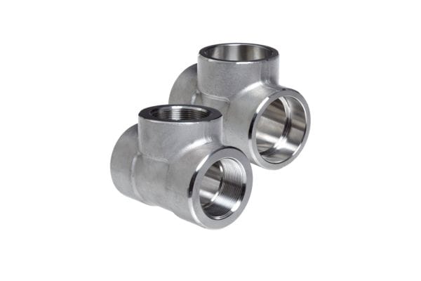
Socket weld fittings are a type of pipe fitting used to join sections of pipe by inserting one pipe into the socket end of a fitting, such as an elbow, tee, or coupling, and then applying a weld around the circumference of the joint. This method is commonly used in small-diameter piping systems, typically for pipes with diameters of 2 inches or less. The socket weld process results in a fillet weld, which provides a strong and reliable joint that is capable of withstanding moderate to high pressure.

Construction and Design Features:

Socket weld fittings are designed with a socket or recess at one end into which the pipe is inserted. The socket provides a snug fit, which ensures proper alignment and positioning of the pipe before welding. This design feature makes socket weld fittings particularly suitable for applications where precision and leak-tightness are critical.

The construction of socket weld fittings includes a flat face on the socket end, which comes into contact with the pipe’s end. This ensures that the pipe is seated correctly within the fitting, reducing the likelihood of misalignment during welding. The pipe is typically inserted until it bottoms out in the socket, then slightly withdrawn to provide an expansion gap. This gap allows for thermal expansion of the pipe during welding, reducing stress on the joint and ensuring a more secure connection.

Socket weld fittings are commonly made from materials such as stainless steel, carbon steel, and various alloys, depending on the application and the properties required, such as corrosion resistance, strength, or temperature tolerance.

Socket Weld Fittings

B. Installation Process

Preparation:

Begin by selecting the appropriate socket weld fitting for your application, ensuring it is compatible with the pipe material and size.

Inspect the pipe ends and fitting socket for cleanliness. Remove any dirt, grease, or other contaminants that could interfere with the welding process.

Measure and mark the pipe to ensure it is inserted to the correct depth in the socket.

Cutting and Deburring:

Cut the pipe to the desired length using a pipe cutter or saw. Ensure the cut is square to provide a proper fit within the socket.

Deburr the cut edges of the pipe to remove any sharp edges or burrs that could cause misalignment or disrupt the welding process.

Insertion:

Insert the pipe into the socket of the fitting until it bottoms out. Then, withdraw the pipe slightly to create a small expansion gap (typically around 1/16 inch). This gap allows for thermal expansion during welding.

Alignment:

Ensure the pipe and fitting are properly aligned before welding. Misalignment can cause weak joints and may lead to failure under pressure.

Tack Welding:

Perform tack welds at multiple points around the joint to hold the pipe and fitting in place. Tack welding helps maintain alignment during the final welding process.

Final Welding:

Complete the weld around the circumference of the joint. Use a fillet weld technique, applying consistent heat and filler material to ensure a strong, uniform weld.

Allow the weld to cool slowly to avoid thermal shock, which can lead to cracking.

C. Advantages of Socket Weld Fittings

Simplicity and Ease of Installation: One of the most significant advantages of socket weld fittings is their simplicity and ease of installation. The socket design allows for quick and accurate alignment of the pipe and fitting, reducing the need for complex jigs or fixtures. This ease of installation makes socket weld fittings ideal for small-bore piping systems, where precise alignment is critical but space may be limited.

Reduced Risk of Leakage in Small-Bore Pipes: Socket weld fittings are particularly well-suited for small-bore piping systems, where the risk of leakage is a primary concern. The fillet weld applied around the joint creates a strong, leak-tight seal that can withstand moderate to high pressures. Additionally, because the pipe is inserted into the socket before welding, there is less likelihood of misalignment or gaps that could lead to leaks.

Strength and Reliability: The fillet weld used in socket weld fittings provides a robust and reliable joint that can handle moderate pressures and vibrations. This makes socket weld fittings a popular choice for applications such as steam systems, chemical lines, and gas pipelines, where the integrity of the piping system is crucial.

D. Disadvantages of Socket Weld Fittings

Limitations in Larger Diameter and High-Pressure Applications: While socket weld fittings are ideal for small-bore piping systems, they are not well-suited for larger diameter pipes or high-pressure applications. The design of the socket weld creates a small protrusion inside the pipe, which can cause turbulence and reduce the flow rate in larger pipes. Additionally, the fillet weld may not be strong enough to withstand the stresses and pressures encountered in larger or high-pressure systems.

Potential for Stress Concentration and Corrosion: The design of socket weld fittings can lead to stress concentration at the joint, particularly if the expansion gap is not properly maintained during installation. Over time, this stress concentration can lead to cracking or failure of the joint. Additionally, the small gap between the pipe and the socket can trap moisture, chemicals, or debris, leading to crevice corrosion. This type of corrosion can be difficult to detect and may compromise the integrity of the piping system.

Butt Weld Fittings

A. What Are Butt Weld Fittings?

Butt weld fittings are a type of pipe fitting that joins two sections of pipe end-to-end through a welding process. These fittings are designed to create a strong, seamless joint that can withstand high pressures, temperatures, and corrosive environments. Unlike socket weld fittings, which involve inserting one pipe into a socket, butt weld fittings require the pipes to be aligned directly against each other, with their ends prepared for welding by beveling.

Construction and Design Features:

Butt weld fittings are constructed to provide a continuous metal structure that is as strong as or stronger than the pipes being connected. The process typically involves beveling the ends of the pipes or fittings to create a V-shaped groove, which allows for deeper penetration of the weld material. This deep penetration ensures a robust and durable joint that can handle high-stress conditions.

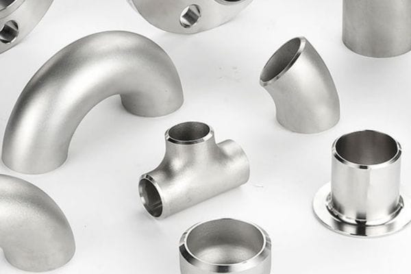
The design of butt weld fittings includes various shapes and sizes to accommodate different piping system requirements. Common types of butt weld fittings include elbows (for changing the direction of the pipe), tees (for branching the flow), reducers (for changing pipe diameter), and caps (for sealing the end of a pipe). These fittings are typically made from materials such as carbon steel, stainless steel, alloy steel, and other specialized materials, depending on the application’s requirements.

Butt Weld Fittings

B. Installation Process

Preparation:

Select the appropriate butt weld fitting for your application, ensuring compatibility with the pipe material and size.

Inspect the pipe ends and the fitting for cleanliness. Remove any dirt, grease, or contaminants that could interfere with the welding process.

Bevel the pipe ends if they are not pre-beveled. The beveling process creates a V-shaped groove that allows for proper weld penetration.

Alignment:

Align the pipes or fittings end-to-end, ensuring that the bevels match up perfectly. Misalignment can lead to weak joints and potential failure under pressure.

Use alignment tools such as clamps or jigs to hold the pipes and fittings in place during welding. Precision in alignment is crucial for a strong weld.

Tack Welding:

Perform tack welds at several points around the joint to hold the pipes and fittings in place. Tack welds are temporary welds that prevent movement during the final welding process.

Final Welding:

Complete the weld by filling the V-groove with welding material. This process typically involves multiple passes with the welding torch to ensure full penetration and strength.

Use appropriate welding techniques, such as TIG (Tungsten Inert Gas), MIG (Metal Inert Gas), or stick welding, depending on the material and application requirements.

Allow the weld to cool gradually to prevent thermal shock, which can lead to cracking.

Inspection and Testing:

After welding, inspect the joint visually and, if necessary, use non-destructive testing methods such as radiography, ultrasonic testing, or dye penetrant inspection to ensure the weld’s integrity.

Perform pressure testing on the system to confirm that the joint can withstand the operational conditions without leaking.

C. Advantages of Butt Weld Fittings

Superior Strength and Durability: One of the primary advantages of butt weld fittings is their superior strength and durability. The full penetration weld created during installation provides a joint that is as strong as the pipe itself, if not stronger. This makes butt weld fittings ideal for high-pressure and high-temperature applications where joint integrity is critical. The continuous, homogeneous weld ensures that the joint can withstand significant mechanical stress, thermal expansion, and contraction, as well as the corrosive effects of harsh chemicals or fluids.

Seamless and Smooth Interior, Reducing Friction and Turbulence: Butt weld fittings create a seamless interior surface within the piping system, which is particularly beneficial for fluid dynamics. The absence of internal ridges or gaps reduces friction and turbulence, allowing for a smoother flow of liquids or gases. This characteristic is especially important in industries where maintaining efficient flow rates and minimizing pressure drops are crucial, such as in chemical processing or oil and gas transportation. Additionally, the smooth interior reduces the risk of buildup or blockage, contributing to the system’s long-term reliability.

D. Disadvantages of Butt Weld Fittings

Higher Cost and Complexity of Installation: One of the main disadvantages of butt weld fittings is the higher cost associated with their installation. The process requires skilled labor, specialized tools, and precision alignment, all of which contribute to increased labor costs. Additionally, the welding process for butt weld fittings is more time-consuming than for other types of fittings, such as socket welds or threaded fittings. The need for beveling, alignment, and multiple welding passes adds to the overall complexity and cost of installation.

Need for Precise Alignment and Skilled Labor: Installing butt weld fittings requires a high degree of precision in alignment and welding. Any misalignment or poor welding technique can compromise the strength of the joint, leading to potential failures. As a result, the installation of butt weld fittings must be carried out by skilled welders who are trained to meet industry standards. This requirement for skilled labor can limit the use of butt weld fittings in situations where such expertise is not readily available.

Conclusion

When deciding between socket weld and butt weld fittings, it is crucial to carefully evaluate your specific project requirements, including the size of the piping system, operating pressures, temperatures, and budget constraints. Each fitting type has its own set of advantages and limitations, and the best choice depends on the unique demands of your application. By understanding these differences, you can make an informed decision that ensures the long-term performance and reliability of your piping system.


FAQ

What is the main difference between socket weld and butt weld fittings?

Socket weld fittings involve inserting a pipe into a socket before welding, while butt weld fittings join pipes end-to-end with a full penetration weld.

Which type of fitting is better for high-pressure applications?

Butt weld fittings are generally better suited for high-pressure applications due to their superior strength and seamless joint.

Are socket weld fittings suitable for large-diameter pipes?

No, socket weld fittings are typically used for small-diameter pipes (usually under 2 inches) and are not ideal for large-diameter applications.

Do butt weld fittings require special tools for installation?

Yes, butt weld fittings require tools for pipe beveling, precise alignment, and advanced welding techniques, often necessitating skilled labor.

Which fitting type is easier to install?

Socket weld fittings are easier and quicker to install, making them a cost-effective option for small-bore piping systems.

Can I inspect socket and butt weld fittings easily?

Socket weld fittings are generally easier to inspect visually, while butt weld fittings may require non-destructive testing methods like radiography for thorough inspection.

Reassembling Hydraulic Fittings banner

Reassembling Hydraulic Fittings: How Many Times is Safe?

Did you know that a significant percentage of hydraulic system failures can be traced back to improper reassembly of fittings? Studies suggest that up to 30% of hydraulic leaks are due to issues related to reassembling fittings, leading to costly downtime and potential safety hazards. This statistic underscores a critical question: How many times can you safely reassemble a hydraulic fitting before it becomes a liability?

Understanding Hydraulic Fittings

Types of Hydraulic Fittings

JIC Fittings:

JIC fittings are widely used due to their reliable, high-pressure capabilities. They feature a 37-degree flare seating surface that forms a strong seal when the fitting is tightened. JIC fittings are versatile, and commonly found in fluid power systems across many industries, including agriculture, automotive, and industrial machinery.

BSP Fittings:

BSP fittings are prevalent in Europe and the UK, offering a threaded connection that can be either tapered (BSPT) or parallel (BSPP). These fittings are known for their robust sealing properties, especially when paired with an O-ring or bonded seal, making them ideal for applications where pressure integrity is critical.

ORFS Fittings:

ORFS fittings provide a reliable, leak-free connection by utilizing an O-ring embedded in the face of the fitting. These are particularly useful in applications where vibration or thermal cycling might otherwise cause fittings to loosen, such as in heavy equipment or hydraulic power units.

Face Seal Fittings:

Face seal fittings, such as SAE Straight Thread O-Ring Boss (ORB), offer a leak-proof connection ideal for high-pressure applications. They rely on an O-ring seated in a groove to create a tight seal, minimizing the risk of fluid leaks even under extreme conditions.

hydraulic adapters manufacturer Topa in China

Materials Used in Manufacturing Fittings

The material composition of hydraulic fittings plays a crucial role in their performance, durability, and suitability for specific applications. Common materials include:

Steel:

Steel fittings are strong, durable, and capable of withstanding high pressures. They are commonly used in industrial and heavy machinery applications. However, they can be susceptible to corrosion, which is why they are often coated with zinc or other protective finishes.

Stainless Steel:

Stainless steel fittings offer superior corrosion resistance, making them ideal for applications in harsh environments, such as marine, chemical processing, or food and beverage industries. While more expensive than regular steel, their longevity and performance in corrosive environments justify the cost.

Brass:

Brass fittings are commonly used in lower-pressure applications, particularly in industries like plumbing, where their resistance to corrosion from water is advantageous. They are also easier to machine, which makes them a cost-effective option for certain applications.

Aluminum:

Aluminum fittings are lightweight and corrosion-resistant, often used in aerospace and automotive applications where weight reduction is crucial. However, they are not as strong as steel or stainless steel, limiting their use in high-pressure systems.

Function and Role in Hydraulic Systems

How Fittings Contribute to System Integrity:

Hydraulic fittings are the connectors that link hoses, pipes, and tubes within a hydraulic system. They play a critical role in maintaining the system’s integrity by ensuring a leak-free, secure connection that can withstand the pressures and temperatures generated by the hydraulic fluid. The effectiveness of a hydraulic system depends on the reliability of these fittings, as even a minor leak can lead to significant system inefficiencies, contamination, or failure.

The design of hydraulic fittings, including their threading, sealing surfaces, and materials, is tailored to specific pressure ranges and fluid types. This specificity helps prevent issues such as fluid loss, pressure drops, or fitting blowouts, which can have catastrophic consequences in high-stakes environments like manufacturing plants or aircraft systems.

Importance of Proper Installation and Assembly:

The installation and assembly of hydraulic fittings are just as critical as their selection. Proper installation ensures that the fitting is seated correctly, with appropriate torque applied to create a secure, leak-free connection. Misalignment, over-tightening, or under-tightening during assembly can lead to compromised seals, resulting in leaks or fitting failure under pressure.

Additionally, the use of appropriate tools and adherence to manufacturer guidelines during installation cannot be overstated. For instance, using a torque wrench ensures that the fitting is neither too loose, risking leaks, nor too tight, which could damage the fitting or the connected component.

The Reassembly Process Explained

What is Reassembly?

Reassembly of hydraulic fittings refers to the process of disassembling and then reassembling the components of a hydraulic fitting to restore or maintain the integrity of the hydraulic system. Reassembly is often required during routine maintenance, repairs, or when modifications to the hydraulic system are necessary. Common scenarios include replacing worn-out seals, adjusting hose lengths, or reconfiguring connections to accommodate system changes.

Reassembly is crucial in ensuring that the hydraulic system continues to operate efficiently and without leaks. However, the process requires careful attention to detail, as improper reassembly can lead to compromised fitting integrity, resulting in leaks, reduced performance, or even system failure.

Steps Involved in Reassembling Hydraulic Fittings

Preparation:

Gather Tools and Equipment: Before beginning, ensure you have the appropriate tools for disassembly and reassembly, such as wrenches, torque tools, and lubricant if required.

Depressurize the System: Always start by depressurizing the hydraulic system to prevent fluid spray or injury. Disconnect the system from its power source and ensure all pressure has been safely released.

Disassembly:

Loosen the Fitting: Using the appropriate wrench, carefully loosen the fitting by turning it counterclockwise. Avoid applying excessive force that could damage the threads.

Remove the Fitting Components: Once loosened, gently separate the fitting components, including the body, nut, and any seals or O-rings.

Inspect the Components: Examine each component for signs of wear, damage, or corrosion. Replace any parts that show signs of deterioration.

Preparation for Reassembly:

Clean the Components: Thoroughly clean all fitting components to remove any dirt, debris, or old lubricant. This ensures a proper seal and prevents contamination of the hydraulic fluid.

Lubricate Threads and Seals: Apply a small amount of hydraulic fitting lubricant to the threads and seals, if recommended by the manufacturer. This helps achieve the correct torque during reassembly and reduces the risk of galling (thread damage).

Hydraulic Bulkhead Fittings installation

Reassembly:

Reposition the Components: Carefully place the fitting components back in their original positions. Ensure that any seals or O-rings are seated correctly and that the threads are aligned.

Tighten the Fitting: Using a wrench, tighten the fitting by turning it clockwise. Follow the manufacturer’s recommended torque specifications to avoid overtightening or under-tightening. If using a torque wrench, ensure it is calibrated correctly.

Testing:

Check for Leaks: Once reassembly is complete, gradually reintroduce pressure to the system while monitoring the fitting for any signs of leakage.

Final Adjustments: If necessary, make minor adjustments to the fitting to achieve a leak-free connection. Recheck the torque if adjustments are made.

Common Mistakes During Reassembly

Overtightening:

Overapplying torque to a hydraulic fitting can damage the threads, crush seals, and distort the fitting body. This not only compromises the seal but can also lead to premature failure of the fitting.

Improper Alignment:

Misalignment of the fitting components during reassembly is a common mistake that can lead to cross-threading. Cross-threading damages both the fitting and the connected component, making it difficult to achieve a secure seal and increasing the risk of leaks.

Reuse of Damaged Seals:

Reusing seals or O-rings that are worn, cracked, or deformed is a frequent error. Even minor imperfections in these components can prevent a proper seal, leading to fluid leaks and potential system failure.

Inadequate Cleaning:

Failing to thoroughly clean the fitting components before reassembly can introduce contaminants into the hydraulic system. Dirt, debris, or old lubricant can prevent a proper seal and cause wear on the system over time.

Incorrect Torque Application:

Using incorrect torque during reassembly—whether too little or too much—can lead to leaks or damage. It’s essential to follow the manufacturer’s guidelines precisely to ensure a secure and durable connection.

Factors Influencing Reassembly Limits

Material Wear and Tear

Steel:

Steel fittings are known for their strength and durability, making them capable of withstanding multiple reassemblies without significant wear. However, repeated reassembly can still cause minor thread deformation or galling, especially if proper lubrication is not used. Over time, these issues can compromise the seal, leading to leaks.

Stainless Steel:

Stainless steel is highly resistant to corrosion and wear, which can extend the number of times it can be reassembled. However, stainless steel is also prone to galling—a form of adhesive wear that occurs when metal surfaces slide against each other under pressure. To mitigate this, it’s essential to use proper lubricants and avoid overtightening during reassembly.

Brass:

Brass fittings are softer than steel or stainless steel, which makes them more susceptible to wear and deformation after multiple reassemblies. While brass is corrosion-resistant and easier to machine, repeated reassembly can quickly wear down the threads and sealing surfaces, reducing the fitting’s effectiveness over time.

Aluminum:

Aluminum fittings are lightweight and corrosion-resistant but also softer and more prone to wear than steel or stainless steel. After several reassemblies, aluminum fittings may show significant thread wear, making it difficult to achieve a reliable seal. Due to this, aluminum fittings generally have a lower reassembly tolerance and may need to be replaced more frequently.

material Topa China factory

Signs of Wear That Indicate a Fitting Should Not Be Reused

Recognizing the signs of wear on a hydraulic fitting is crucial for determining whether it’s safe to reassemble or if it should be replaced. Common indicators that a fitting should not be reused include:

Thread Damage:

Visible thread wear, such as rounding, flattening, or galling, suggests that the fitting may no longer create a secure seal. Damaged threads can also lead to cross-threading during reassembly, further compromising the fitting.

Deformed Seals or O-Rings:

Seals and O-rings that appear cracked, flattened, or hardened are no longer effective at preventing leaks. These components should be replaced rather than reused.

Corrosion:

Any signs of corrosion on the fitting, especially near the sealing surfaces or threads, indicate that the fitting’s integrity has been compromised. Corroded fittings are more likely to leak and should be replaced immediately.

Surface Cracks or Deformation:

Inspect the fitting body for any visible cracks or deformities. Even minor cracks can expand under pressure, leading to sudden fitting failure.

Type of Fitting

Compression Fittings:

Compression fittings rely on a compression ring or ferrule to create a seal. Repeated reassembly can cause the ferrule to deform, reducing its ability to seal effectively. Therefore, compression fittings generally have a lower reassembly tolerance, and the ferrule often needs to be replaced after a few reassemblies.

Flare Fittings:

Flare fittings use a cone-shaped end that flares out to fit against a corresponding surface. These fittings can generally withstand more reassemblies than compression fittings, as long as the flared surface remains undamaged. However, excessive reassembly can lead to metal fatigue in the flare, making it less effective at sealing.

O-Ring Face Seal (ORFS) Fittings:

ORFS fittings are designed for high-pressure applications and use an O-ring to create a leak-proof seal. While these fittings can typically be reassembled multiple times, the O-ring is a worn component that may need to be replaced with each reassembly to maintain a reliable seal.

Pipe Thread Fittings:

Pipe thread fittings rely on the threads themselves to create a seal, often with the addition of thread sealant or tape. Repeated reassembly can cause the threads to wear down, particularly in softer materials like brass or aluminum. The use of sealant can also make reassembly challenging, as residual sealant can cause improper seating of the threads.

Pressure and Temperature Conditions

How the Operational Environment Affects the Reusability of Fittings:

The operational conditions—particularly the pressure and temperature—under which a hydraulic fitting is used significantly impact its reusability. High-pressure environments place additional stress on fittings, particularly on the sealing surfaces and threads. Over time, this stress can lead to deformation, making the fitting less effective at sealing after multiple reassemblies.

High-Pressure Environments:

In systems operating under high pressure, the forces acting on the fittings are much greater, increasing the risk of thread wear and seal degradation during reassembly. Fittings in these environments may have a lower reassembly tolerance and require more frequent inspection and replacement.

Temperature Extremes:

Extreme temperatures—both high and low—can affect the materials used in hydraulic fittings. High temperatures can cause metal expansion and O-ring degradation, while low temperatures can make materials brittle. These effects can reduce the number of times a fitting can be safely reassembled, particularly if the fitting is repeatedly exposed to these conditions.

Vibration and Shock:

Fittings in environments with high vibration or shock loads are subject to additional wear during reassembly. Vibration can loosen connections over time, and repeated tightening can lead to over-torquing, which damages the fitting.

Application-Specific Considerations

Construction Industry:

In construction, hydraulic systems are often exposed to harsh environments, including dirt, dust, and extreme weather conditions. Fittings in these systems may require more frequent reassembly due to maintenance needs, but the harsh conditions also increase wear, limiting the number of safe reassemblies.

Manufacturing Industry:

In manufacturing, hydraulic systems are typically operated in controlled environments. Fittings may not need to be reassembled as frequently, and when they are, the controlled conditions help extend the reassembly limit. However, the precision required in manufacturing systems means that even slight wear can necessitate replacement rather than reassembly.

Aerospace Industry:

The aerospace industry has extremely stringent requirements for hydraulic fittings, with a focus on reliability and safety. Fittings in aerospace applications may have very low reassembly limits, as the risk associated with failure is too high. In many cases, fittings are replaced rather than reassembled to ensure maximum reliability.

Agricultural Industry:

Agricultural machinery often operates in environments with high levels of dirt, debris, and moisture. Fittings in these systems may be subject to frequent disassembly for cleaning and maintenance, which can limit their reassembly lifespan. The combination of harsh environmental conditions and frequent maintenance cycles means that fittings in agriculture may require more regular replacement.

Risks Associated with Repeated Reassembly

Potential for Leaks

How Reassembly Can Affect the Seal and Lead to Leaks:

One of the most significant risks associated with repeated reassembly of hydraulic fittings is the potential for leaks. Each time a fitting is reassembled, there is a chance that the seal will be compromised, especially if the fitting is not handled with care or if the components have started to wear.

During reassembly, the threads, seals, and seating surfaces are subjected to mechanical stress. Over time, this stress can cause subtle deformations in the threads or flattening of the O-rings and seals, leading to an imperfect fit. Even a minor imperfection can result in fluid leaks, which are particularly problematic in high-pressure hydraulic systems where even small leaks can lead to significant fluid loss and pressure drops.

Moreover, the use of improper torque during reassembly—either too much or too little—can exacerbate this issue. Overtightening can crush seals and damage threads, while under-tightening may not provide a sufficient seal, both leading to potential leaks.

Reduced Fitting Reliability

The Impact on Performance and Safety:

Repeated reassembly does not just increase the risk of leaks; it can also reduce the overall reliability of the hydraulic fitting. Hydraulic fittings are designed to create a secure and leak-proof connection under specific conditions. Each reassembly weakens the fitting’s ability to maintain this connection, particularly if the fitting has already experienced wear and tear.

Reduced reliability manifests in several ways:

Loss of Structural Integrity: The threads and seals may not engage as tightly as they did during the initial assembly, leading to a less secure connection that is more susceptible to loosening under pressure or vibration.

Inconsistent Performance: A fitting that has been reassembled multiple times may no longer maintain consistent pressure levels within the system, leading to fluctuations in system performance and efficiency.

Safety Hazards: In critical applications, such as in aerospace or industrial machinery, reduced fitting reliability can pose significant safety risks. A sudden fitting failure can lead to system shutdowns, fluid spills, or even catastrophic accidents, especially if the system is operating under high pressure.

Conclusion

To maintain the integrity and reliability of your hydraulic systems, make it a routine to inspect your fittings regularly and follow best practices for reassembly. Don’t wait for a failure to occur—be proactive in replacing worn or damaged fittings. By doing so, you can prevent leaks, avoid costly downtime, and ensure the safety of your operations. Remember, the key to a long-lasting hydraulic system lies in attention to detail and a commitment to quality maintenance practices.


FAQ

How many times can I reassemble a hydraulic fitting?

The number of times a hydraulic fitting can be safely reassembled depends on the material, type of fitting, and the conditions under which it operates. Regular inspections are crucial to determine if a fitting is still suitable for reuse.

What are the signs that a hydraulic fitting should not be reused?

Signs include visible thread damage, deformed or cracked seals, corrosion, and any surface cracks or deformations in the fitting body.

Can I reuse the same O-ring when reassembling a fitting?

It’s generally recommended to replace the O-ring each time a fitting is reassembled to ensure a reliable seal and prevent leaks.

What happens if I overtighten a hydraulic fitting during reassembly?

Overtightening can damage the threads, crush seals, and lead to leaks or fitting failure. Always use the recommended torque specifications.

Is it safe to reassemble hydraulic fittings in high-pressure systems?

Reassembly in high-pressure systems should be done with caution. Fittings in these environments are under greater stress, and repeated reassembly can increase the risk of failure. Inspect carefully and replace fittings as needed.

How can I prevent leaks when reassembling hydraulic fittings?

Ensure that all components are clean, and properly aligned and that the correct torque is applied. Replace any worn or damaged parts, including seals, to maintain a secure, leak-free connection.

NPT vs NPS Threads banner

NPT vs NPS Threads: Are They Compatible?

NPT (National Pipe Tapered) and NPS (National Pipe Straight) threads are two of the most commonly used thread standards in various industries. NPT threads, known for their tapered design, are widely used in applications where a secure, leak-proof seal is necessary. On the other hand, NPS threads feature a straight design and are often used in situations where a tight seal is achieved through other means, such as gaskets or O-rings. Both thread types are essential in many sectors, but their differences can lead to significant challenges if not properly understood.

Understanding NPT Threads

A. Definition and Characteristics

NPT threads are one of the most widely used thread standards in North America. They are defined by their tapered thread design, where the diameter of the threads decreases along the length of the fitting. This taper creates a wedging action when the male and female threads are tightened together, allowing for a secure and leak-resistant connection. NPT threads are typically used in applications where a tight seal is critical, such as in fluid and gas systems. The sealing is primarily achieved through the metal-to-metal contact between the threads, which is further enhanced by the use of sealing compounds like Teflon tape or pipe dope to prevent leaks.

B. Applications of NPT Threads

NPT threads are commonly found in a wide range of applications due to their reliability and effectiveness in creating leak-proof connections. Some of the most common uses include:

Plumbing Systems: NPT threads are extensively used in residential, commercial, and industrial plumbing for connecting pipes and fittings that carry water, sewage, and other fluids.

Gas Lines: The secure sealing properties of NPT threads make them ideal for gas lines, where preventing leaks is paramount for safety.

Hydraulic Systems: In hydraulic applications, NPT threads are often used to connect hoses, pipes, and valves, ensuring that high-pressure fluids are contained within the system.

Oil and Gas Industry: NPT threads are prevalent in the oil and gas industry, where they are used in pipelines, drilling equipment, and various other components that require durable and leak-resistant connections.

NPT Fitting drawing Topa

C. Advantages of NPT Threads

NPT threads offer several advantages that contribute to their widespread use:

Reliable Sealing: The tapered design of NPT threads creates a mechanical seal that is effective in preventing leaks, especially when combined with appropriate sealing compounds.

Ease of Use: NPT threads are relatively easy to install and do not require complex tools or techniques, making them a convenient choice for various applications.

Versatility: NPT threads are compatible with a wide range of materials, including steel, brass, copper, and plastic, allowing them to be used in diverse environments and systems.

Cost-Effective: NPT threads are a cost-effective solution for creating secure connections in many industrial and plumbing applications, reducing the need for more expensive alternatives.

D. Limitations of NPT Threads

Despite their many benefits, NPT threads have some limitations that must be considered:

Need for Sealing Compounds: While the tapered design provides a good mechanical seal, NPT threads often require additional sealing compounds, such as Teflon tape or pipe dope, to ensure a completely leak-proof connection. This adds an extra step in the installation process and can be a potential source of error if not applied correctly.

Risk of Over-Tightening: Over-tightening NPT threads can lead to deformation of the threads, compromising the seal and potentially causing leaks. It also increases the risk of damaging the fittings, which can lead to costly repairs or replacements.

Thread Wear: With repeated use, NPT threads can wear down, reducing their effectiveness in creating a seal. This wear and tear can lead to leaks over time, especially in high-pressure or high-vibration environments.

Limited Reusability: Due to the taper and the need for sealing compounds, NPT threads may not be easily reusable after disassembly, as the threads can be damaged or the sealing compound may not be effective when reapplied.

Understanding NPS Threads

A. Definition and Characteristics

NPS threads are a type of thread standard characterized by a straight thread design, meaning the diameter of the threads remains constant along the length of the fitting. Unlike NPT (National Pipe Tapered) threads, NPS threads do not taper and therefore do not create a seal through thread wedging. Because of this, NPS threads do not inherently provide a leak-proof seal when used alone. Instead, they rely on the use of gaskets, O-rings, or other sealing mechanisms to create a secure and leak-resistant connection. NPS threads are often chosen for applications where precise alignment is necessary or where the connection does not require a pressure-tight seal.

B. Applications of NPS Threads

NPS threads are commonly used in a variety of applications where the primary concern is not creating a pressure-tight seal, but rather ensuring proper alignment and connection between components. Some typical applications include:

Mechanical Joints: In situations where components need to be securely joined without the requirement for a leak-proof seal, NPS threads are often used. These threads allow for the accurate alignment of parts, which is critical in many mechanical assemblies.

Electrical Conduits: NPS threads are frequently used in electrical conduit systems, where the primary function is to provide a secure connection for the conduits rather than to seal against fluid or gas leaks.

Pipe Hangers and Supports: NPS threads are used in pipe hangers and supports, where the emphasis is on holding pipes in place rather than preventing leaks.

Low-Pressure Fluid Systems: In applications where the fluid pressure is low and the risk of leakage is minimal, NPS threads may be used with additional sealing methods like gaskets.

measure NPS Threads

C. Advantages of NPS Threads

NPS threads offer several advantages, particularly in situations where precise alignment and ease of assembly are important:

Ease of Alignment: The straight design of NPS threads allows for easy and precise alignment of components, making them ideal for applications where the accurate positioning of parts is critical.

Simplicity in Non-Pressure Applications: NPS threads are well-suited for non-pressure applications where sealing is not the primary concern, reducing the need for complex sealing techniques.

Compatibility with Sealing Mechanisms: While NPS threads do not seal on their own, they are compatible with a variety of sealing mechanisms, such as gaskets or O-rings, which can be easily added to create a leak-proof connection.

Less Susceptibility to Over-Tightening: Because NPS threads do not rely on tapering to create a seal, there is less risk of over-tightening, which can lead to thread deformation and connection failure in tapered threads.

D. Limitations of NPS Threads

Despite their advantages, NPS threads also have certain limitations that must be considered in their use:

Need for Additional Sealing Methods: Unlike NPT threads, NPS threads do not create a seal through the threads themselves. This means that additional sealing methods, such as gaskets or O-rings, are required to achieve a leak-proof connection. This can complicate the installation process and increase the potential for leaks if the sealing components are not properly installed.

Limited Use in High-Pressure Applications: Due to their reliance on external sealing methods, NPS threads are generally not suitable for high-pressure applications where a strong, self-sealing connection is necessary.

Potential for Misapplication: If NPS threads are mistakenly used in situations requiring a pressure-tight seal without the proper sealing methods, the result could be leaks, system failures, or safety hazards.

Incompatibility with Some Threaded Fittings: NPS threads are not always compatible with other types of threaded fittings, particularly those that are tapered, which can limit their use in certain applications.

Key Differences Between NPT and NPS Threads

A. Tapered vs Straight Threads

One of the most fundamental differences between NPT and NPS threads is their design:

Tapered Threads (NPT): NPT threads have a tapered design, meaning the thread diameter decreases gradually along the length of the fitting. This taper creates a wedging effect when the male and female threads are tightened together, which helps to form a tight seal. The taper allows the threads to bind together, creating pressure that enhances the sealing capability without the need for additional sealing materials in many cases. This design is particularly beneficial in high-pressure applications where maintaining a leak-proof connection is critical.

Straight Threads (NPS): NPS threads, on the other hand, have a straight design, where the thread diameter remains constant throughout the fitting’s length. Unlike tapered threads, NPS threads do not create a natural seal when tightened. Instead, they rely on other means, such as gaskets, O-rings, or thread sealants, to create a leak-proof connection. This makes NPS threads more suitable for applications where the precise alignment of components is essential, rather than sealing against high pressure.

NPTF vs NPSM

B. Sealing Mechanism

The difference in thread design between NPT and NPS threads leads to distinct sealing mechanisms:

NPT Threads (Sealing Through Wedging): NPT threads achieve a seal through the mechanical wedging of the threads as they are tightened. The tapered design causes the threads to bind together more tightly as they are screwed in, which compresses the material and creates a seal. In many cases, this mechanical seal is sufficient to prevent leaks, although sealants such as Teflon tape or pipe dope are often used to enhance the seal, especially in high-pressure or critical applications.

NPS Threads (Requiring Additional Sealing Methods): NPS threads do not create a seal through the threads alone because of their straight design. To achieve a leak-proof connection, NPS threads require the use of additional sealing methods. Common sealing methods include:

Gaskets or O-rings: These are placed between the mating surfaces to prevent leaks.

Thread Sealants: Such as Teflon tape or pipe dope, are applied to the threads to fill any gaps and ensure a tight seal.

Mechanical Seals: In some cases, the seal is achieved through a mechanical face-to-face connection, where the threads only serve to hold the components in place.

C. Thread Specifications and Standards

NPT and NPS threads are governed by different technical specifications and standards, which define their dimensions, tolerances, and applications:

NPT Threads (ANSI/ASME B1.20.1): The standards for NPT threads are outlined in the ANSI/ASME B1.20.1 specification. This standard defines the dimensions, thread angle, pitch, and taper rate for NPT threads, ensuring consistency and compatibility across different fittings and applications. The taper rate for NPT threads is 1/16 inch per inch, which is crucial for achieving the wedging action that creates the seal.

NPS Threads (ANSI/ASME B1.20.1): While NPS threads share the same standard as NPT threads (ANSI/ASME B1.20.1), they differ in the lack of taper. NPS threads are straight and follow the same pitch and thread angle specifications as NPT but without the taper. This means that while they may appear similar, NPS threads will not create a seal on their own and must adhere to specific sealing practices outlined in industry standards.

Compatibility of NPT and NPS Threads

A. Thread Engagement

NPT and NPS threads can physically engage with each other due to their shared thread pitch and diameter, which allows the threads to be screwed together. However, the key difference lies in the taper of NPT threads versus the straight design of NPS threads:

Engagement Process: When an NPT male fitting is threaded into an NPS female fitting, the threads will engage initially, as the pitch and thread angle are compatible. However, as the NPT threads taper, they will only contact the NPS threads at a few points rather than along the entire length of the thread, leading to a less secure and uneven fit.

Partial Engagement: The engagement between NPT and NPS threads is often partial and inconsistent, resulting in gaps that can compromise the connection’s integrity. This partial engagement can lead to misalignment and difficulty in achieving the desired torque, further complicating the connection.

B. Sealing Issues

The most significant challenge when using NPT and NPS threads together is achieving a proper seal:

Lack of Wedging Effect: NPT threads rely on their tapered design to create a mechanical seal through wedging, while NPS threads do not taper. When combined, the NPT threads cannot fully wedge into the NPS threads, leading to an incomplete seal. The mismatch between the taper and straight design creates gaps that are difficult to seal, especially in high-pressure applications.

Dependence on Sealants: While thread sealants like Teflon tape or pipe dope can be used to fill the gaps and prevent leaks, they are often not sufficient to overcome the fundamental differences in thread design. The reliance on sealants increases the likelihood of improper installation, where insufficient or uneven application can result in leaks.

Inconsistent Sealing: Even with the use of sealing compounds, inconsistent thread engagement can lead to areas where the sealant is not fully effective. This inconsistency increases the risk of leaks over time, especially under conditions of vibration, temperature fluctuations, or pressure changes.

C. Risks of Using NPT and NPS Together

Using NPT and NPS threads together without fully understanding the implications can lead to several significant risks:

Leaks: The most immediate risk is fluid or gas leakage due to the inability to create a proper seal between the NPT and NPS threads. Leaks can occur gradually or suddenly, depending on the application’s pressure and environmental conditions, potentially leading to hazardous situations.

Safety Hazards: In systems that handle flammable, toxic, or high-pressure fluids and gases, leaks caused by improper thread compatibility can result in severe safety hazards, including fire, explosion, or exposure to harmful substances. These risks are particularly high in industrial settings where the consequences of a leak can be catastrophic.

System Failures: Over time, the incomplete seal and uneven engagement can cause stress on the threaded connection, leading to fatigue and eventual failure. In critical systems, such as hydraulic lines or gas pipelines, a failure can result in significant operational disruptions, costly repairs, and potential environmental damage.

How to Choose the Right Thread Type?

Selecting the appropriate thread type is essential to ensuring system integrity, performance, and safety. Misapplication can lead to leaks, equipment failure, and even hazardous incidents in high-pressure environments. Below are practical guidelines based on common application scenarios:

A. For High-Pressure Sealing Systems → Choose NPT

If your system involves high-pressure fluids or gases—such as in hydraulic systems, fuel pipelines, or gas lines—NPT (National Pipe Tapered) threads are the preferred choice.

Why NPT Works: Its tapered design allows for a mechanical seal as the male and female threads wedge tightly together.

Sealing Enhancements: Use Teflon tape or pipe dope (thread sealant) to fill micro gaps and ensure a leak-proof connection.

Recommended For:

Oil & gas pipelines

Compressed air systems

Water supply lines under pressure

⚠️ Be cautious not to over-tighten, as it may deform the threads and compromise the seal.

NPS to NPT

B. For Precise Alignment Without Sealing Needs → Choose NPS

In applications where a leak-proof seal is not essential, but precise orientation or alignment of components is critical—NPS (National Pipe Straight) threads are better suited.

Why NPS Works: The straight thread design allows components to align accurately without binding, which is beneficial for certain mechanical or structural connections.

Sealing Required: Always use gaskets, O-rings, or flange face seals to achieve any level of fluid or gas containment.

Recommended For:

Electrical conduit fittings

Structural pipe supports

Decorative or architectural piping

⚠️Use thread sealants only if sealing is required and appropriate for the connection design.

C. Avoid Mixing NPT and NPS Threads

Although NPT and NPS threads may share the same pitch and thread angle, they are not functionally compatible due to their difference in shape (tapered vs. straight).

Risks of Mixing:

Incomplete thread engagement

Poor sealing and potential for leaks

Increased likelihood of thread damage

Only Mix If:

Specifically engineered and approved by the manufacturer

Successfully pressure-tested under operating conditions

⚠️ Never assume compatibility based on visual similarity. Thread mismatches are a common cause of failure in pressure systems.

Conclusion

As you move forward with your projects, take the time to carefully consider the compatibility of the threads you choose. Whether you’re working on a small plumbing repair or managing a large industrial system, selecting the right thread type is essential for ensuring a safe and effective connection. If you’re unsure about which threads to use, or if you’re dealing with a critical application, don’t hesitate to seek professional advice. Proper thread selection and installation can prevent costly mistakes, enhance system performance, and most importantly, ensure the safety and reliability of your operations.


FAQ

What is the main difference between NPT vs NPS threads?

NPT threads are tapered, creating a seal through wedging, while NPS threads are straight and require additional sealing methods like gaskets or O-rings.

Can NPT and NPS threads be used together?

While NPT and NPS threads can physically engage, they are not recommended to be used together for sealing purposes, as they cannot create a reliable seal on their own.

What applications are NPT threads best suited for?

NPT threads are ideal for applications requiring leak-proof seals, such as plumbing, gas lines, and hydraulic systems.

In what situations should I use NPS threads?

NPS threads are best for applications where precise alignment is necessary, or where sealing is achieved through other means, such as in mechanical joints or electrical conduits.

What are the risks of mixing NPT and NPS threads?

Mixing NPT and NPS threads can lead to leaks, safety hazards, and potential system failures due to their inability to form a proper seal together.

Do NPS threads require sealant?

Yes, NPS threads typically require sealants or gaskets to achieve a leak-proof connection, as they do not seal on their own.

Why Proper Hydraulic Hose Assembly Sizing is Crucial banner

Why Proper Hydraulic Hose Assembly Sizing is Crucial

Did you know that nearly 30% of hydraulic hose failures are directly linked to improper sizing? This startling statistic underscores a critical issue in hydraulic systems that can lead to significant downtime and costly repairs. Proper sizing of hydraulic hose assemblies is crucial to ensure system efficiency, safety, and longevity. Incorrectly sized hoses can lead to leaks, reduced performance, and even catastrophic failures, making it essential for businesses to understand and implement correct sizing practices.

Understanding Hydraulic Hose Assemblies

Hydraulic hose assemblies are integral components of hydraulic systems that transmit hydraulic fluid between various parts of the system. They consist of hoses, fittings, and couplings designed to handle high-pressure fluids safely and efficiently.

Components

Hose: The flexible tube that carries the hydraulic fluid. It is typically reinforced with layers of synthetic fibers or steel wire to withstand pressure.

Fittings: Connectors that attach the hose to other components in the system, such as pumps, valves, or cylinders.

Couplings: Devices that secure the fittings to the hose, ensuring a leak-proof connection.

Ferrules: Metal bands that crimp around the hose and fitting to provide a secure attachment.

High Pressure Hose Assembly Failure

Different Types of Hydraulic Hoses and Their Applications

General Purpose Hoses: Suitable for a wide range of applications including low to moderate pressure hydraulic systems.

High Pressure Hoses: Designed for high-pressure applications, often used in heavy machinery and industrial equipment.

Reinforced Hoses: Featuring multiple layers of reinforcement to handle extreme pressures and harsh conditions, commonly used in construction and mining.

Thermoplastic Hoses: Made from synthetic materials, these hoses are used in applications requiring flexibility and resistance to various chemicals.

Rubber Hoses: Flexible and durable, used in a range of hydraulic systems for their resistance to abrasion and impact.

Basic Principles of Hydraulic Systems and the Role of Hose Assemblies

Hydraulic Systems Principles:

Fluid Power: Hydraulic systems use pressurized fluid to transmit power. The fluid is typically oil, which is pressurized by a pump and directed through various components.

Pressure and Flow: The system operates based on the principles of fluid pressure and flow. Pressure drives the fluid through the system, while flow rate determines how quickly the fluid moves and how efficiently it performs work.

Closed Loop System: Most hydraulic systems operate in a closed loop, where fluid is continuously circulated and returned to the reservoir.

Role of Hose Assemblies:

Fluid Transmission: Hoses transport hydraulic fluid between different parts of the system, such as from the pump to the actuator.

Flexibility and Movement: Hoses allow for movement and flexibility within the system, accommodating vibrations and shifts in positioning.

Pressure Containment: Properly sized and reinforced hoses ensure that the system can handle the pressure and prevent leaks or bursts.

System Efficiency: Well-maintained hose assemblies contribute to the overall efficiency of the hydraulic system by ensuring smooth fluid flow and reducing the risk of system failure.

Common Issues Caused by Incorrect Sizing

Leaks

When hydraulic hoses are improperly sized, they may not fit correctly at the connections, leading to leaks. These leaks can occur at the hose-fittings interface or within the hose itself. Leaks compromise system integrity, causing hydraulic fluid to escape, which can result in decreased fluid levels and potential contamination of the system. This not only affects performance but can also pose safety hazards, including environmental damage and risk to personnel.

Reduced Efficiency

Incorrectly sized hoses can restrict the flow of hydraulic fluid, impeding the system’s efficiency. When a hose is too narrow, it creates a bottleneck that hinders the smooth transmission of fluid, resulting in lower operational efficiency. This restriction leads to increased energy consumption as the system compensates for reduced fluid flow, which can drive up operational costs and diminish overall productivity.

Overheating

Hoses that are undersized for their intended application can cause excessive friction between the fluid and the hose walls. This friction generates additional heat, which can lead to overheating of both the hose and the hydraulic fluid. Overheating can degrade the hose material, reduce its lifespan, and negatively impact the performance of other system components. In severe cases, it can lead to hose rupture or system failure.

Premature Wear

Hoses that do not match the required size specifications for the hydraulic system are prone to accelerated wear and tear. For instance, if a hose is too small, it may be subject to higher internal pressures and stress, leading to faster degradation of the hose material. This premature wear results in more frequent replacements, increased maintenance efforts, and potential system downtime. Regular replacements and repairs not only add to operational costs but also disrupt productivity and reliability.

The Cost Implications of Hose Failures and Maintenance

Repair and Replacement Costs: Incorrect sizing often leads to hose failures, requiring costly repairs or replacements. This not only involves the expense of new hoses but also labor and downtime.

Operational Downtime: Equipment failures caused by incorrect hose sizing can result in significant downtime, impacting production schedules and overall efficiency. This can lead to financial losses and delays in fulfilling customer orders.

Increased Maintenance Costs: Frequent issues due to improper sizing can lead to higher maintenance costs as well as increased labor for regular inspections and repairs.

Safety Risks: Hose failures can pose safety risks to operators and other personnel, potentially leading to accidents and associated costs such as insurance claims and legal fees.

Key Factors Influencing Hose Sizing

Pressure Ratings

Maximum Pressure: Each hydraulic hose is designed to handle a specific maximum pressure, known as the working pressure. It is crucial to select a hose with a working pressure rating that meets or exceeds the maximum pressure the hose will encounter in the system. Using a hose with inadequate pressure ratings can lead to failure and safety hazards.

Burst Pressure: The burst pressure is the maximum pressure a hose can withstand before failing. It provides a safety margin above the working pressure and is essential for ensuring that the hose can handle unexpected pressure spikes without rupturing. Choosing a hose with an appropriate burst pressure is vital for the reliability and safety of the hydraulic system.

Temperature

Operating Temperature Range: Hydraulic hoses are designed to operate within specific temperature ranges. Exposure to temperatures outside these ranges can affect hose performance, material integrity, and overall lifespan. High temperatures can cause the hose material to soften and degrade, while low temperatures can make the hose more rigid and prone to cracking.

Thermal Expansion and Contraction: Temperature changes can cause the hose material to expand or contract, potentially affecting the fit and performance of the hose. It is important to account for these temperature variations when selecting hose materials and sizing.

o-ring in fittings

Fluid Compatibility

Chemical Resistance: Different fluids have varying chemical properties that can interact with hose materials. It is essential to match the hose material with the type of fluid it will transport to prevent chemical reactions that can lead to hose degradation or failure. For example, certain hoses are specifically designed to handle hydraulic fluids, oils, or aggressive chemicals.

Fluid Temperature and Contaminants: The type of fluid, along with its temperature and potential contaminants, can affect the hose’s performance. Selecting hoses that are compatible with the specific fluid characteristics helps maintain system integrity and prevent premature hose failure.

Flow Rate

Hose Diameter and Flow: The diameter of the hose plays a critical role in determining the flow rate of hydraulic fluid. A hose that is too narrow for the required flow rate can create resistance and reduce system efficiency. Conversely, an appropriately sized hose ensures adequate fluid flow, minimizes pressure drop, and supports optimal system performance.

Velocity of Fluid: High flow rates require hoses that can handle the velocity of the fluid without excessive friction losses or heat generation. Proper sizing helps in maintaining smooth and efficient fluid transfer throughout the hydraulic system.

Bending Radius

Hose Flexibility and Bend Radius: Hydraulic hoses must be capable of bending without kinking or collapsing. The bending radius is the minimum radius a hose can bend without affecting its performance or causing damage. Exceeding the recommended bend radius can result in internal hose damage, reduced fluid flow, and premature wear.

Impact on Hose Life: Repeated bending or improper routing of hoses can lead to fatigue and early failure. Ensuring that hoses are installed with the appropriate bend radius and avoiding sharp bends helps extend hose life and maintain system reliability.

Steps to Proper Hose Sizing

Assessment of System Requirements

Identify System Parameters: Gather detailed information about the hydraulic system, including operating pressure, temperature ranges, fluid types, and flow rates. Understanding these parameters is crucial for selecting a hose that can handle the system’s demands.

Consult System Specifications: Review the equipment’s manufacturer specifications or technical documentation to determine the recommended hose types and sizes. This information can provide insights into the required pressure ratings, temperature tolerances, and fluid compatibility.

Measure Hose Length and Routing: Determine the required hose length and the routing path within the system. Accurate measurements are essential to ensure the hose fits properly and avoids unnecessary bends or stress.

Choosing the Right Hose Specifications

Select Based on Pressure Ratings: Choose a hose with a working pressure rating that matches or exceeds the maximum pressure of the hydraulic system. Ensure that the hose’s burst pressure provides an adequate safety margin.

Consider Temperature Tolerance: Select a hose that can operate within the temperature range of the hydraulic system. Check both the minimum and maximum temperature ratings to ensure the hose will perform reliably under all operating conditions.

Ensure Fluid Compatibility: Match the hose material to the type of hydraulic fluid used in the system. Verify that the hose is resistant to the chemical properties of the fluid and any potential contaminants.

Determine Appropriate Flow Rate: Choose a hose with the correct diameter to accommodate the required flow rate. Ensure that the hose provides sufficient flow capacity without creating excessive pressure drops or restricting fluid movement.

Account for Bending Radius: Select a hose with a bend radius that suits the installation requirements. Avoid tight bends or sharp turns that could damage the hose or affect its performance.

Using Hose Sizing Charts and Tools

Utilize Sizing Charts: Refer to hose sizing charts provided by manufacturers or industry standards. These charts offer guidance on selecting hose sizes based on pressure ratings, flow rates, and other critical parameters. Follow the recommendations to ensure proper sizing.

Employ Sizing Tools: Use online hose sizing calculators or software tools designed to simplify the sizing process. Input system data such as pressure, temperature, and flow rate to receive recommendations for appropriate hose specifications.

Consult with Experts: When in doubt, seek advice from hydraulic system experts or suppliers. They can provide personalized recommendations based on their experience and knowledge of industry standards. This consultation helps ensure that all factors are considered, and the best hose for the application is selected.

Testing and Verification

Installation Checks

Verify Correct Installation: Ensure that the hose is installed according to manufacturer guidelines and system specifications. Check that all connections are secure and that the hose is properly aligned without any undue stress or bends.

Inspect Fit and Routing: Confirm that the hose fits correctly within the system’s designated space and routing. Make sure that the hose does not interfere with other components and that it maintains the recommended bend radius to avoid kinking or damage.

Pressure Testing

Conduct Pressure Tests: Perform pressure tests to verify that the hose assembly can handle the operating pressure of the hydraulic system without leaking or showing signs of failure. Use pressure testing equipment to apply pressure gradually and observe the hose for any leaks or deformations.

Leak Detection: Utilize leak detection methods such as visual inspection, soapy water solution, or electronic leak detectors to identify any potential leaks at connections or along the length of the hose. Address any leaks promptly to prevent system failures and ensure safety.

Document Test Results: Record the results of pressure tests and inspections for future reference and compliance with safety standards. Documentation helps track the performance of hose assemblies and provides a basis for any necessary adjustments or replacements.

Regular Maintenance

Schedule Periodic Checks: Establish a routine maintenance schedule to regularly inspect hose assemblies for signs of wear, damage, or potential issues. Regular checks help identify problems early and prevent unexpected failures.

Monitor Hose Condition: Keep an eye on hose conditions, including the appearance of the hose, fittings, and connections. Look for signs of abrasion, cracking, bulging, or any other abnormalities that could indicate a need for replacement.

Replace Worn Hoses: Promptly replace hoses that show signs of deterioration or have reached the end of their service life. Using hoses that are in good condition ensures reliable system performance and reduces the risk of failures.

Conclusion

Proper hose sizing is crucial for maintaining the efficiency, safety, and reliability of hydraulic systems. Correctly sized hoses prevent issues such as leaks and overheating, ensure optimal fluid flow, and extend the lifespan of both the hose and the hydraulic system components. We encourage you to evaluate your current hose assemblies and assess whether they meet the required specifications for your hydraulic systems. Take proactive steps to optimize hose sizing, implement regular testing and maintenance, and consult with experts if needed. Ensuring that your hose assemblies are correctly sized will contribute to improved system performance and reduced operational costs.


FAQ

What is the importance of proper hydraulic hose sizing?

Proper sizing ensures optimal performance, prevents leaks, reduces energy consumption, and extends hose life.

How do I determine the correct hose size for my system?

Assess system pressure, temperature, fluid type, flow rate, and required bend radius. Consult manufacturer guidelines and sizing charts for accurate selection.

What problems can occur with incorrect hose sizing?

Incorrect sizing can lead to leaks, reduced efficiency, overheating, and premature wear, impacting system performance and safety.

How can I test if my hose assembly is properly sized?

Perform pressure tests and leak detection. Ensure that the hose fits correctly, aligns with system specifications, and maintains the appropriate bend radius.

How often should I perform maintenance on hydraulic hoses?

Regularly inspect hoses for wear or damage and perform maintenance according to the system’s operational requirements. Follow a scheduled maintenance plan for best results.

Can I use any hose for different types of fluids?

No, hoses must be compatible with the specific fluid types and their chemical properties. Select hoses that are designed for the fluids used in your system to ensure proper performance and safety.

Hydraulic System Failures banner

Hydraulic System Failures: What Not to Do

Failures in hydraulic systems can lead to significant downtime, increased maintenance costs, and even safety hazards. The purpose of this article is twofold: First, to provide practical insights into what to avoid to prevent hydraulic system failures. By highlighting common pitfalls and mistakes, the article will offer actionable advice on maintaining and operating hydraulic systems effectively. Second, the post seeks to enhance overall hydraulic system maintenance and reliability.

Common Causes of Hydraulic System Failures

Leakage

Causes:

Faulty Seals: Hydraulic seals are crucial for maintaining pressure and preventing fluid leaks. Over time, seals can deteriorate due to constant exposure to hydraulic fluid, temperature fluctuations, and harsh operating conditions. Improper installation or the use of incorrect seal materials can also contribute to seal failure. Once seals fail, hydraulic fluid escapes, leading to reduced system pressure and potential damage to other components.

Loose Connections: Hydraulic systems rely on various connections and fittings to ensure proper fluid flow. If these connections are not tightened correctly or if they loosen over time due to vibrations or thermal expansion, leaks can occur. Loose connections can lead to a gradual loss of hydraulic fluid and reduced system performance.

Damaged Hoses: Hydraulic hoses are designed to withstand high pressure and harsh environments. However, they can suffer from external damage such as abrasion, cuts, or chemical exposure. Internal damage, like deterioration of the hose lining, can also lead to leaks. When hoses are damaged, hydraulic fluid can escape, leading to potential system malfunctions and safety hazards.

Topa Fluid Leaks

Consequences of Leakage on System Performance:

Reduced Efficiency: Hydraulic systems are designed to operate within specific pressure ranges. Leakage reduces the amount of fluid available for power transmission, resulting in decreased efficiency. This can cause slower response times and reduced effectiveness of hydraulic actuators and other components.

Increased Costs: Continuous leakage necessitates frequent topping up of hydraulic fluid, which adds to operational costs. Additionally, the need for repairs or replacement of damaged components increases maintenance expenses, impacting the overall budget.

Environmental Impact: Hydraulic fluid is often toxic and can pose environmental hazards if spilled. Leakage not only impacts system performance but can also lead to environmental contamination if the fluid escapes into the ground or waterways.

Overheating

Causes:

Insufficient Cooling: Hydraulic systems generate heat during operation, and proper cooling is essential to maintain optimal fluid temperatures. Cooling mechanisms, such as heat exchangers or fans, can fail or be inadequate if not properly maintained. Inadequate cooling leads to higher fluid temperatures, which can compromise system performance and component longevity.

Overloading: Operating a hydraulic system beyond its designed capacity can generate excessive heat. Overloading increases friction and fluid movement, leading to higher temperatures. This can strain the system and cause premature wear on components.

High Ambient Temperatures: Hydraulic systems operating in environments with high ambient temperatures may struggle to maintain optimal fluid temperatures. Without adequate cooling measures, the hydraulic fluid can overheat, leading to reduced system performance and potential damage.

Impact of Overheating on Hydraulic Fluid and Components:

Degradation of Fluid: Overheated hydraulic fluid loses its lubricating properties and may degrade faster. This reduction in fluid quality can lead to increased friction, wear, and potential failure of hydraulic components.

Component Wear: Excessive heat accelerates the wear and tear of hydraulic components, such as pumps, valves, and actuators. Prolonged exposure to high temperatures can lead to premature failure and increased maintenance requirements.

System Failure: Prolonged overheating can cause catastrophic system failures if not addressed. Overheated components can warp or become damaged, leading to costly repairs or complete system replacement.

Contamination

Sources:

Dust: Dust and particulate matter can enter the hydraulic system through vents, openings, or during maintenance. These particles can cause abrasion on moving parts and contaminate the hydraulic fluid, leading to increased wear and potential system failures.

Metal Particles: Metal particles from worn-out components, machining debris, or faulty manufacturing can contaminate the hydraulic fluid. These particles can cause additional wear and damage to hydraulic components, leading to reduced system reliability.

Water: Water contamination can occur through condensation, leaks, or external sources. Water can emulsify with hydraulic fluid, reducing its lubrication properties and causing corrosion on metal parts.

Effects on Hydraulic Fluid and System Components:

Reduced Lubrication: Contaminants in the hydraulic fluid impair its ability to lubricate system components. This increased friction can lead to accelerated wear and potential failure of hydraulic components.

Corrosion and Damage: Contaminants, especially water, can cause corrosion on metal parts. Corrosion can lead to leaks, reduced component strength, and overall system degradation.

System Inefficiency: Contaminated hydraulic fluid affects the performance of hydraulic components, leading to reduced efficiency, erratic operation, and increased maintenance needs.

Hydraulic Fluid Contamination

Air in the System

Causes:

Inadequate Bleeding: Air can become trapped in the hydraulic system if proper bleeding procedures are not followed during maintenance or after repairs. Trapped air disrupts fluid flow and can lead to cavitation and reduced system performance.

Faulty Seals: Leaks in seals or fittings can allow air to enter the hydraulic system. Air intrusion disrupts normal fluid flow and pressure, affecting system efficiency and stability.

How Air Affects System Efficiency and Performance:

Cavitation: Air in the hydraulic system can cause cavitation, which is the formation of vapor bubbles that collapse violently. Cavitation leads to noise, vibration, and reduced hydraulic performance, and can cause damage to components.

Reduced Efficiency: Air disrupts the smooth flow of hydraulic fluid, causing inconsistent system performance. This can result in slower response times, reduced power output, and overall decreased efficiency.

Increased Wear: Air bubbles in the fluid can cause increased wear on hydraulic components due to erratic fluid flow and pressure fluctuations. This can lead to accelerated component degradation and increased maintenance needs.

Improper Maintenance

Common Oversights:

Irregular Servicing: Failing to adhere to scheduled maintenance can result in undetected issues and the accumulation of wear and tear. Regular servicing is crucial for identifying potential problems before they lead to system failures.

Using Incorrect Fluids: Using the wrong type or grade of hydraulic fluid can affect the system’s performance and longevity. It is important to use fluids that meet the manufacturer’s specifications to ensure proper lubrication and operation.

Consequences of Neglecting Maintenance Schedules:

Increased Failure Risk: Regular maintenance helps to identify and address potential issues early, reducing the risk of unexpected failures. Neglecting maintenance increases the likelihood of system breakdowns and operational disruptions.

Higher Repair Costs: Delayed maintenance can lead to more severe damage, resulting in higher repair and replacement costs. Addressing issues early can prevent costly repairs and extend the lifespan of hydraulic components.

Reduced System Lifespan: Consistent maintenance is essential for extending the operational life of hydraulic systems. Neglecting maintenance can significantly reduce the lifespan of components and the overall hydraulic system.

What Not to Do to Avoid Failures

Ignoring Manufacturer Guidelines

Importance of Adhering to Recommended Procedures:

Ensures Proper Operation: Manufacturer guidelines are designed to ensure that the hydraulic system operates as intended. Adhering to these recommendations helps maintain system efficiency and prevents failures.

Guarantees Safety: Following the manufacturer’s instructions helps ensure that the system operates safely, reducing the risk of accidents and injuries.

Risks of Deviating from Specifications:

Increased Failure Risk: Deviating from recommended procedures can lead to improper system setup or operation, increasing the risk of failures and costly repairs.

Voided Warranties: Many manufacturers require adherence to specific guidelines to keep warranties valid. Deviating from these can void warranties and leave you responsible for repair costs.

Using Incorrect Fluids or Parts

Consequences of Using Substandard or Incompatible Fluids/Parts:

Reduced System Performance: Using incorrect or low-quality fluids can impair lubrication, leading to reduced efficiency and performance of the hydraulic system.

Component Damage: Incompatible parts or fluids can cause wear, corrosion, or other forms of damage to hydraulic components, leading to system failures.

Increased Maintenance Costs: The use of substandard parts or fluids often results in frequent breakdowns and higher maintenance costs due to accelerated wear and tear.

How to Ensure Compatibility and Quality:

Verify Specifications: Always check that fluids and parts meet the manufacturer’s specifications for compatibility and quality.

Source from Reputable Suppliers: Purchase fluids and parts from trusted suppliers who provide high-quality products and can offer guidance on compatibility.

Skipping Routine Inspections

Importance of Regular System Checks:

Early Detection of Issues: Routine inspections help identify potential problems before they escalate into major failures. Regular checks can prevent unexpected downtime and costly repairs.

Maintains System Efficiency: Regular inspections ensure that all components are functioning correctly and that the system is operating at peak efficiency.

Common Inspection Points to Never Overlook:

Fluid Levels and Quality: Regularly check fluid levels and quality to ensure proper lubrication and operation. Look for signs of contamination or degradation.

Connections and Hoses: Inspect connections and hoses for signs of leaks, wear, or damage. Ensure that all fittings are secure and properly tightened.

Component Wear: Examine components for signs of wear or damage, such as unusual noises, vibrations, or performance issues. Replace worn parts promptly to prevent further damage.

Industrial Hoses Fail

Overloading the System

Impact of Exceeding System Capacities:

Excessive Heat Generation: Overloading the system can lead to overheating, which degrades hydraulic fluid and accelerates component wear.

Component Stress: Operating beyond the system’s designed capacity puts undue stress on hydraulic components, increasing the risk of failure and reducing the system’s lifespan.

Reduced Efficiency: Overloading reduces the efficiency of the system, leading to slower response times and diminished performance.

Best Practices for Load Management:

Understand System Limits: Familiarize yourself with the hydraulic system’s capacity and avoid exceeding these limits. Adhere to the manufacturer’s recommendations for safe operating loads.

Monitor System Performance: Regularly monitor system performance and adjust operations to ensure that loads remain within safe limits. Use load indicators and sensors to help manage and control loads effectively.

Neglecting System Cleanliness

Importance of Keeping the System Clean:

Prevents Contamination: Keeping the hydraulic system clean helps prevent the introduction of contaminants that can cause wear, corrosion, and reduced performance.

Extends Component Life: Clean systems reduce the risk of damage and extend the lifespan of hydraulic components by ensuring they operate in a clean environment.

Strategies for Maintaining Cleanliness and Preventing Contamination:

Regular Cleaning: Implement a routine cleaning schedule for the hydraulic system and its components. Ensure that any maintenance or repair work is carried out in a clean environment.

Use Filters: Install and regularly replace filters to remove contaminants from the hydraulic fluid. Ensure filters are properly maintained and checked for effectiveness.

Seal and Cover: Use appropriate seals and covers to protect the hydraulic system from dust, dirt, and other contaminants. Ensure that seals are in good condition and replace them as needed.

Best Practices and Recommendations

Adhering to Maintenance Schedules

Developing and Following a Maintenance Plan:

Create a Comprehensive Maintenance Schedule: Develop a maintenance plan that includes regular intervals for inspections, fluid changes, and component checks. The schedule should be based on the manufacturer’s recommendations and the operational conditions of your hydraulic system.

Document Maintenance Activities: Keep detailed records of all maintenance activities, including inspections, repairs, and parts replacements. This documentation helps track the system’s condition over time and ensures that all required tasks are completed.

Train Personnel: Ensure that all personnel involved in maintenance are adequately trained in hydraulic system upkeep and understand the importance of adhering to the maintenance schedule. Regular training sessions can help keep skills current and ensure best practices are followed.

Tools and Resources for Effective Maintenance:

Maintenance Management Software: Utilize software tools to schedule and track maintenance tasks, manage work orders, and monitor system performance. This can help streamline maintenance activities and improve efficiency.

Diagnostic Tools: Invest in diagnostic tools and equipment for identifying issues such as fluid contamination, pressure imbalances, and system performance problems. Early detection of potential issues can prevent major failures.

Manufacturer Guidelines: Refer to manufacturer guidelines and service manuals for specific maintenance procedures and recommendations. These resources provide valuable information on the proper care and handling of hydraulic systems.

Selecting High-Quality Components

Criteria for Choosing Parts and Fluids:

Compatibility: Ensure that all parts and fluids are compatible with the hydraulic system. Check specifications and recommendations to confirm that components and fluids meet the system’s requirements.

Quality Standards: Choose parts and fluids that meet industry quality standards and certifications. High-quality components are more reliable and have a longer lifespan, reducing the risk of failures.

Performance: Evaluate the performance characteristics of components and fluids, such as viscosity, temperature stability, and pressure ratings. Ensure that they meet the operational needs of the hydraulic system.

Importance of Using OEM or Reputable Suppliers:

OEM Parts: Opt for Original Equipment Manufacturer (OEM) parts when possible. OEM parts are designed specifically for your hydraulic system, ensuring optimal performance and reliability.

Reputable Suppliers: Source components and fluids from reputable suppliers known for their quality and reliability. Reputable suppliers offer products that meet industry standards and provide support and warranties.

Avoiding Substitutes: Avoid using substitute or generic parts that may not meet the same quality standards as OEM parts. Substitutes can lead to compatibility issues and potentially compromise the performance and safety of the hydraulic system.

Conclusion

In summary, avoiding common mistakes in hydraulic system maintenance is crucial for ensuring system reliability and performance. Ignoring manufacturer guidelines can lead to improper operation and increased failure risk. Using incorrect fluids or parts impairs performance and may cause damage while skipping routine inspections can result in undetected issues and costly repairs. Overloading the system generates excessive heat and stress, and neglecting cleanliness leads to contamination, reducing component lifespan. We encourage you to review and improve your hydraulic system practices by assessing your current maintenance and operational procedures and implementing best practices.


FAQ

What are the common causes of hydraulic system failures?

Common causes include leakage due to faulty seals or damaged hoses, overheating from insufficient cooling or overloading, contamination from dust or metal particles, air in the system from inadequate bleeding, and improper maintenance.

How can I prevent hydraulic system failures?

Prevent failures by adhering to manufacturer guidelines, using the correct fluids and parts, performing routine inspections, avoiding system overloading, and maintaining cleanliness to prevent contamination.

What should I do if I notice a hydraulic fluid leak?

Immediately identify and address the source of the leak, whether it’s a faulty seal, loose connection, or damaged hose. Repair or replace the affected components to prevent further fluid loss and potential damage.

Why is regular maintenance important for hydraulic systems?

Regular maintenance helps detect and address issues before they escalate, ensures optimal system performance, prevents unexpected breakdowns, and extends the lifespan of hydraulic components.

What are the risks of using incorrect hydraulic fluids?

Using incorrect fluids can impair lubrication, reduce system efficiency, accelerate component wear, and potentially cause system failures. Always use fluids that meet the manufacturer’s specifications.

How can I improve the cleanliness of my hydraulic system?

Maintain cleanliness by regularly cleaning the system, using filters to remove contaminants, and ensuring that all components and fluids are kept free from dust, dirt, and other pollutants.

Hydraulic Hose Protective Wrapping banner

Hydraulic Hose Protective Wrapping: Why It Matters

Hydraulic hoses face numerous risks that can lead to failure. Abrasion from constant movement, exposure to harsh environmental conditions, and chemical exposure are common culprits that contribute to hose wear and tear. Additionally, high-pressure fluctuations and mechanical stress can compromise hose integrity, leading to leaks or catastrophic failures. These issues not only pose significant safety hazards but also result in costly downtime and maintenance.

Understanding Hydraulic Hose Protective Wrapping

Definition and Purpose

Protective wrapping for hydraulic hoses refers to a range of materials designed to encase and shield hydraulic hoses from external damage and environmental influences. This wrapping acts as a barrier, safeguarding hoses from abrasion, impacts, chemicals, and other factors that can lead to premature wear or failure. The primary purpose of this wrapping is to extend the operational life of hydraulic hoses, reduce maintenance requirements, and enhance overall safety by preventing leaks and failures.

The protective wrapping works by providing a robust outer layer that absorbs and distributes external forces. It prevents direct contact between the hose surface and potentially damaging elements. For example, in environments where hoses are exposed to sharp edges or rough surfaces, the wrapping can absorb the friction and protect the hose from being cut or worn down. Additionally, it can resist chemical attacks or extreme temperatures, ensuring that the hose maintains its structural integrity under various conditions.

Topa Hydraulic Hose Protective Wrapping

Types of Protective Wrapping

1. Rubber Wrapping

Material: Typically made from synthetic or natural rubber compounds.

Features: Highly flexible, resistant to abrasion, and provides good impact protection. It is also resistant to many chemicals and oils, making it suitable for a variety of industrial applications.

Applications: Often used in environments where hoses are exposed to physical wear or potential chemical spills. Common in the automotive and construction industries.

2. Nylon Wrapping

Material: Made from woven nylon fibers.

Features: Offers excellent abrasion resistance and flexibility. It also provides good protection against moderate impacts and is resistant to oils and fuels. However, it may not perform as well under extreme temperatures.

Applications: Frequently used in hydraulic systems that experience high wear and tear but are not exposed to extreme conditions. Suitable for machinery and agricultural equipment.

3. Fiberglass Wrapping

Material: Constructed from woven fiberglass threads.

Features: Extremely heat-resistant and durable, providing excellent protection against high temperatures and fire. It also offers good abrasion resistance and does not degrade when exposed to extreme environmental conditions.

Applications: Ideal for high-temperature applications, such as in heavy-duty industrial machinery or in environments with intense heat.

Comparison of Features and Applications

Rubber Wrapping is known for its versatility and resilience. Its flexibility allows it to conform to the shape of the hose, making it suitable for dynamic applications where hoses are subject to movement and vibration. Its resistance to chemicals and oils also makes it a preferred choice for environments where such substances are present.

Nylon Wrapping is favored for its high abrasion resistance and ease of installation. It provides a cost-effective solution for moderate protection needs, especially in scenarios where flexibility and wear resistance are required. However, it may not be the best choice for environments with extreme temperatures or severe chemical exposure.

Fiberglass Wrapping stands out for its ability to withstand extreme temperatures and harsh conditions. It is less flexible than rubber or nylon but excels in high-heat environments where other materials might fail. This makes it ideal for specialized applications where temperature resistance is critical.

Benefits of Protective Wrapping

Enhanced Durability and Longevity

Protection from Abrasion, Cuts, and Impact Damage

One of the primary benefits of protective wrapping for hydraulic hoses is its ability to shield against physical damage. Hydraulic hoses are often subjected to harsh conditions where they might rub against rough surfaces or encounter sharp objects. Abrasion from these interactions can erode the hose material over time, leading to potential leaks or failure. Protective wrapping acts as a buffer, absorbing and distributing the impact forces that could otherwise cause damage. By providing an additional layer of protection, the wrapping significantly reduces the risk of cuts, scratches, and abrasions, thereby prolonging the hose’s service life.

Reduction in Wear and Tear

Regular exposure to environmental factors and mechanical stress can accelerate the wear and tear of hydraulic hoses. Protective wrapping minimizes this wear by providing a consistent shield against external elements. The wrapping material is designed to withstand high levels of stress and friction, which helps in preserving the integrity of the hose beneath. This not only ensures that the hose functions reliably over an extended period but also reduces the frequency of replacements or repairs. Consequently, the overall durability of hydraulic systems is enhanced, leading to fewer disruptions in operation.

Improved Safety

Prevention of Hose Failures and Leaks

Hose failures and leaks can have severe consequences, ranging from system malfunctions to safety hazards. Protective wrapping plays a crucial role in preventing such issues by maintaining the hose’s structural integrity. The wrapping helps to contain and manage the pressure within the hose, reducing the likelihood of rupture or leakage. Additionally, by protecting against external damage, the wrapping ensures that the hose remains intact and functional, thereby minimizing the risk of sudden failures that could compromise safety.

Mitigation of Potential Hazards and Accidents

In industrial environments, hydraulic hose failures can lead to dangerous situations, including fluid spills and equipment malfunctions. By preventing damage and leaks, protective wrapping mitigates these hazards, contributing to a safer working environment. For instance, in a construction site where hoses are exposed to heavy equipment and abrasive surfaces, the wrapping prevents damage that could result in hazardous leaks. This protective measure not only enhances safety but also ensures compliance with safety regulations and standards.

Hydraulic Hose Protective Wrapping

Environmental Protection

Resistance to Chemicals, UV Rays, and Extreme Temperatures

Protective wrapping is designed to offer resistance to a range of environmental challenges. Many wrapping materials are engineered to withstand exposure to chemicals, oils, and fuels, which can otherwise degrade the hose material. Additionally, certain types of wrapping provide UV resistance, preventing damage from prolonged exposure to sunlight. For applications in extreme temperatures, whether hot or cold, specialized wrapping materials ensure that the hose remains functional and reliable under varying conditions. This resistance to environmental factors is essential for maintaining hose performance and extending its service life.

Suitability for Harsh Environments

In industries where hydraulic hoses operate in harsh environments, such as construction sites or industrial plants, protective wrapping is indispensable. These environments often present challenges like abrasive surfaces, extreme temperatures, and exposure to hazardous substances. Protective wrapping provides the necessary defense against these conditions, ensuring that hoses continue to perform efficiently and safely. For example, in a manufacturing plant with high-temperature processes, wrapping that can withstand heat helps prevent premature hose failure and maintains operational efficiency.

Key Considerations for Choosing Protective Wrapping

Hose Material and Specifications

Matching the Wrapping Material with Hose Type and Application

When selecting protective wrapping for hydraulic hoses, it is essential to match the wrapping material with the hose type and its specific application. Different hoses have varying structural characteristics and are used in diverse environments, which means that the wrapping material must complement these factors. For example, a hose used in high-pressure applications might require a more robust and impact-resistant wrapping, such as rubber or fiberglass, to ensure that it can withstand the stress. Conversely, for hoses used in less demanding applications, nylon wrapping might suffice. Matching the wrapping material to the hose type ensures that the protective wrapping provides adequate protection and enhances the hose’s performance and longevity.

Factors Influencing Choice (e.g., Pressure Ratings, Temperature Tolerance)

Several factors influence the choice of protective wrapping, including pressure ratings and temperature tolerance. The wrapping material must be capable of withstanding the operating pressure of the hydraulic system without compromising its protective properties. For high-pressure systems, materials like rubber and fiberglass offer superior strength and durability. Temperature tolerance is another critical factor; hoses operating in extreme temperatures require wrapping that can resist heat or cold without degrading. It is vital to consider these factors to ensure that the chosen wrapping material provides optimal protection and does not fail prematurely.

Environment and Application

Selecting the Right Wrapping Based on Operating Conditions

The operating conditions of the hydraulic system play a significant role in selecting the appropriate protective wrapping. For environments with exposure to harsh chemicals, corrosive substances, or extreme temperatures, it is crucial to choose wrapping materials that offer resistance to these elements. For instance, fiberglass wrapping is ideal for high-temperature environments, while rubber wrapping is more suitable for chemical resistance. Understanding the specific environmental challenges helps in selecting wrapping that provides the best protection against potential damage and ensures the hydraulic system operates efficiently.

Considerations for Indoor vs. Outdoor Use

The location where the hydraulic hoses are used also affects the choice of protective wrapping. Indoor environments typically involve less exposure to environmental extremes compared to outdoor settings. For indoor use, factors such as chemical exposure and physical abrasion may be more critical. For outdoor applications, the protective wrapping must account for additional challenges such as UV radiation, rain, and temperature fluctuations. Outdoor wrapping materials need to be UV-resistant and weatherproof, while indoor wrapping might prioritize abrasion resistance and flexibility. Choosing the right wrapping based on these considerations ensures that the protective material can handle the specific demands of the environment.

Installation and Maintenance Tips

Installation Guidelines

Preparation

Clean the Hose: Begin by thoroughly cleaning the hydraulic hose to remove any dirt, grease, or residues. A clean surface ensures better adhesion and effectiveness of the protective wrapping.

Inspect the Hose: Check for any existing damage or wear that needs to be addressed before applying the wrapping. Ensure the hose is in good condition for optimal protection.

Measure and Cut the Wrapping

Measure the Hose Length: Determine the length of protective wrapping needed based on the hose’s length and diameter. Add a bit extra to account for overlap and secure application.

Cut the Wrapping Material: Using scissors or a cutting tool suitable for the wrapping material, cut the wrapping to the measured length. Ensure clean cuts to avoid fraying.

Apply the Wrapping

Start at One End: Begin applying the protective wrapping at one end of the hose. For materials with adhesive backing, peel off the backing and start wrapping. For non-adhesive materials, ensure it is held securely in place.

Wrap Evenly: Wrap the material around the hose, ensuring even coverage and consistent overlap. Avoid gaps or loose areas. Overlap each layer by approximately 25% to ensure complete coverage and protection.

Secure the Ends: Once you reach the other end of the hose, secure the wrapping by using adhesive tape, clamps, or ties as recommended for the specific wrapping material.

Check the Application

Inspect the Wrapping: Ensure the wrapping is applied smoothly without wrinkles or air pockets. Confirm that the entire hose is covered and the ends are securely fastened.

Maintenance Best Practices

Regular Checks and Upkeep

Routine Inspections

Visual Checks: Regularly inspect the protective wrapping for any signs of damage, such as fraying, peeling, or discoloration. Conduct these inspections as part of routine maintenance schedules.

Functional Checks: Assess the performance of the hydraulic system to ensure there are no leaks or performance issues that might indicate problems with the wrapping.

Clean and Maintain

Clean Wrapping: Periodically clean the protective wrapping, especially if exposed to contaminants or chemicals. Use appropriate cleaning methods based on the wrapping material’s specifications.

Remove Debris: Ensure that debris or buildup does not compromise the effectiveness of the wrapping. Clean the hose and wrapping carefully to maintain optimal protection.

Hydraulic Hose Protective fire Wrapping

Signs of Wear and When to Replace Wrapping

Signs of Wear

Visible Damage: Look for any visible signs of wear such as cracks, tears, or abrasions in the wrapping material. Such damage indicates reduced protective capability.

Reduced Effectiveness: If you notice any decrease in the performance of the hydraulic system, such as increased leakage or frequent failures, it may be a sign that the wrapping is no longer providing adequate protection.

Replacement

Timely Replacement: Replace the protective wrapping if it shows significant damage or wear that affects its protective function. Do so promptly to avoid potential damage to the hose and ensure continued reliability.

Re-application: When replacing the wrapping, follow the same installation guidelines to ensure the new wrapping is applied correctly and provides optimal protection.

Conclusion

Protective wrapping for hydraulic hoses offers significant benefits, including enhanced durability, improved safety, environmental protection, and cost-effectiveness. By shielding hoses from abrasion, cuts, impact damage, and environmental factors such as chemicals and extreme temperatures, protective wrapping plays a crucial role in extending the lifespan of hydraulic systems.


FAQ

What is hydraulic hose protective wrapping?

Hydraulic hose protective wrapping is a material used to cover hydraulic hoses, shielding them from damage such as abrasion, cuts, and exposure to chemicals or extreme temperatures.

Why is protective wrapping important for hydraulic hoses?

Protective wrapping extends the life of hydraulic hoses by preventing physical damage and environmental wear, reducing the risk of leaks and failures, and minimizing maintenance costs.

What types of materials are used for protective wrapping?

Common materials include rubber, nylon, and fiberglass. Each type offers different benefits such as abrasion resistance, flexibility, or heat resistance, depending on the application.

How do I choose the right protective wrapping for my hydraulic hoses?

Select wrapping based on the hose’s pressure rating, temperature tolerance, and environmental conditions. Consider factors such as exposure to chemicals, UV rays, and physical wear.

How should I install protective wrapping on hydraulic hoses?

Clean the hose, measure and cut the wrapping material, apply it evenly with proper overlap, and secure the ends. Follow manufacturer guidelines for the best results.

How often should I inspect and maintain protective wrapping?

Inspect the wrapping regularly for signs of damage or wear and clean it as needed. Replace the wrapping if it shows significant damage or reduced effectiveness.

How to Select the Right Industrial Hose for Your Needs banner

How to Select the Right Industrial Hoses for Your Needs

Selecting the right industrial hose is crucial for ensuring your operations’ efficiency, safety, and longevity. An industrial hose is vital in various systems, transporting fluids, gases, or materials under specific conditions. Choosing the wrong hose can lead to costly downtime, equipment failure, or even hazardous situations.

Understanding Industrial Hose

Definition and Purpose of Industrial Hose

Industrial hoses are flexible tubes that transport fluids, gases, and materials in various industrial processes. These hoses are engineered to handle specific pressures, temperatures, and environmental conditions, making them essential components in a wide range of applications. Their primary purpose is to facilitate the efficient and safe movement of substances from one point to another, whether it’s for transferring water, chemicals, air, or other materials.

Different Types of Industrial Hose

Hydraulic Hoses: These hoses are used in hydraulic systems to transmit high-pressure fluids. They are reinforced with layers of steel wire or synthetic fibers to withstand the intense pressure and stress associated with hydraulic applications. Hydraulic hoses are commonly used in construction machinery, agricultural equipment, and industrial machinery.

Pneumatic Hoses: Pneumatic hoses are designed for transporting compressed air or other gases. They are typically made from materials that offer flexibility and can handle varying pressures. These hoses are used in applications such as air-powered tools, pneumatic systems in factories, and automation equipment.

Chemical Hoses: Chemical hoses are constructed from materials resistant to the corrosive effects of chemicals and other harsh substances. These hoses are vital for safely transporting acids, bases, solvents, and other reactive fluids. They are used in industries like pharmaceuticals, chemical processing, and agriculture.

Food and Beverage Hoses: Specifically designed for the food and beverage industry, these hoses are made from materials that meet health and safety standards. They are resistant to contamination and are used for transferring food products, beverages, and ingredients.

Steam Hoses: Steam hoses are designed to handle high-temperature steam and hot water. They are used in applications involving steam cleaning, heating, and sterilization, often in industries like food processing and manufacturing.

Water Hoses: These hoses are used for transporting water in various industrial and agricultural applications. They are often designed for high pressure and durability to handle tasks such as irrigation, firefighting, and water transfer in industrial processes.

Industrial Hoses Types

Common Applications

Industrial hoses are integral to numerous sectors, each with specific requirements for hose performance and durability. Common applications include:

Construction: Hydraulic hoses for machinery, pneumatic hoses for tools and equipment.

Agriculture: Water hoses for irrigation, chemical hoses for fertilizers and pesticides.

Manufacturing: Hydraulic hoses for machinery, steam hoses for cleaning and processing.

Chemical Processing: Chemical hoses for transporting hazardous substances, and food-grade hoses for product transfer.

Automotive: Pneumatic hoses for air systems, hydraulic hoses for braking and steering systems.

Material Compatibility

Types of Hose Materials

Rubber Hoses

Natural Rubber: Known for its flexibility and resilience, natural rubber hoses are commonly used for general-purpose applications. They offer good resistance to abrasion but may have limited chemical resistance.

Synthetic Rubber: This category includes various compounds such as nitrile, neoprene, and EPDM. Synthetic rubber hoses are engineered to resist specific conditions like high temperatures, chemicals, or ozone. For example, nitrile rubber hoses are widely used in fuel and oil applications due to their excellent oil resistance.

Thermoplastic Hoses

Polyurethane (PU): PU hoses are highly flexible and durable, making them suitable for pneumatic applications and environments with moderate chemical exposure. They offer good abrasion resistance and are often used in automotive and manufacturing industries.

Polyvinyl Chloride (PVC): PVC hoses are lightweight and resistant to a range of chemicals and weather conditions. They are commonly used for water transfer, air, and mild chemical applications. However, they are less flexible compared to rubber hoses and can become brittle over time.

Polyethylene (PE): PE hoses are known for their chemical resistance and low friction. They are often used in agricultural applications for transferring chemicals and fertilizers.

Metal Hoses

Stainless Steel: Stainless steel hoses are highly resistant to high temperatures, pressure, and corrosion. They are often used in industries such as aerospace, automotive, and chemical processing, where durability and safety are paramount.

Aluminum: Aluminum hoses are lightweight and offer good resistance to corrosion. They are typically used in less demanding applications where flexibility and weight are important factors.

How Material Affects Performance and Longevity

The choice of hose material significantly impacts performance and longevity. Rubber hoses, for instance, provide flexibility and can handle high pressures but may degrade faster under extreme temperatures or chemical exposure. Synthetic rubbers enhance performance by offering resistance to specific environmental factors, thereby extending the hose’s lifespan in specialized applications.

Thermoplastic hoses, like those made from polyurethane or PVC, offer varying degrees of flexibility and chemical resistance. Polyurethane hoses are durable and flexible, suitable for pneumatic applications, whereas PVC hoses are ideal for lightweight and less demanding tasks but may have reduced flexibility and longevity.

Metal hoses provide exceptional durability and resistance to high temperatures and pressures but lack the flexibility of rubber or thermoplastic hoses. They are ideal for high-stress environments but can be more challenging to install due to their rigidity.

Matching Hose Materials to Specific Fluids

Chemicals:

Acids and Bases: Hoses made from chemical-resistant materials like fluoropolymer or EPDM are ideal for handling strong acids and bases. EPDM offers good resistance to a wide range of chemicals, while fluoropolymer provides superior resistance to highly corrosive substances.

Solvents: For handling solvents, such as acetone or alcohol, synthetic rubber hoses with fluorinated coatings or thermoplastic hoses like PVDF are often used due to their chemical resistance and low permeability.

Gases:

Compressed Air: Hoses made from polyurethane or rubber with appropriate reinforcement are suitable for pneumatic applications involving compressed air. They must be able to withstand pressure fluctuations and provide reliable performance.

Oxygen and Acetylene: For gases like oxygen and acetylene, hoses made from materials with high purity and resistance to fire hazards, such as stainless steel or specialized rubber compounds, are used to ensure safety and avoid contamination.

Oils:

Hydraulic Fluids: Hydraulic hoses typically use synthetic rubbers like nitrile, which offer excellent resistance to oils and high pressures. They are designed to handle the intense conditions of hydraulic systems.

Fuel Oils: For fuel oils, hoses made from materials like nitrile or fluoropolymer provide resistance to fuel degradation and maintain performance under varying temperatures and pressures.

Pressure and Temperature Ratings

Importance of Pressure and Temperature Ratings

Pressure and temperature ratings are critical factors in selecting the right industrial hose because they directly impact the hose’s performance, safety, and longevity. The pressure rating indicates the maximum pressure the hose can handle without risk of bursting or failing, while the temperature rating denotes the range of temperatures the hose can endure without degradation. Ensuring that a hose’s ratings match or exceed the demands of your application is essential to prevent premature failure, leaks, and safety hazards.

How to Determine the Correct Ratings for Your Application

Assessing Operating Pressure:

Determine Maximum Pressure: Start by identifying the maximum pressure that the hose will experience in your application. This includes not only the normal operating pressure but also any potential pressure spikes or surges.

Consider Safety Margins: Choose a hose with a pressure rating significantly higher than the maximum operating pressure to provide a safety margin. A common recommendation is to select a hose with at least a 4:1 safety factor, meaning the hose’s pressure rating should be four times the maximum pressure it will encounter.

Evaluating Temperature Range:

Identify Operating Temperatures: Determine the temperature range the hose will be exposed to during operation. This includes both the minimum and maximum temperatures, considering factors like ambient temperature and the heat generated by the fluids or gases being transported.

Account for Temperature Fluctuations: If your application involves significant temperature fluctuations, select a hose that can handle these variations without losing integrity. For instance, hoses used in environments with extreme cold or heat should be rated for those specific conditions.

Selecting the Right Hose:

Review Manufacturer Specifications: Always consult the hose manufacturer’s specifications to ensure that the hose’s pressure and temperature ratings meet or exceed your application’s requirements.

Choose Appropriate Reinforcement: For high-pressure applications, ensure that the hose has adequate reinforcement, such as multiple layers of braided steel or synthetic fibers, to handle the stresses involved.

Examples of Pressure and Temperature Requirements in Different Industries

Hydraulic Systems:

Pressure Requirements: Hydraulic systems often operate under high pressure, with hoses typically required to handle pressures ranging from 1,000 psi to over 6,000 psi, depending on the application.

Temperature Requirements: Hydraulic hoses should be rated for temperatures ranging from -40°F to 250°F (-40°C to 121°C), considering the fluid temperatures and potential heat generated by hydraulic fluid circulation.

Chemical Processing:

Pressure Requirements: Hoses in chemical processing may handle pressures from 100 psi to 3,000 psi, depending on the chemicals being transported and the system design.

Temperature Requirements: These hoses need to be rated for temperatures between -40°F to 300°F (-40°C to 149°C) or higher, as chemicals and processing conditions can vary widely.

industrial chemical hoses for industry

Food and Beverage Industry:

Pressure Requirements: Food-grade hoses usually have pressure ratings from 150 psi to 500 psi, suitable for the gentle handling of liquids and bulk materials.

Temperature Requirements: These hoses are typically rated for temperatures between 20°F to 250°F (-6°C to 121°C), accommodating the temperatures of food processing and cleaning procedures.

Steam Applications:

Pressure Requirements: Steam hoses need to handle high pressures, often ranging from 150 psi to 400 psi, depending on the steam pressure in the system.

Temperature Requirements: They must withstand high temperatures, typically from 250°F to 450°F (121°C to 232°C), to cope with the steam’s heat and pressure.

Pneumatic Systems:

Pressure Requirements: Pneumatic hoses generally operate at pressures ranging from 100 psi to 300 psi, suitable for compressed air applications.

Temperature Requirements: These hoses are usually rated for temperatures between 20°F to 140°F (-6°C to 60°C), accommodating the operating conditions of pneumatic tools and systems.

Hose Flexibility and Bend Radius

Definition and Significance of Hose Flexibility

Hose flexibility refers to the ability of a hose to bend, twist, and maneuver without compromising its structural integrity or performance. It is a critical characteristic that affects how easily a hose can be routed through complex paths and confined spaces. Flexible hoses are essential for applications where the hose needs to navigate around obstacles, connect to moving parts, or adapt to changing positions. The significance of hose flexibility lies in its impact on installation ease, system adaptability, and overall operational efficiency.

Understanding Bend Radius and Its Impact on Installation

Bend Radius Definition:

The bend radius is the minimum radius a hose can be bent without causing damage, deformation, or significant reduction in performance. It is a crucial factor in hose selection and installation, as exceeding the recommended bend radius can lead to kinking, reduced flow, or premature wear.

Impact on Installation:

Proper Routing: Adhering to the recommended bend radius ensures that the hose can be routed effectively within the available space, avoiding sharp turns that could cause damage. This is especially important in confined or complex installations where the hose must navigate around obstacles.

System Performance: Exceeding the bend radius can restrict the flow of fluids or gases, leading to reduced system efficiency and potential blockages. Proper bend radius helps maintain optimal flow rates and system performance.

Durability and Longevity: Hoses bent beyond their recommended radius are more prone to internal damage, such as liner cracking or reinforcement failure. Maintaining the correct bend radius helps prolong the hose’s lifespan and reduces the risk of leaks and failures.

Factors Affecting Flexibility

Hose Construction:

Material: The material used in the hose construction affects its flexibility. For example, thermoplastic hoses generally offer greater flexibility than metal hoses, which are stiffer. Rubber hoses are often flexible, but their flexibility can vary depending on the rubber compound used.

Reinforcement: Hoses are often reinforced with materials like steel wire, synthetic fibers, or braids to enhance strength and durability. While reinforcement is necessary for pressure resistance, it can also impact flexibility. Hoses with heavy reinforcement are generally less flexible compared to those with lighter or no reinforcement.

Reinforcement Type:

Braided Reinforcement: Hoses with braided reinforcement, such as steel or synthetic fibers, can offer a balance between flexibility and strength. The braiding allows for some degree of flexibility while providing pressure resistance.

Spiral Reinforcement: Spiral-reinforced hoses, which have helical layers of steel wire, are typically stiffer but can handle higher pressures. They are less flexible than braided hoses and require larger bend radii.

Hose Diameter:

Size Impact: The diameter of the hose affects its flexibility. Smaller diameter hoses generally have a tighter bend radius and are more flexible compared to larger diameter hoses, which have a larger bend radius and are less flexible.

Temperature and Pressure:

Temperature Effects: High temperatures can affect the flexibility of the hose material. For instance, some hoses become more flexible at higher temperatures but may degrade faster, while others become stiffer. The temperature rating of the hose should be considered for its flexibility.

Pressure Considerations: High-pressure hoses often require additional reinforcement, which can reduce flexibility. Understanding the pressure requirements of your application helps in selecting a hose with an appropriate balance between flexibility and strength.

Size and Length Considerations

Determining the Correct Hose Size and Length for Your Application

Hose Size:

Flow Requirements: The size of the hose must be matched to the flow rate of the fluid or gas being transported. Larger diameters are needed for higher flow rates to avoid excessive pressure drops and ensure efficient transport. Conversely, smaller diameters are suitable for lower flow rates.

Pressure Drop: A properly sized hose minimizes pressure drops within the system. Using a hose with too small a diameter can increase resistance and reduce system efficiency, while too large a hose can lead to unnecessary bulk and cost.

Fitting Compatibility: Ensure the hose size matches the fittings and connections in your system. Compatibility with existing fittings is crucial for maintaining a leak-proof connection and proper system integration.

Hose Length:

System Layout: Measure the distance between connection points to determine the required hose length. Consider any additional length needed for hose routing, bends, and allowances for movement or vibration.

Allowances for Movement: If the hose will be subjected to movement or vibration, factor in extra length to accommodate these dynamics without causing stress or damage to the hose or connections.

Implications of Incorrect Sizing

Pressure Loss and Reduced Efficiency:

Under-sized Hose: Using a hose that is too small for the required flow rate can cause excessive pressure loss and restrict fluid or gas flow. This leads to reduced system efficiency, higher energy consumption, and potential operational issues.

Over-sized Hose: An excessively large hose can result in lower flow velocities, which might lead to settling or separation of suspended particles in fluids, especially in applications like hydraulic systems.

Increased Wear and Tear:

Improper Fit: Incorrectly sized hoses can lead to increased wear on fittings and connectors, as well as excessive stress on the hose itself. This can result in premature failure, leaks, or damage to the system.

Operational Issues:

Kinking and Twisting: Hoses that are too long or poorly sized may kink or twist, obstructing flow and causing potential blockages or damage. Ensuring proper length and size helps prevent these issues and maintains smooth operation.

Tips for Measuring and Calculating Hose Length

Measure Accurately:

Straight-line Measurement: For a direct run, measure the distance between connection points. Use a tape measure or laser distance finder for accuracy.

Account for Bends: When routing hoses around obstacles or bends, measure the additional length required for each bend. Typically, adding 10-15% to the straight-line measurement accounts for bend allowances, though this can vary based on the bend radius and hose flexibility.

Consider Hose Expansion and Movement:

Dynamic Applications: For hoses that will be subject to movement or vibration, allow extra length to accommodate these dynamics. This helps prevent tension on the hose and maintains flexibility.

Expansion Factors: Some hoses may expand slightly under pressure or temperature changes. Ensure that the length accommodates these potential expansions without causing strain or stretching.

Conclusion

By considering hose types, materials, ratings, flexibility, and sizing, you ensure that your choice supports optimal performance and longevity. Take the time to evaluate all relevant aspects and consult with experts to make the best choice for your application. Your investment in the right hose will pay off in enhanced system efficiency, reduced maintenance costs, and improved operational reliability.


FAQ

What factors should I consider when choosing an industrial hose?

Consider the hose type, material compatibility, pressure and temperature ratings, flexibility, bend radius, and size/length requirements for your specific application.

How do I determine the correct hose size for my application?

Measure the flow rate and pressure requirements, and ensure the hose diameter matches the system’s needs while considering the compatibility with fittings.

Why is hose flexibility important?

Flexibility affects how easily the hose can be routed and installed, and prevents kinking or damage that could impair performance.

What is the significance of pressure and temperature ratings in a hose?

Pressure and temperature ratings ensure the hose can handle the maximum operating conditions without failure, maintaining safety and performance.

How do I measure the length of the hose needed?

Measure the distance between connection points, and account for any bends or additional length required for movement or expansion.

What should I do if I’m unsure about which hose to choose?

Consult with hose suppliers or industry experts who can provide guidance based on your application’s specific needs and conditions.

Contact Topa

Save 30% on maintenance costs with our easy-install hydraulic fittings. Contact Now!